Week -2
1.OBJECTIVE: To create a Simulink model of Doorbell using solenoid block as per condition given below:
- For 2 second switch is closed then released.
- Observer the movement of plunger.
INTRODUCTION: The simulation shown in the figure shows a prototype of Doorbell system and its movement is observer in scope. An ideal translation motion sensor block is used to sense the motion as per required. A solenoid block is supplied with a DC voltage source connected with a switch. A pulse is generated as per required condition using a pulse generator which is connected to switch which closes for 2 second and opens for 2 second. The output of solenoid is connected with ideal translational block sensor which senses the motion of plunger.
Solenoid: Solenoid is the generic term for a coil of wire used as an electromagnet. It also refers to any device that converts electrical energy to mechanical energy using a solenoid. The device creates a magnetic field from electric current and uses the magnetic field to create linear motion. Common applications of solenoids are to power a switch, like the starter in an automobile, or a valve, such as in a sprinkler system. As in all electromagnets, a magnetic field is created when an electric current pass through the wire. Electromagnets have an advantage over permanent magnets in that they can be switched on and off by the application or removal of the electric current, which is what makes them useful as switches and valves and allows them to be entirely automated. Like all magnets, the magnetic field of an activated solenoid has positive and negative poles that will attract or repel material sensitive to magnets. In a solenoid, the electromagnetic field causes the piston to either move backward or forward, which is how motion is created by a solenoid coil.
Solenoids are incredibly versatile and extremely useful. They're found in everything from automated factory equipment to paintball guns and even doorbells. In a chime doorbell, the audible chime is produced when a metal piston strikes a tone bar. The force that moves the piston is the magnetic field of a solenoid that receives electric current when the doorbell is pushed.
Some of the more commonly used solenoids include:
Electromechanical solenoids--This is the type of solenoid mentioned earlier in this article.
Pneumatic solenoids--Pneumatic solenoids are used as a switch in most pneumatic devices. As it opens and closes, air or gas is passed along to its appropriate point. It is also used as the interface that bridges the gap between the pneumatic system and the electronic controllers that manage them.
Hydraulic solenoids--Similar in function to pneumatic solenoids, the primary difference is that hydraulic solenoids control the flow of fluids, usually oil. This type of solenoid is commonly used to control the amount of oil used in automated metal-fabrication equipment. They are also used to control the flow of transmission fluid in automatic transmissions.
Starter solenoids --Used in automobiles, the starter solenoid, sometimes called the starter relay, is part of the ignition system. As the key is turned, voltage from the battery and ignition switch causes the solenoid to close, which results in the engine starting up. When one has a dead battery and they try to turn the car on, the clicking sound they hear is coming from the starter solenoid.
Ideal Translation Motion Sensor: The Ideal Translational Motion Sensor block represents a device that converts an across variable measured between two mechanical translational nodes into a control signal proportional to velocity or position.
SIMULINK MODEL:
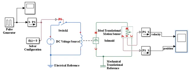
OBSERVATION:
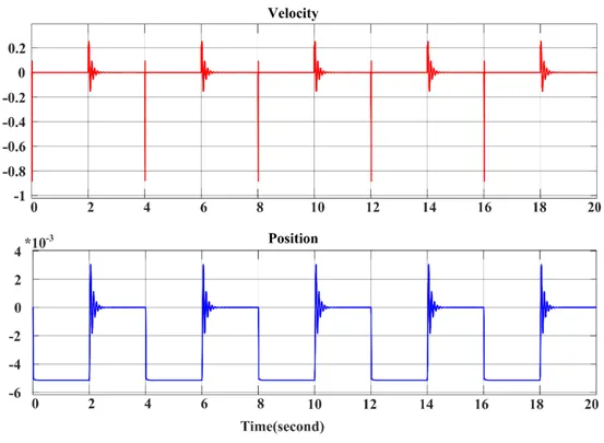
The following points are noted as we observed the Simulink model:
- 0 to 2 Second: During 0 to 2 second when the switch is OFF, we observe that the position of plunger is away from the bell and doorbell didn’t ring. In this period the velocity of plunger movement is zero.
- 2 to 4 Second: During 2 to 4 second when switch is ON, we observe movement of plunger and hence rings the doorbell.
The above two sequences are repeating for every two seconds as per the objective of the simulation.
CONCLUSION:
The doorbell system is modelled and simulated in MATLAB/Simulink 2016 version. The ideal translational motion sensor senses the motion of plunger according to the switching done to fulfill the objectives and the results are display accordingly.
N.B: The movement of plunger is observed negative in the simulation results, since the movement of ions is from C to R port of solenoid.
2.OBJECTIVE: To sense the temperature of a heater and turn ON or turn OFF the fan using thermistor in MATLAB/Simulink 2016 version with the following conditions.
For Temperature source: 20° C from 0 to 10 seconds, 27° C from 10 to 30 seconds, 23° C from 30 to 50 seconds.
For Fan: ON if the temperature is above 25° C, OFF otherwise.
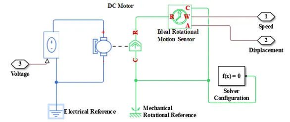
INTRODUCTION: The simulation is done to observe the behavior of thermistor while sensing the temperature of heater and turning ON and OFF of fan connected via a switch. The turning ON and OFF of fan is decided by the temperature of heater. The fan will be turn ON for temperature above 25° C and OFF otherwise. The temperature condition is generated using a repeating sequence stair block which is further connected with ideal temperature source. The output of ideal temperature source is given thermistor. Battery system is used to supply power to the thermistor and an ideal voltage sensor, and a resistor is connected in parallel with thermistor. The voltage across thermistor is measured using this ideal voltage sensor. Then the sensed voltage is given as input to fan. The temperature sensor and fan are connected via a switch, which will ON and OFF according to the condition given. DC motor is used as fan in this simulation. An ideal rotational motion sensor is used to measure the speed of fan.
Thermistor: A thermistor is a resistance thermometer, or a resistor whose resistance is dependent on temperature. The term is a combination of “thermal” and “resistor”. It is made of metallic oxides, pressed into a bead, disk, or cylindrical shape and then encapsulated with an impermeable material such as epoxy or glass. Typically, a thermistor achieves high precision within a limited temperature range of about 50ºC around the target temperature. This range is dependent on the base resistance.
There are two types of thermistors:
- Negative Temperature Coefficient (NTC) Thermistor
- Positive Temperature Coefficient (PTC) Thermistor
NTC Thermistor: In an NTC thermistor, when the temperature increases, resistance decreases. And when temperature decreases, resistance increases. Hence in an NTC thermistor temperature and resistance are inversely proportional. These are the most common type of thermistor.
The relationship between resistance and temperature in an NTC thermistor is governed by the following expression:
(1)
Where: RT is the resistance at temperature T (K)
R0 is the resistance at temperature T0 (K)
T0 is the reference temperature (normally 25°C)
β is a constant, its value is dependent on the characteristics of the material. The nominal value is taken as 4000. If the value of β is high, then the resistor–temperature relationship will be very good. A higher value of β means a higher variation in resistance for the same rise in temperature – hence you have increased the sensitivity (and hence accuracy) of the thermistor.
PTC Thermistor: A PTC thermistor has the reverse relationship between temperature and resistance. When temperature increases, the resistance increases. And when temperature decreases, resistance decreases. Hence in a PTC thermistor temperature and resistance are inversely proportional. Although PTC thermistors are not as common as NTC thermistors, they are frequently used as a form of circuit protection. Similar to the function of fuses, PTC thermistors can act as current-limiting device. When current passes through a device it will cause a small amount of resistive heating. If the current is large enough to generate more heat than the device can lose to its surroundings then the device heats up. In a PTC thermistor, this heating up will also cause its resistance will increase. This creates a self-reinforcing effect that drives the resistance upwards, therefore limiting the current. In this way, it acts as a current limiting device – protecting the circuit.
Voltage sensors: A voltage sensor is a sensor is used to calculate and monitor the amount of voltage in an object. Voltage sensors can determine both the AC voltage or DC voltage level. The input of this sensor can be the voltage whereas the output is the switches, analog voltage signal, a current signal, an audible signal, etc. Sensors are basically a device which can sense or identify and react to certain types of electrical or some optical signals. Implementation of voltage sensor and current sensor techniques have become an excellent choice to the conventional current and voltage measurement methods.
Types of Voltage Sensors:
These sensors are classified into two types like a resistive type sensor and capacitive type sensor.
Resistive Type Sensor: This sensor mainly includes two circuits like a voltage divider & bridge circuit. The resistor in the circuit works as a sensing element. The voltage can be separated into two resistors like a reference voltage & variable resistor to make a circuit of the voltage divider. A voltage supply is applied to this circuit. The output voltage can be decided by the resistance used in the circuit. So, the voltage change can be amplified. The bridge circuit can be designed with four resistors. One of these resistors can be subjected to the voltage detector device. The change in voltage can be directly exhibited. This difference alone can be amplified but the difference within the voltage divider circuit not only amplified.
Capacitor Type Sensor: This type of sensor consists of an insulator and two conductors within the center. As the capacitor is power-driven with 5 Volt, then the flow of current will be there in the capacitor. This can create revulsion of electrons within the capacitor. The difference in capacitance indicates the voltage and the capacitor can be connected within the series.
DC Motor: The DC motor is a machine that transforms electric energy into mechanical energy in form of rotation. Its movement is produced by the physical behavior of electromagnetism. DC motors have inductors inside, which produce the magnetic field used to generate movement. When a current-carrying conductor is placed in a magnetic field, it experiences a torque and has a tendency to move. In other words, when a magnetic field and an electric field interact, a mechanical force is produced. The DC motor or direct current motor works on that principle. This is known as motoring action.
SIMULINK MODEL:
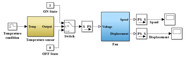
Temperature Sensor:
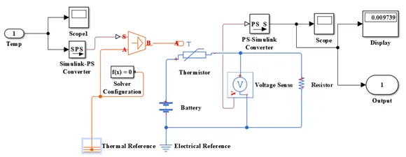
Fan:
OBSERVATION:
The following points are observed from the results:
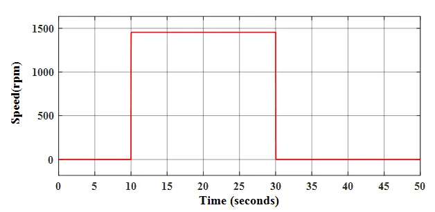
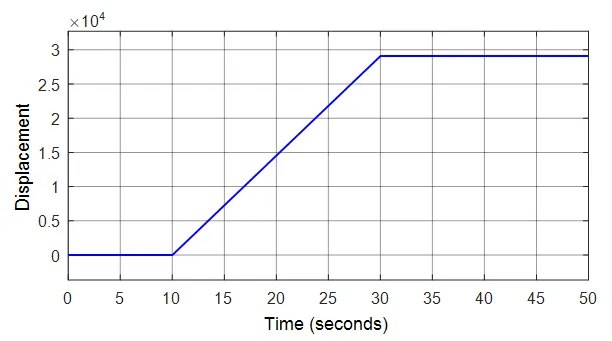
- 0 to 10 seconds: During this time, the temperature is 293 K (20° C) and we observe the Fan is in OFF state following our objective.
- 10 to 30 seconds: During this time, the temperature is 300 K (27° C) and we observe the Fan is in ON state following our objective. And the fan is rotating with the speed of 1450 rpm.
- 30 to 50 seconds: During this time, the temperature is 296 K (23° C) and we observe the Fan is in OFF state.
CONCLUSION:
The temperature of a heater is sensed using thermistor and fan is turn ON and OFF according to the mentioned objective in MATLAB/Simulink 2016 version.