Week-7 Challenge: DC Motor Control
AIM:
- Run MATLAB demo ‘Speed control of a DC motor using BJT H-bridge’. Modify the model such that the armature current doesn’t shoot up when the motor changes direction from forward to reverse.
- Refer to the help section of ‘The Four-Quadrant Chopper DC Drive (DC7) block’. Compare it with the H-bridge model.
- Make a suitable EV model using the DC7 block and make a result report.
- Explain briefly, the operation of the BLDC motor.
QUESTION-1:
- RUN MATLAB DEMO 'SPEED CONTROL OF A DC MOTOR USING BJT H-BRIDGE'.
- MODIFY THE MODEL IN A WAY THAT ARMATURE CURRENT DOESN'T SHOOT UP (WHEN THE MOTOR CHANGES DIRECTION FROM 'FORWARD TO REVERSE'.)
ANSWER-1:
- WHAT IS H-BRIDGE?:
- H-BRIDGE:
- An H-bridge is a simple circuit that lets you control a DC motor to go backward or forward.
- H-BRIDGE CONCEPT:
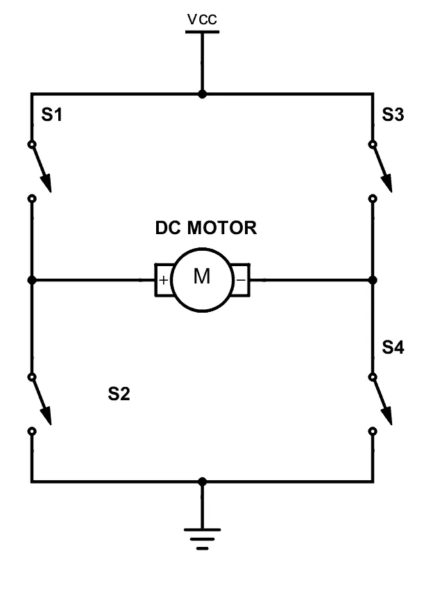
- A DC motor spins either backward or forward, depending on how you connect the polarities of the plus and the minus.
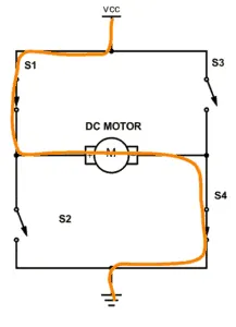
- By closing the switch 1 and 4, it connected to plus in the left side of the motor and minus to the other side of the motor. Now the motor will start spinning in one direction.
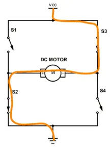
- Now, by closing the switch 2 and 3 instead it connected to plus on the right side of the motor and minus to the left side of the motor. The motor will spin in the opposite direction.
- THE H-BRIDGE CIRCUIT:
- The H-bridge circuit uses four TRANSISTORS.
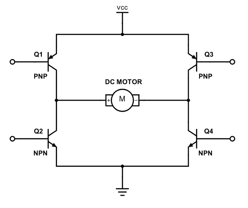
- The Transistor is a switch that can open and close with the voltage on the base. The Transistor consists of 3 pins Collector, Emitter, Base.
- Since the transistor can be a switch, it can be able to make the motor spin in either direction by turning on and off the four transistors in the circuit.
- WHAT TYPE OF TRANSISTOR TO USE?:
- The transistor that can handle enough current.
- The transistor has a low voltage drop between collector and emitter terminals.
- PROTECTION DIODES:
- A side-effect of how a motor works are that the motor will also generate electrical energy. When the transistor is disabled from the circuit to stop running the motor, it releases the energy which is BACK EMF.
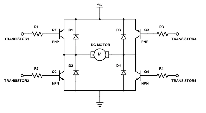
- To overcome this BACK EMF energy, Now by adding the diode in the reverse direction for the transistors, it makes a path for the current to release this energy.
- Without the Protection Diode, There is a risk that the voltage rises and damages the Transistors.
- H-BRIDGE:
- RUN MATLAB DEMO 'SPEED CONTROL OF A DC MOTOR USING BJT H-BRIDGE'.
- Simulink model for "SPEED CONTROL OF A DC MOTOR USING BJT H-BRIDGE":
- This model consists of,
- DC motor.
- Four IGBT Transistors.
- Pulse Generator for Switching ON and OFF.
- This model produces the output results of,
- IGBT current
- Diode current
- Speed of the motor.
- Armature Current
- Load Torque.
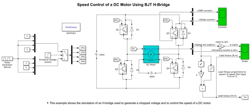
- In this model, we control the dc motor using BJT Transistor which is IGBT.
- TRIGGERING LOGIC OF CONTROL:
- Trigger Logic Control of all the four transistors Gate signals of Q1, Q2, Q3, Q4.
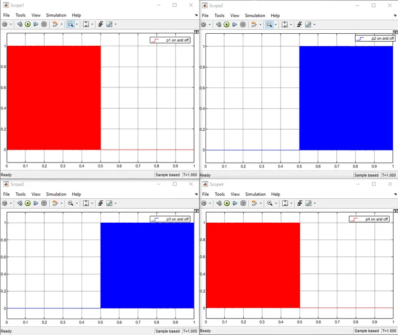
- Here, the Triggering switching for the transistor is created by Pulse Generator.
- Pulse Generator creates a Frequency of ON and OFF Square Waves and Connected to Armature voltage control for all the Gate frequency of p1, p2, p3, and p4.
- ON and OFF values are 0 to 1.
- P1 Triggering starts from ON from 0 to 0.5 up to 1 and OFF from 0.5 to 1 up to 1.
- P2 Triggering starts from ON from 0.5 to 1 up to 1 and OFF from 0 to 0.5 up to 1.
- P3 Triggering starts from ON from 0.5 to 1 up to 1 and OFF from 0 to 0.5 up to 1.
- P4 Triggering starts from ON from 0 to 0.5 up to 1 and OFF from 0.5 to 1 up to 1.
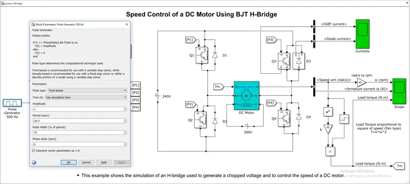
- In this model, The pulse generator uses 75% of the Duty cycle in the Triggering signal.
- The pulse generator is connected to Armature Voltage control for switching the Transistors ON and OFF.
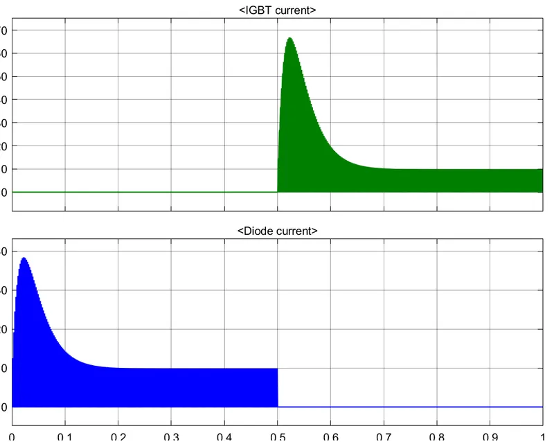
- The IGBT peak current is higher than the Diode current value.
- Both IGBT current and Diode current comes to rest for the same value which is 10 amps.
- Diode current starts from 0 to 0.5 time period, and it comes to OFF from 0.5 to 1 time period.
- IGBT current is OFF from 0 to 0.5 time period, and it starts from 0 to 0.5 time period.
- OUTPUT SPEED:
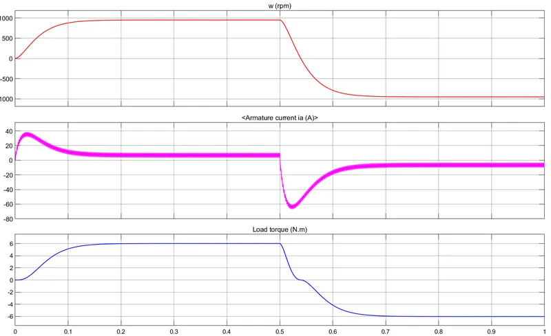
- The motor runs gradually increases from 0 to 1000 RPM and the motor runs in a constant speed of 1000 rpm up to 0.5 time period and gradually decreases from 1000 to -1000 rpm and the motor becomes constant at -1000 RPM
- ARMATURE CURRENT:
- The starting Current of Armature attends the peak value of 38 amps and becomes 10 amps up to the ON-time period.
- At the OFF-time period The Armature currents the Negative Peak value of -65 amps and becomes -10 amps.
- LOAD TORQUE:
- At the ON-time period, the Load torque gradually increases from 0 to 6 Newton meters and produces a constant 6 newton-meters up to 0.5.
- At the OFF-time period, The load torque gradually decreases from 6 to -6 Newton meters and produces a Negative torque of constant -6 newton meters up to 1.
- OUTPUT SPEED:
- This model consists of,
- Simulink model for "SPEED CONTROL OF A DC MOTOR USING BJT H-BRIDGE":
- MODIFY THE MODEL IN A WAY THAT ARMATURE CURRENT DOESN'T SHOOT UP (WHEN THE MOTOR CHANGES DIRECTION FROM 'FORWARD TO REVERSE'.)
- HOW TO REDUCE THE ARMATURE CURRENT, WHEN THE MOTOR CHANGES DIRECTION FROM FORWARD TO REVERSE.
-
- TO REDUCE THE ARMATURE CURRENT, WHEN THE MOTOR CHANGES DIRECTION FROM FORWARD TO REVERSE
- IT IS POSSIBLE THAT WHEN THE DUTY CYCLE VALUE IS DECREASED THE ARMATURE CURRENT DECREASES.
- TO REDUCE THE ARMATURE CURRENT, WHEN THE MOTOR CHANGES DIRECTION FROM FORWARD TO REVERSE
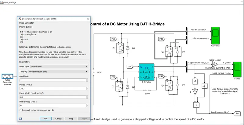
- In this model, The pulse generator uses 65% of the Duty cycle in the Triggering signal.
- The pulse generator is connected to Armature Voltage control for switching the Transistors ON and OFF.
- Now the duty cycle is decreased to 65% from 75%, the Armature current also decreases.
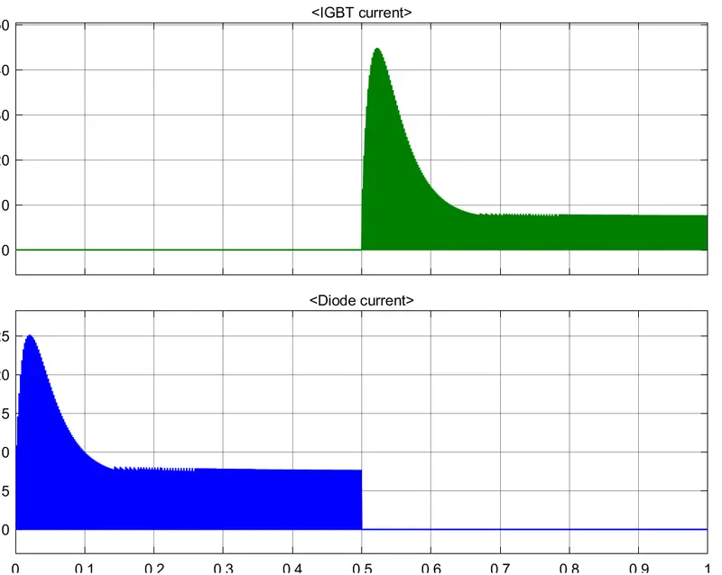
- The IGBT peak current is higher than the Diode current value.
- Both IGBT current and Diode current comes to rest for the same value which is 8 amps.
- Diode current starts from 0 to 0.5 time period, and it comes to OFF from 0.5 to 1 time period.
- IGBT current is OFF from 0 to 0.5 time period, and it starts from 0 to 0.5 time period.
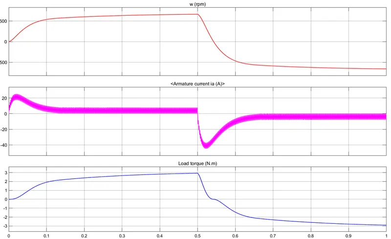
- OUTPUT SPEED:
- The motor runs gradually increases from 0 to 600 RPM and the motor runs in a constant speed of 600 rpm up to 0.5 time period and gradually decreases from 600 to -600 rpm and the motor becomes constant at -600 RPM
- ARMATURE CURRENT:
- The starting Current of Armature attends the peak value of 23 amps and becomes 10 amps up to the ON-time period.
- At the OFF-time period The Armature currents the Negative Peak value of -44 amps and becomes -10 amps.
- LOAD TORQUE:
- At the ON-time period, the Load torque gradually increases from 0 to 3 Newton meters and produces a constant 3 newton-meters up to 0.5.
- At the OFF-time period, The load torque gradually decreases from 3 to -3 Newton meters and produces a Negative torque of constant -3 newton meters up to 1.
- OUTPUT SPEED:
- HOW TO REDUCE THE ARMATURE CURRENT, WHEN THE MOTOR CHANGES DIRECTION FROM FORWARD TO REVERSE.
- RESULT:
- THE ARMATURE CURRENT CAN BE REDUCED WHEN THE DUTY CYCLE VALUE REDUCED.
QUESTION-2:
- WHAT IS FOUR-QUADRANT CHOPPER DC DRIVE (DC7) BLOCK.
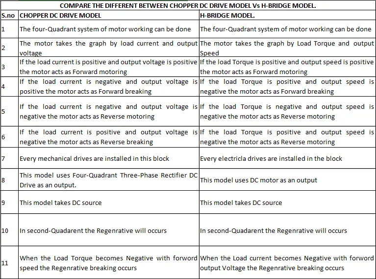
- COMPARE THE DIFFERENT BETWEEN CHOPPER DC DRIVE MODEL Vs H-BRIDGE MODEL.
ANSWER-2:
- WHAT IS FOUR-QUADRANT CHOPPER DC DRIVE (DC7) BLOCK.
- The Four-Quadrant Chopper DC Drive (DC7) block represents a four-quadrant DC-supplied chopper drive (or DC-DC PWM converter) for DC motors.
- This drive features closed-loop speed control with a four-quadrant operation.
- The speed control loop outputs the reference armature current of the machine.
- Using a PI current controller the chopper duty cycle corresponding to the commanded armature current is derived.
- This duty cycle is then compared with a sawtooth carrier signal to obtain the required PWM signals for the chopper.
-
- The main Advantage of this DRIVE is that it can operate in all four quadrants
- Forward motoring
- Reverse regeneration
- Reverse motoring
- Forward regeneration
- Due to the use of high switching frequency DC-DC converters, a lower armature current ripple is obtained.
- The main Advantage of this DRIVE is that it can operate in all four quadrants
- THE LIMITATION OF THIS DRIVE:
- This drive need's four switching devices are required, which increases the complexity of the drive system.
- The Four-Quadrant Three-Phase Rectifier DC Drive block uses these blocks from the Electric Drives/Fundamental Drive Blocks library:
- Speed Controller (DC)
- Regulation Switch
- Current Controller (DC)
- Bridge Firing Unit (DC)
- COMPARE THE DIFFERENT BETWEEN CHOPPER DC DRIVE MODEL Vs H-BRIDGE MODEL.
QUESTION-3:
- MAKE A SUITABLE EV MODEL USING THE DC7 BLOCK AND MAKE A RESULT REPORT.
ANSWER-3:
- The Simulink model of Electric Vehicle using DC7 block:
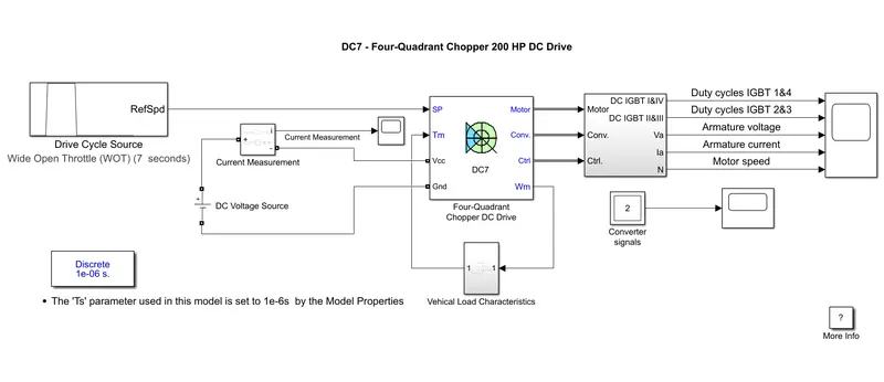
- This model consists of,
- Drive cycle source which connected to SP
- DC voltage source POsitive to Vcc and Negative to Gnd( ground)
- Vehicle Load Characteristics where we get Load torque and Speed of the Vehicle.
- The Four-Quadrant chopper DC drive consists of,
- Motor Tab
- Control Tab
- Conventional Tab
- This model consists of,
- Vehicle Load Characteristics where we get Load torque and Speed of the Vehicle:
- By the Torque equation value of the Load-Torque can be calculated by the speed of the motor in radian per second.
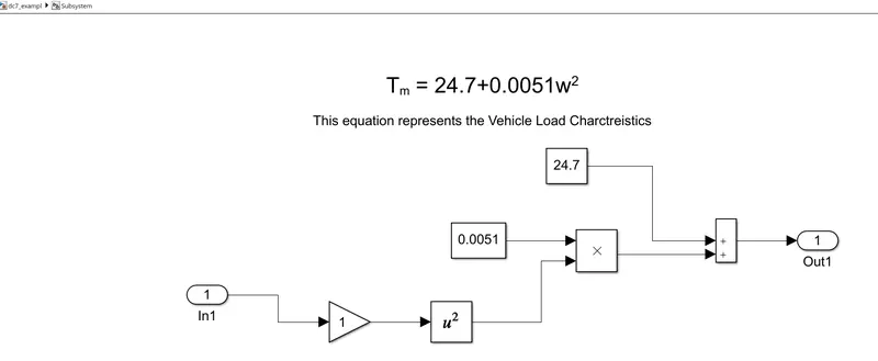
- The port in 1 is connected to the motor speed
- The port out 1 is connected to the load torque.
- By, which it deals with the vehicle characteristics of `T_m=24.7+0.0051omega^2`.
- By the Torque equation value of the Load-Torque can be calculated by the speed of the motor in radian per second.
- Drive Cycle Source:
- The Wide Open Throttle Drive cycle source is used
- DUTY CYCLE IGBT OF 1 AND 4:
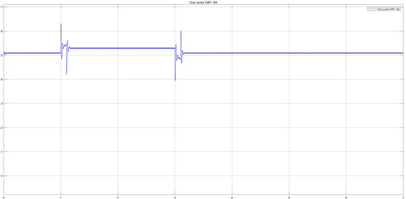
- The Duty cycle of IGBT 1 & 4 creates Positive triggering.
- The Duty cycle of IGBT 1 & 4 is zero up to 1 and increases to 0.6 and immediately comes to zero.
- The Duty cycle of IGBT 1 & 4 is zero up to 3 and decreases to 0.4 and immediately comes to zero.
- DUTY CYCLE IGBT OF 2 AND 3:
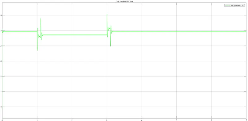
- The Duty cycle of IGBT 2 & 3 creates Negative triggering.
- The Duty cycle of IGBT 2 & 3 is zero up to 1 and increases to 0.4 and immediately comes to zero.
- The Duty cycle of IGBT 2 & 3 is zero up to 3 and decreases to 0.6 and immediately comes to zero.
- A RESULT REPORT OF EV MODEL WITH DC7 BLOCK:
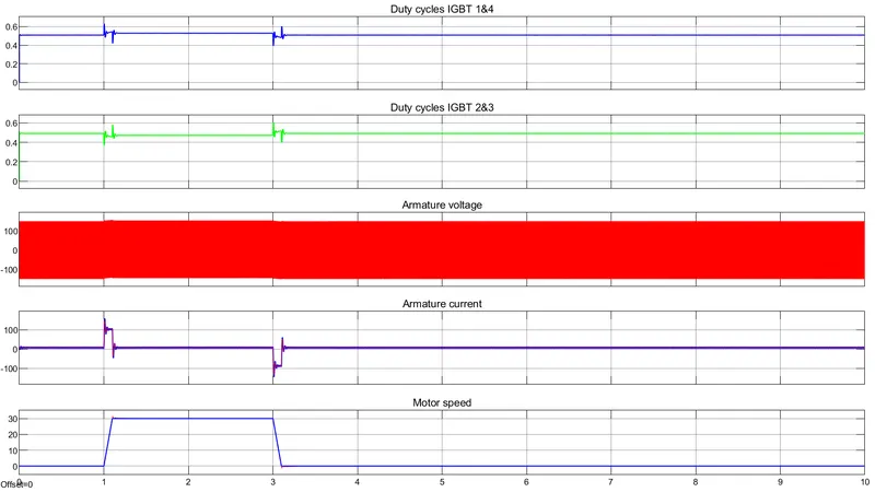
- ARMATURE VOLTAGE:
- The armature voltage is constant of 150 volts to -150 volts throughout the cycle.
- At the triggering point, the armature voltage becomes high.
- ARMATURE CURRENT:
- The armature current is zero up to 1 and increases to 150 amps and immediately comes to zero.
- The armature current is zero up to 3 and decreases to -150 amps and immediately comes to zero.
- MOTOR SPEED:
- The Motor Speed is zero up to 1 and increases to 30 rpm and runs in constant of 30 rpm up to 3 and decreases to zero which is an OFF-time period.
- ARMATURE VOLTAGE:
QUESTION-4:
- EXPLAIN BRIEFLY, THE OPERATION OF THE BLDC MOTOR.
ANSWER-4:
-
What is a BLDC Motor?
- A Brushless DC Motor is similar to a Brushed DC Motor but as the name suggests, a BLDC doesn’t use brushes for commutation but rather they are electronically commutated.
- In conventional Brushed DC Motors, the brushes are used to transmit the power to the rotor as they turn in a fixed magnetic field.
- A BLDC motor used electronic commutation and thus eliminates the mechanically torn brushes.
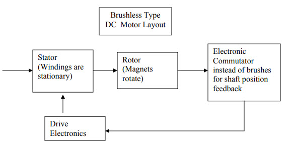
- LAYOUT OF BLDC MOTOR:
- LAYOUT OF BLDC MOTOR:
-
Construction of BLDC Motor:
- The main design difference between brushed and brushless motors is the replacement of a mechanical commutator with an electric switch circuit.
- a BLDC Motor is a type of synchronous motor in the sense that the magnetic field generated by the stator and the rotor revolve at the same frequency.
- The Brushless Motor is available in Three Configurations,
- Single-phase.
- Two-phase.
- Three-phase.
- The Three-phase BLDC Motor is the most common one we use in Electric vehicle applications.
- The Cross-Section View of a BLDC Motor:
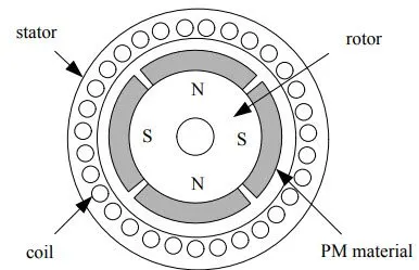
- The BLDC Motor consists of,
- STATOR.
- ROTOR.
- COIL.
- PM MATERIAL.
- A BLDC motor consists of two main parts Stator and Rotor.
- Stator:
- The structure of the stator of a BLDC motor is similar to that of an induction motor.
- The Stator is made up of stacked steel laminations with axially cut slots for winding.
- The winding in Stator BLDC is slightly different than that of the traditional induction motor.
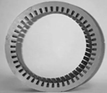
- Generally, most of the BLDC motors consist of three stator windings that are connected in star or ‘Y’ fashion (without a neutral point).
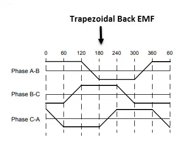
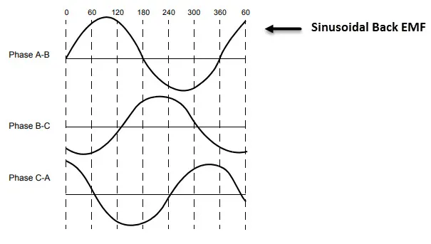
- The stator windings are further divided into Trapezoidal and Sinusoidal Motors.
- Trapezoidal Motor:
- In a Trapezoidal motor, both the drive current and the back emf are in a shape of a Trapezoid.
- Sinusoidal Motor:
- In a Sinusoidal Motor, both the drive current and the back emf are in a shape of a sinusoidal.
- Trapezoidal Motor:
- Rotor:
- The rotor part of the BLDC Motor is made up of permanent magnets.
- The permanent magnets use rare earth alloy magnets like,
- Neodymium (Nd).
- Samarium Cobalt (SmCo).
- Alloy of Neodymium Ferrite Boron (NdFeB).
- Based on the application, the number of poles can vary between two and eight with North (N) and South (S) poles placed alternately.
- The outer periphery of the rotor:
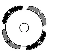
- The magnets are placed on the outer periphery of the rotor.
- The magnetic-embedded rotor:
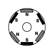
- Where rectangular permanent magnets are embedded into the core of the rotor.
- The iron core of the rotor:
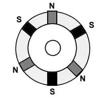
- The magnets are inserted into the iron core of the rotor.
- The outer periphery of the rotor:
- Position Sensors (HALL Sensors):
- Now the BLDC motor has no Brushes, the commutation is controlled electrically.
- In order to rotate the motor, the windings of the stator must be energized in a sequence, and the position of the rotor which the North poles and South poles of the rotor must be known to precisely energize a particular set of stator windings.
- A Position Sensor, which is usually a Hall Sensor is generally used to detect the position of the rotor and transform it into an electrical signal.
- HALL-EFFECT SENSOR:
- A Hall-effect sensor (or simply Hall sensor) is a device to measure the magnitude of a magnetic field. Its output voltage is directly proportional to the Magnetic field strength through it.
- The Hall-sensor is used for,
- Proximity Sensing.
- Positioning Sensor.
- Speed Detection.
- Current Sensing.
- Most BLDC Motors use three Hall Sensors that are embedded into the stator to sense the rotor’s position.
- The output of the Hall Sensor will be either HIGH or LOW.
- Depending on whether the North or South pole of the rotor passes near it
- The output of the Hall Sensor will be either HIGH or LOW.
- By combining the results from the three sensors, the exact sequence of energizing can be determined.
- Stator:
- The BLDC Motor consists of,
- THE WORKING PRINCIPLE OF BLDC MOTOR:
- Consider the following setup of three windings in the stator designated A, B, and C. For the sake of understanding, let us replace the rotor with a single magnet.
-
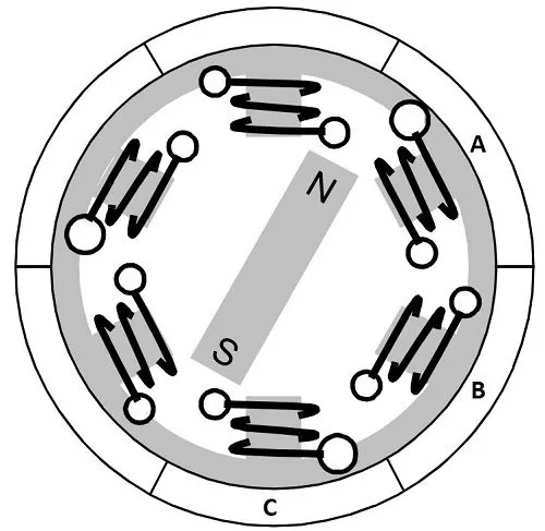
- We know that when a current is applied through a coil, a magnetic field is generated and the orientation of the field lines i.e. the poles of the generated magnet will depend on the direction of the current flowing through the coil.
- Now by supply current to coil A so that it will generate a magnetic field and attract the rotor magnet. The position of the rotor magnet will shift slightly clockwise and will align with coil A. similarly for coil B and coil C the magnet rotates in the clockwise direction
-
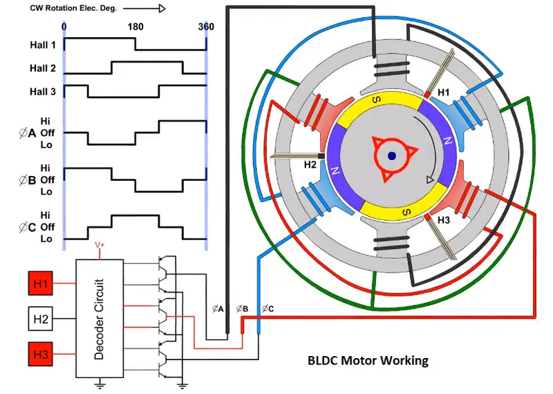
- Here, the Three-phase BLDC motor is used and the phases are A, B, &C.
- These phases are connected to an Electronically commutator which is a power electronic controller which acts as an Inverter.
- The Hall sensor is placed between poles to sense the position of the rotor.
- Here we have taken three Hall sensors and placed them in Stator.
- Each phase signal is combined with High, Low, and OFF.
- The hall signal is taken as the frequency of 0 to 360 degrees.
- When The Hall-1 is OFF to ON, Hall-2 is OFF, and Hall-3 is OFF to ON. So Hall-1 and Hall-3 are present.
- Then phase A is in the OFF signal, phase B is OFF to High, and phase C is Low.
- Similarly, in three phases if one phase is of the other two phases are acts as positive and negative.
- Advantages of Brushless DC motor:
- Less overall maintenance due to absence of brushes
- Less electromagnetic interference
- Low noise due to absence of brushes
- Higher speed range and lower electric noise generation.
- Higher dynamic response due to low inertia and carrying windings in the stator
- Long-life as no inspection and maintenance is required for commutator system
- Limitations of Brushless DC motor:
- These motors are costly
- The electronic controller required to control this motor is expensive
- The need for additional sensors
- Requires complex drive circuitry
- Applications of Brushless DC motor:
- Electric vehicles, hybrid vehicles, and electric bicycles can be constructed
- Industrial robots, CNC machine tools, and simple belt-driven systems
- Fans, pumps, and blowers with low noise.