Week -2
AIM:
- CONSTRUCT THE SIMULINK MODEL FOR DOORBELL USING SOLENOID.
- CONSTRUCT THE SIMULINK MODEL FOR SENSING THE TEMPERATURE OF A HEATER AND TURN ON OR TURN OFF THE FAN USING THERMISTOR
TOPIC-1:
To construct the Simulink model for doorbell using a solenoid. Our objective is first what is a solenoid and how it helps in the doorbell.
REAL MODEL CONSTRUCTION:
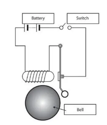
SOLENOID:
A solenoid is a type of electromagnet, the purpose of which is to generate a controlled magnetic field through a coil wound into a tightly packed helix. The coil can be arranged to produce a uniform magnetic field in a volume of space.
The solenoid is also called a HELICAL COIL.
SOLENOID BLOCK:
The solenoid block is used in Simulink to create the block diagram of a user model. In this construction of the model system solenoid acts as a working principle of a doorbell.
DOORBELL AND SWITCHING CONDITIONS:
- when the switch is closed the electromagnet receives electrical power from the battery and pulls the metal arm to hit the bell producing sound.
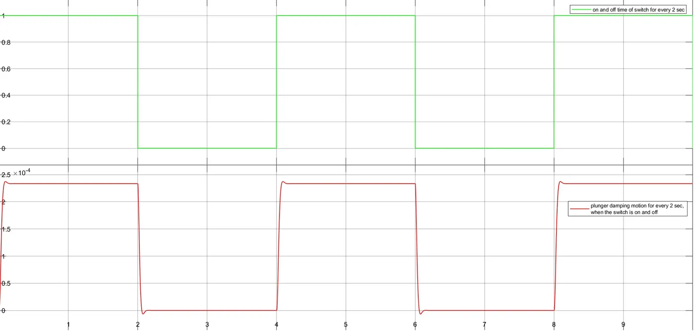
- Create a situation where the switch is closed for 2 seconds and then released for DoorBell.
- Observe the physical movement of the plunger for the make plot whether the switch is on or off.
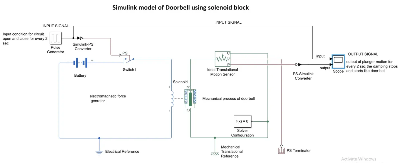
CONSTRUCT THE SIMULINK MODEL FOR DOORBELL USING SOLENOID.
- Solenoidblock is located at the Simulink library browser from - Simscape / Electrical / Electromechanical / Mechatronic Actuators.
- Here solenoid acts as a doorbell, where the electromagnet receives electrical power from the battery and pulls the metal arm to hit the bell producing sound. The metal arm is nothing but a plunger in the Solenoid block.
- Solenoid block is consists of an electrical system and a mechanical system.
- In the electrical system, we generate source voltage, so that it produces electromotive force EMF to the coil to magnetize.
- In a mechanical system, the plunger is attracted and repulsion to electromotive force from the electric system.
- By applying the switch block at the electrical system, we give switching conditions
- we take switching conditions from the pulse generator block, where we create the condition for the switch to run every 2 seconds the switch is open and close.
- Then at mechanical system output is taken from the scope plot to display at which time the plunger damping is moving for every 2 seconds
SIMULINK BLOCK DIAGRAM:
INPUT AND OUTPUT PLOT:
TOPIC-2:
To construct a simulation model for sensing the temperature of heat and turn on and off the fan using thermistor.
CONDITIONS FOR TEMPERATURE SOURCE AND FAN CONDITIONS:
- Temperture source are T1,T2,T3.
- T1 from 200c from 0 to 10 seconds of a time period.
- T2 from 270c from 10 to 30 seconds of a time period.
- T3 from 230c from 30 to 50 seconds of a time period.
- Fan condition
- when the temperature source is below 250c fan is in OFF condition.
- when the temperature source is above 250c fan is in On condition.
BLOCKS TO KNOW:
- THERMISTOR:
A thermistor is a resistance thermometer or a resistor whose resistance is dependent on temperature. The term is a combination of “thermal” and “resistor”. It is made of metallic oxides, pressed into a bead, disk, or cylindrical shape and then encapsulated with an impermeable material such as epoxy or glass.
- TEMPERATURE SOURCE:
A temperature source is a constant source of thermal energy.
- TEMPERATURE SENSOR:
A temperature sensor is used to sense how much thermal energy is coming out of a single point.
- DC MOTOR:
A DC motor is any of a class of rotary electrical motor that converts direct current electrical energy into mechanical energy. It can acts as a FAN is our simulation
- IDEAL ROTATIONAL MOTION SENSOR:
The Ideal Rotational Motion Sensor block represents an ideal mechanical rotational motion sensor.
- CONTROLLED VOLTAGE SOURCE:
The Controlled Voltage Source block represents an ideal voltage source that is powerful enough to maintain the specified voltage at its output regardless of the current flowing through the source, Where v = vs.
- VOLTAGE SENSOR:
The Voltage Sensor block represents an ideal voltage sensor, that is, a device that converts voltage measured between two points of an electrical circuit into a physical signal proportional to the voltage.
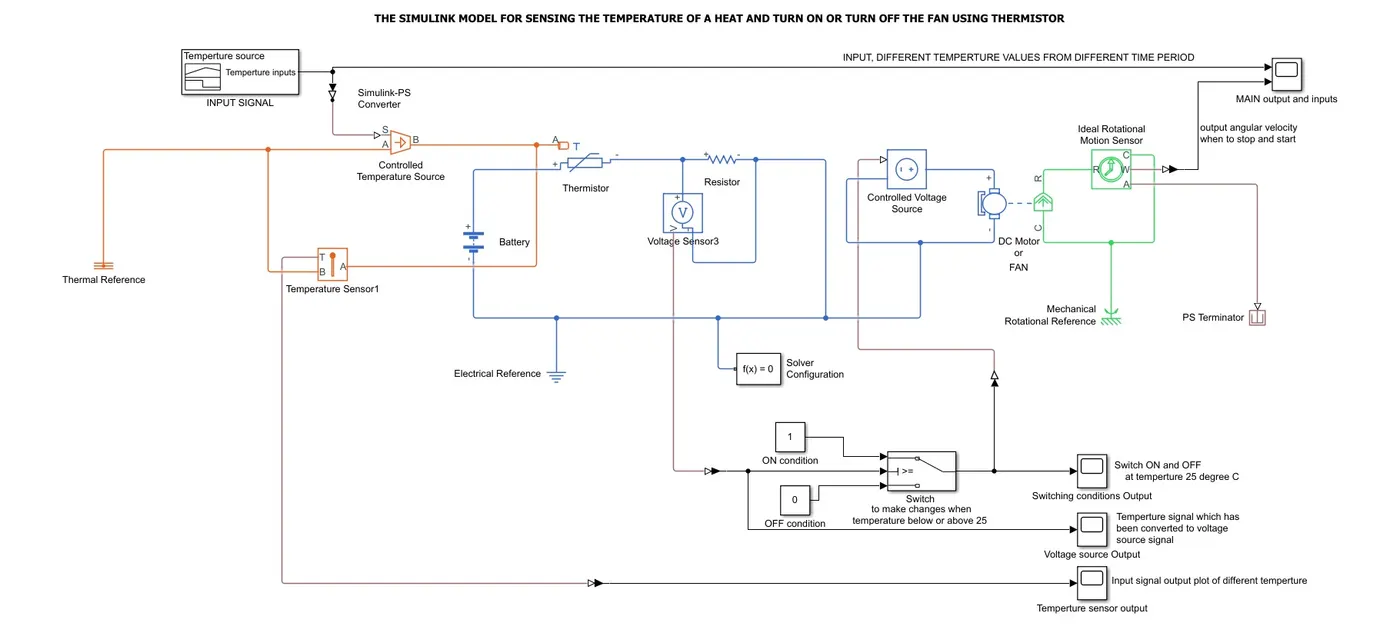
CONSTRUCT THE SIMULINK MODEL FOR SENSING THE TEMPERATURE OF A HEAT AND TURN ON OR TURN OFF THE FAN USING THERMISTOR:
In this simulation, we use three systems, a thermal system, an electrical system, a mechanical system. By these system blocks, we create a simulation model for sensing the temperature of heat and turn on and off the fan using a thermistor.
STEPS:
- Let's create the Temperature source conditions using the signal builder block. Where we give all the temperature T1, T2, T3.
- T1 from 200c from 0 to 10 seconds of a time period, T2 from 270c from 10 to 30 seconds of a time period, T3 from 230c from 30 to 50 seconds of a time period.
- Now signal builder is connected to a controlled temperature block, where it sends the input signal of each temperature value to the THERMISTOR BLOCK. Up to this process is the Thermal system.
- Now from the Electrical system, the value of the thermistor is taken.
- The Electrical circuit is constructed to the DC MOTOR or FAN to get the output fan conditions to when the fan should on-off from varying the value from the voltage sensor to a controlled voltage source to the DC motor system.
- Controlled voltage source input is taken from a conditional switch output. The input is a condition that when the Temperature source is below 250c FAN or DC MOTOR is in OFF condition or when the temperature source is above 250c FAN or DC MOTOR is in On condition.
- MAin input values for the switch is the value of voltage output sensor value.
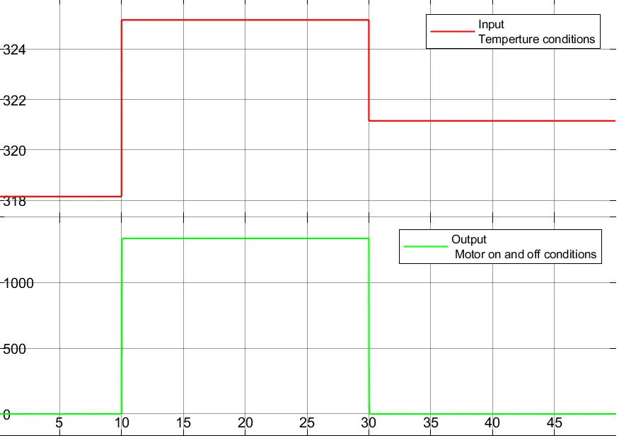
- In a mechanical system, we take the output from IDEAL ROTATIONAL MOTION SENSOR at which when the motor stop and run condition, with running RPM and stopping RPM.
- For every system, we need to put a reference point which is Thermal Reference, Electrical Reference, and Mechanical Rotatory Reference blocks.
SIMULATION BLOCK DIAGRAM:
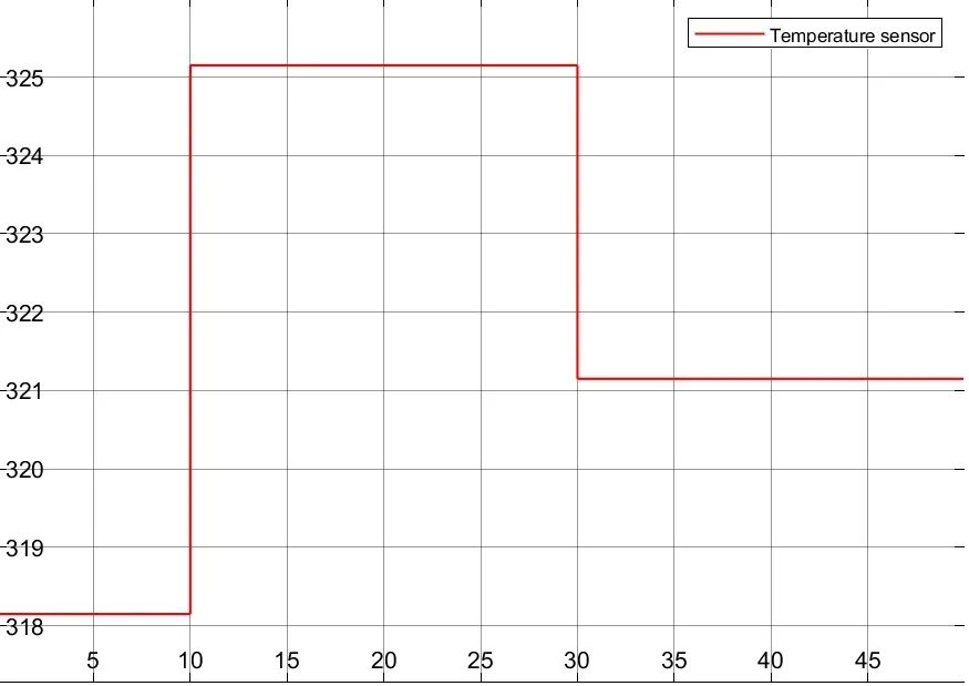
TEMPERATURE SENSOR OUTPUT PLOT:
- Temperture source are T1,T2,T3.
- T1 from 200c from 0 to 10 seconds of a time period.
- T2 from 270c from 10 to 30 seconds of a time period.
- T3 from 230c from 30 to 50 seconds of a time period.
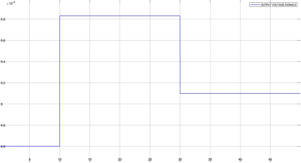
VOLTAGE SOURCE OUTPUT:
- Voltage at each Temperture source are T1, T2, T3 are V1, V2, V3
- V1 from 0.0046v from 0 to 10 seconds of a time period.
- T2 from 0.0058v from 10 to 30 seconds of a time period.
- T3 from 0.0051v from 30 to 50 seconds of a time period.
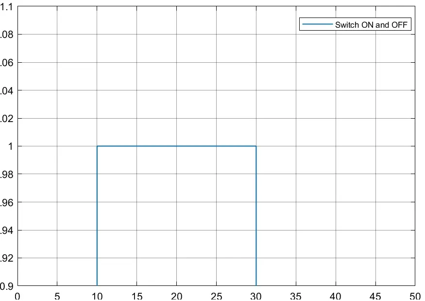
SWITCHING CONDITION PLOT:
- For temperature
- when the temperature source is below 250c fan is in OFF condition.
- when the temperature source is above 250c fan is in On condition.
- But from voltage threshold value of 0.0052v
- when the temperature source is below 0.0052v fan is in OFF condition.
- when the temperature source is above 0.0052v fan is in On condition.
MAIN INPUT AND OUTPUT RESULTS:
Input:
- The voltage at each Temperature source are T1, T2, T3 are V1, V2, V3
- V1 from 0.0046v from 0 to 10 seconds of a time period.
- T2 from 0.0058v from 10 to 30 seconds of a time period.
- T3 from 0.0051v from 30 to 50 seconds of a time period.
Output:
- a voltage threshold value of 0.0052v as a reference
- when the temperature source is below 0.0052v fan is in OFF condition.
- when the temperature source is above 0.0052v fan is in On condition.
- The motor becomes stop and run for the above conditions