DC Motor Control
Target:-
- To find out the control of dc motor using power electronic devices
- Designing a suitable EV.
- Discussion of BLDC motors.
Objective:-
- Run MATLAB demo ‘Speed control of a DC motor using BJT H-bridge’. Modify the model such that the armature current doesn’t shoot up when the motor changes direction from forward to reverse.
- Refer to the help section of ‘The Four-Quadrant Chopper DC Drive (DC7) block’. Compare it with the H-bridge model.
- Make a suitable EV model using the DC7 block and make a result report.
- Explain in a brief the operation of the BLDC motor.
Theory:-
-
Power electronics is a device which is the combination of two types of studies, i.e., High power and electronics components those are MOSFET, IGBT, BJT, Diodes, SCR, etc these devices wear only been operating in very low voltage and current in fact this is only in electronic devices. In the early days, it was very difficult to getting the conversion of power into a different form but nowadays with the invention of power electronics in the early 1920s, the requirements of these devices replaced old model electrical components which wear used earlier and making the devices compact.
The use of power electronics changes the earlier problem of heating, power loss, increases efficiency, reduced cost, environmentally friendly and can be made easily with less manpower as there are machines thises is all possible of new elements of semiconductors i.e., GaN, SiO. Here is the brief description of power Electronics components with their diagram-:
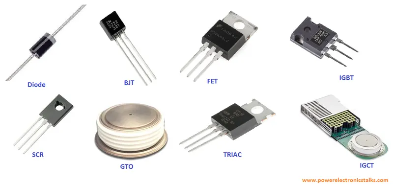
-
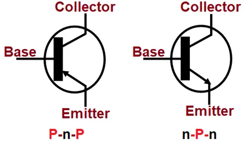
Name Description Diagram BJT BJT stands Bipolar Junction Transistor is a device having three terminals Emitter, Collector and Base. This element is rarely used it is a current device but is controlled by voltage when Base voltage is applied then the current starts to conduct from the cathode to the emitter this is a voltage sensing element and is partially ON.
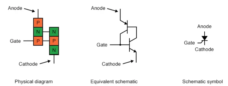
SCR SCR stands for Silicon Controlled Rectifier. SCR is a three-channel device and the names of the terminals are Gate, Anode, Cathode. these devices are used when er need to control high power, possible coupled with high voltage is demanded. The SCR works only with high voltage if there is low voltage then this will not get conducted.
In another way, if we apply a little gate voltage to the gate then it will start to flow the supply current having Annode being connected to positive and cathode being connected to negative, once the gate is open it is not n easy to apply any more gate current to the SCR. It can only be turned off if we have to cut down the supply or reverse biased it by alternating the polarity. This is a current sensing element and it is normally ON.
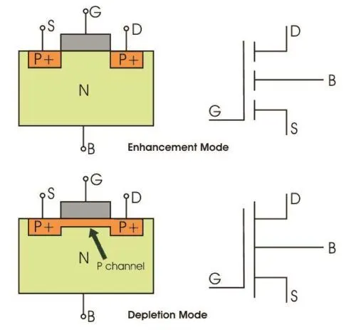
MOSFET MOSFET stands for Metal Oxide Semiconductor Field Effect Transistor it has 4 terminal but normally the 2 terminals are short circuit so, it has three terminals those are. Source, Gate, Drain. The supply is given to the source and the drain and the controlling is done by the gate terminal.
This is ON when there is some gate voltage is given then the conduction is possible In the source-drain cause this cause the short-circuited and it is necessary for having a gate voltage if due to some reason the gate voltage is 0V then there is an open circuit which results in switch OFF. This is only used in those circuited where the high speed of switching is required. These elements produce less heat as compare to its competitor and this is the voltage controlling device nit current as IGBT i.m., the MOSFET is a voltage sensing element and is normally OFF.
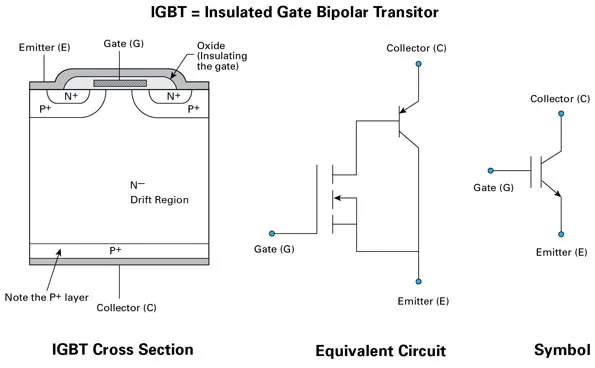
IGBT IGBT stands for Insulated Gate Bipolar Transistor. This is a Three terminal device the name if the terminal is Emitter, Gate, Collector. These devices used when we need to vary a large amount of frequency and are used in variable frequency device. In normal the devices is activated when there is a valid current applied in the Gate then the channel is formed and the current flows across the collector (+) and comes out from the emitter(-)
When the current is 0V then there is no current flows and is OFF state. These are current control devices not voltage control devices. This is normally in OFF state
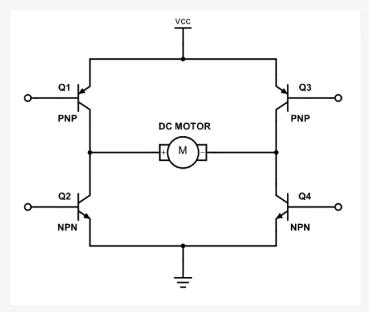
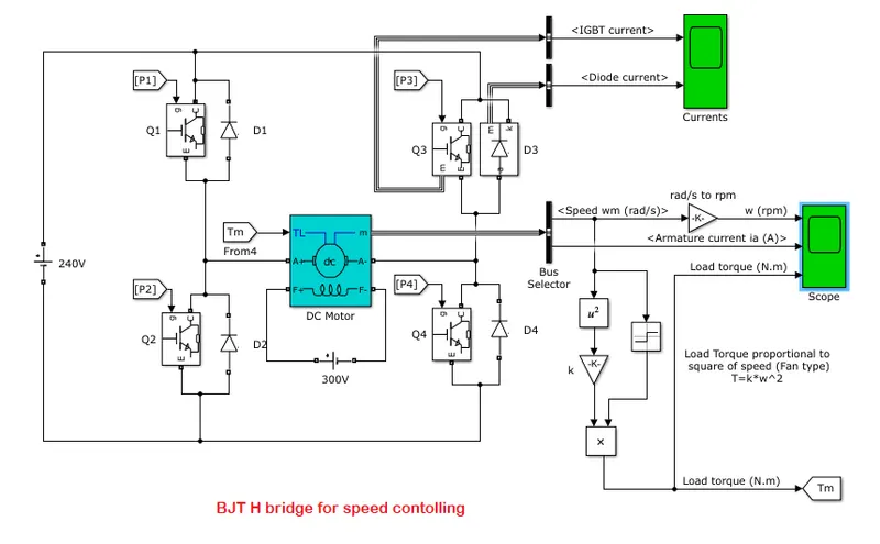
The use of power_H_Bridge is to control the speed of the dc motor by controlling the duty cycle we can control the speed this can be achieved by changing the armature current as we all know that speed is directly proportional to the armature current we are using this bridge as it very easy to control the input current by controlling the gate current by Pulse Width Modulation (PWM) method we can change the speed.
Let's see this with the only switch in place of the Power Electronic components when we connect four switches are connected. The switch S1 and S3 are kept ON then the flow of current is going like Vs > S1 > Ma > Mb > S3 > Vs this current flow shown drives the motor in the clockwise direction. Similarly, when the switch S2 and S4 are ON then the flow of current is going like Vs > S2 > Mb > Ma > S4 > Vs this current flow shown drives the motor in an anticlockwise direction.
So, now we have to do the switching at such a speed that the speed of the motor can be controlled easily. And the using of Power Electronics elements will also help in the regulation of current flowing in the armature winding in this way we can be able to control the speed of the DC Motor and this and to avoid short circuit we can also provide switching delay or we can add diodes for freewheeling which will keep the motor running and there will be no issue in controlling the speed
To overcome some issues of a sudden increase in peak current we have to modulate the switching time so that the armature current doesn't exceed the peak value.
Using the above process we have to replace the switch with a Power IGBT which will act as the switch and in addition to that we have to make a controlling circuit which will be given to the gate of the IGBT so, the additional controlling circuit is given in the circuit diagram the pulse generator will generate the required pulse that will make the motor run without exceeding the Armature Current.
-
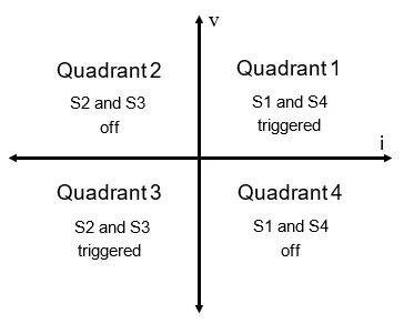
- The four-quadrant chopper means that the motor has to run in all the four-quadrant i.e., in this if we keep both the voltage and the current positive then the motor will be in motoring mode, if the voltage is positive and the current is negative then it is in a braking mode that is forward breaking. In the same way the same motor act as a motor and as well as a generator.
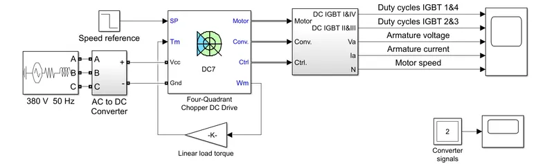
The 200 HP DC motor is separately excited with a constant 150 V DC field voltage source. The armature voltage is provided by an IGBT converter controlled by two PI regulators. The converter is fed by a 515 V DC bus obtained by rectification of a 380 V AC 50 Hz voltage source. To limit the DC bus voltage during dynamic braking mode, a braking chopper has been added between the diode rectifier and the DC7 block.
The first regulator is a speed regulator, followed by a current regulator. The speed regulator outputs the armature current reference (in p.u.) used by the current controller to obtain the electromagnetic torque needed to reach the desired speed. The speed reference change rate follows acceleration and deceleration ramps to avoid sudden reference changes that could cause armature over-current and destabilize the system. The current regulator controls the armature current by computing the appropriate duty ratios of the 5 kHz pulses of the four IGBT devices (Pulse Width Modulation). For proper system behaviour, the instantaneous pulse values of IGBT devices 1 and 4 are opposite to those of IGBT devices 2 and 3. This generates the average armature voltage needed to obtain the desired armature current. To limit the amplitude of the current oscillations, a smoothing inductance is placed in series with the armature circuit.
Comparison with the H Bridge Model :
-
H-bridge is like 4 quadrant DC choppers are also capable of braking operation, without using air resistance, friction or physical brakes to bring the motor to a halt.4 quadrant DC choppers are generally used in automotive applications while BJT H-bridge is used in robotics and electromechanical applications
-
Unlike 4 quadrant DC choppers, BJT H-bridge are not capable of regenerative braking, this makes them unsuitable for EV applications.
-
In 4 quadrant DC choppers the current signals are interrupted with each other to change the rotation of the motor, this is done with the help of a drive cycle to change the values of the current signal which in turn changes the direction of rotation of the motor. In BJT H- bridge the polarity of the current is changed to change the direction of rotation of the motor.
-
In 4 quadrant DC choppers, a PI controller is used to control the speed and the current, this is not done in BJT H-bridge.
-
Ia n four-quadrant chopper, DC drive distributes the required current supply for each sector and it consists of four quadrants like forwarding Motoring, Forward Regenerative Braking, Reverse Motoring and Reverse Regenerative Braking. Whereas H-bridge supplies an irregular current for each sector that causes voltage fluctuation in armature Current. It consists of two operations are Forward motoring, reverse motoring.
-
In modern battery charger for electrical vehicles, H-bridge circuits are used. A four-quadrant operation is required in industrial as well as commercial applications.
-
The efficiency is high in chopper compare with H-bridge, and maintenance is less than H-bridge.
-
Regenerative braking is not possible in H-bridge while in chopper it is possible.
-
The most important application of the H-Bridge circuit as the motor driver circuit H-bridge circuits can be placed in small places. The four-quadrant chopper is lightweight in nature.
-
In H-bridge we need to change polarity which turns in the opposite direction to control the motor whereas in the chopper model we need to interrupt one signal under the control of another.
-
- Using the above 4 quadrant chopper we have to develop an EV.
-
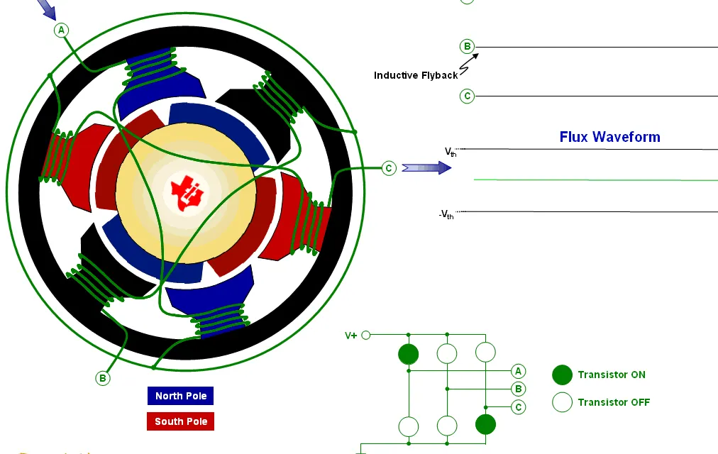
The BLDC operates on the same law as of a regular type. This type requires some coils to be energized to make the rotor rotate. The coils placed in the stator slots are named A, B, and C. When coil A is energized by a DC supply, it gets excited and attracts the rotor permanent magnet. Similarly, when coil B is energized rotor permanent magnet is attracted this continues when coil C is also energized. After coil C is energized, coil A is again energized but with negative polarity. This continues with the remaining coils as well with negative polarity. This cycle continues alternately and the rotor continuously rotates.
Solution:-
- the process for power H-Bridge-
- Open MATLAB then go to the help section.
- Then search for 'Speed control of a DC motor using BJT H-bridge’.
- After opening the model, run the model.
- record the scope current switching frequency and the IGBT current
- modify the frequency to 25% so the current does not go to its peek value
- Record the observation.
- The process for Four quadrant chopper-
- Open MATLAB then go to the help section
- Then search for ‘The Four-Quadrant Chopper DC Drive (DC7) block’.
- After opening the model run the model.
- record the observation from the scope.
- compare the model with the above experiment and tell your reasons for the output.
- The process for Four quadrant chopper-
- Open MATLAB then go to the help section
- Then search for ‘The Four-Quadrant Chopper DC Drive (DC7) block’.
- After opening the model run the model.
- Change the torque value.
- Change the step into a slider value.
- Change the battery because it is pure EV one
- Change the time to inf for better results
- Attach a display in the moto speed for comparison
- This does not have any process it is fully theory.
Observation:-
- the observations are:-
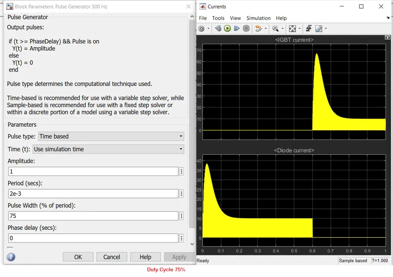
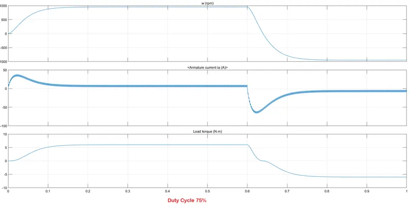
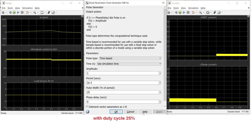
- The scope data is below
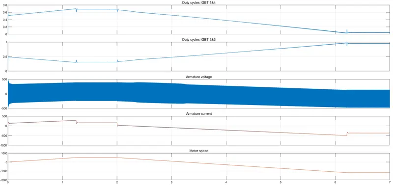
- this is the circuit diagram
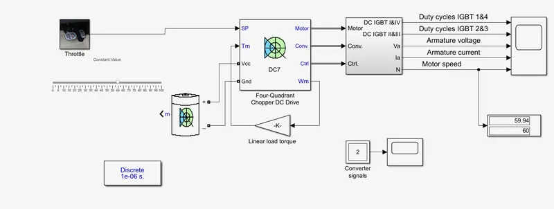
Conclusion:-
- We have seen that using Power electronics we can control the speed very easily and very efficiently and without any error and short-circuiting the circuit.
- The Four quadrant Chopper is very much effective because it has no switching required and it is very helpful as compared with the Bridge network.
- By changing it into inf time we can see the speed of the vehicle.