Week-7 Challenge: DC Motor Control
Aim :
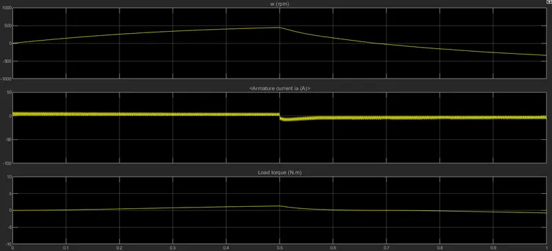
- Run MATLAB demo ‘Speed control of a DC motor using BJT H-bridge’. Modify the model such that armature current doesn’t shoot up when motor changes direction from forward to reverse.
Solution :
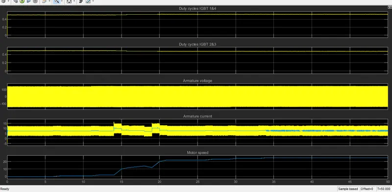
The following requirement is fulfilled by increasing the resistance of IGBT3 diode and also by decreasing the duty cycle to reduce the spike in armature current.
The changes hence made are represented here :
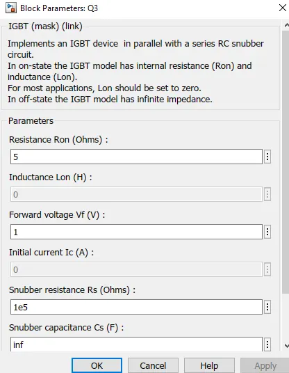
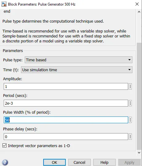
Hence the armature current after running the simulation looks like this :
2. Refer to help section of ‘The Four-Quadrant Chopper DC Drive (DC7) block’. Compare it with H-bridge model.
Solution :
H Bridge :
The H-Bridge block output is a controlled voltage that depends on the input signal at the PWM port. If the input signal has a value greater than the Enable threshold voltage parameter value, the H-Bridge block output is on and has a value equal to the value of the Output voltage amplitude parameter.
No forward voltage is modeled for the freewheeling diodes. They are approximated as ideal resistances when forward biased, with resistance equal to the Freewheeling diode on resistance parameter value.
DC7 Chopper :
The DC7 Chopper features closed-loop speed control with four-quadrant operation. The speed control loop outputs the reference armature current of the machine. Using a PI current controller, the chopper duty cycle corresponding to the commanded armature current is derived. This duty cycle is then compared with a sawtooth carrier signal to obtain the required PWM signals for the chopper.
The main advantage of this drive, compared with other DC drives, is that it can operate in all four quadrants (forward motoring, reverse regeneration, reverse motoring, and forward regeneration). In addition, due to the use of high switching frequency DC-DC converters, a lower armature current ripple (compared with thyristor-based DC drives) is obtained.
3. Make a suitable EV model using DC7 block and make result report.
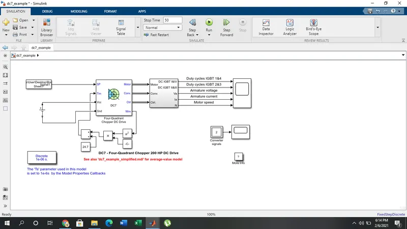
The detailed report is :