DC Motor Control
Question 1:
Run MATLAB demo ‘Speed control of a DC motor using BJT H-bridge’. Modify the model such that armature current doesn’t shoot up when motor changes direction from forward to reverse.
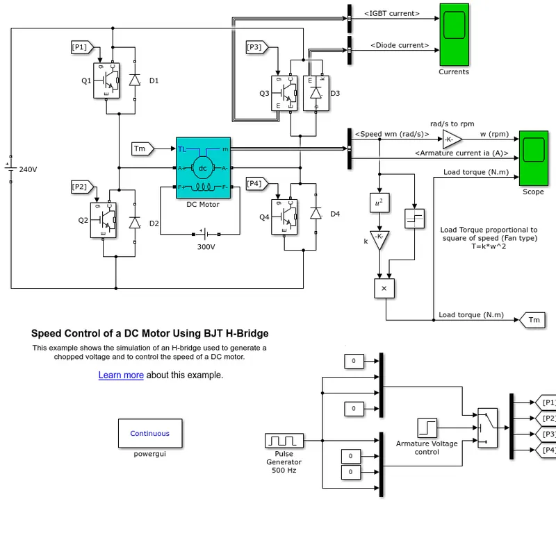
The above model is an example that shows the simulation of H-bridge used to generate a chopped voltage and to control the speed of a DC motor.
The DC motor used in this model has the following properties, 5HP 24V 1750 rpm. It simulates a fan type load (where Load torque is proportional to the square of speed).
The armature mean voltage can be varied from 0 to 240 V when the duty cycle (specified in the Pulse Generator block) is varied from 0 to 100%.
Working:
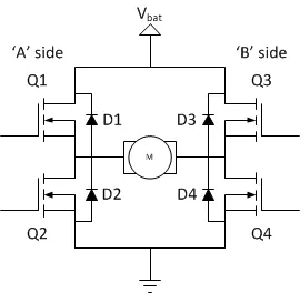
The H-bridge consists of four BJT/Diode pairs (BJT simulated by IGBT models). Two transistors are switched simultaneously: Q1 and Q4 or Q2 and Q3. When Q1 and Q4 are fired, a positive voltage is applied to the motor and diodes D2-D3 operate as free-wheeling diodes when Q1 and Q4 are switched off. When Q2 and Q3 are fired, a negative voltage is applied to the motor and diodes D1-D4 operate as free-wheeling diodes when Q2 and Q3 are switched off.
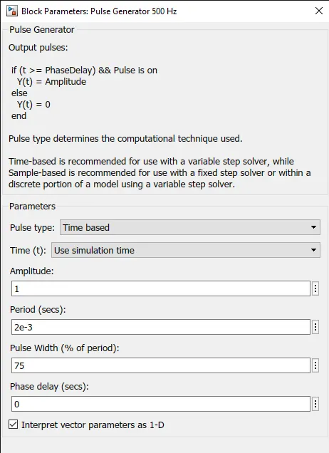
The motor starts in the positive direction with a duty cycle of 75% (mean DC voltage of 180V). At t= 0.5 sec., the armature voltage is suddenly reversed and the motor runs in the negative direction.
'Scope' shows motor speed, armature current and load torque and 'Currents' shows currents flowing in BJT Q3 and diode D3.
It can be clearly seen that the BJT is acting as a switch in which changing the parameters doesn't affect the output a lot. So the main parameter that affects the armature current shootup at 0.5 sec is from the pulse generator. It is provided that the initial conditions are set to 75% pulse width.
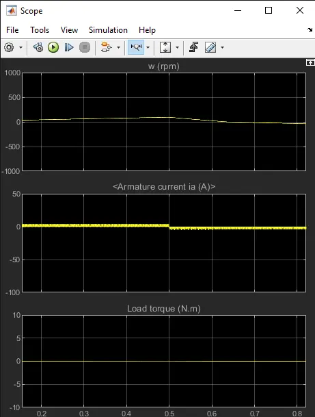
The obtained motor parameters over the period of 1sec with 0.5sec threshold are as follows:
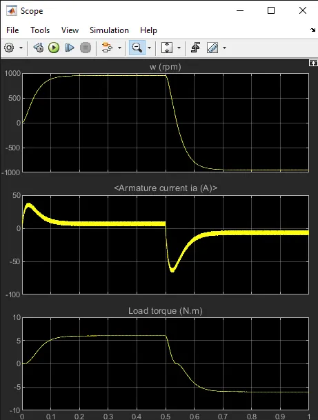
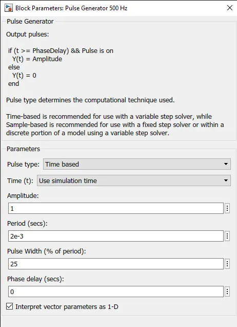
It can be seen at 0.5 th second the motor speed decreases and starts to rotate in the reverse direction. In this time we could find a shootup in armature current and then gets stabilised. Changing the pulse width significantly changes voltage thus reduces the armature current shootup when the motor runs in the reverse direction. Here after changing the pulse width to 25%, we could find the motor speed and load torque were reduced but it was not drastic compared to the prior cases. This in-turn lead to smooth change in armature current.
Question 2:
Refer to help section of ‘The Four-Quadrant Chopper DC Drive (DC7) block’. Compare it with H-bridge model.
| BJT H-BRIDGE DRIVE | FOUR QUADRANT CHOPPER DRIVE |
| It's used for changing the direction of the motor(forward and reverse) | Here the motor can be operated in four different modes (forward motoring & braking, reverse motoring and braking) |
| Regenearative braking is unavailable | Regenerative braking can be achieved |
| The source is fixed DC supply | The source is an AC supply whicj can be recified to varying DC supply |
| The motor speed reference cannot be fed | The motor speed reference can be fed |
| The armature ccurrent shoot up during phase transition | The armature current doesn't shoot up to value of BJT H-Bridge but for a negligible value |
| Used in robotics | Used in commercial applications |
H bridge
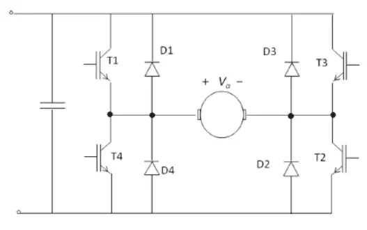
4 Quadrant Chopper
Question 3:
Make a suitable EV model using DC7 block and make result report.
The EV model is prepared based on the example model in the MATLAB documentation(DC7 four quadrant chopper 200 HP DC drive).
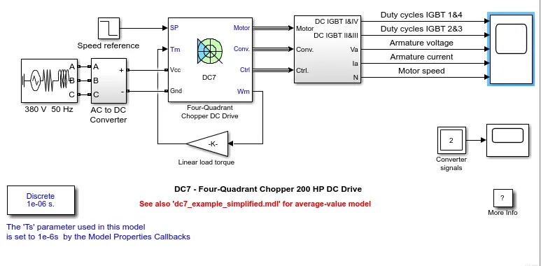
The reference speed is provided using step input and a 3 phase AC source is provided. As the 4 quadrant runs in varying DC supply, a AC to DC converter is used.
The 200 HP DC motor is separately excited with a constant 150 V DC field voltage source. The armature voltage is provided by an IGBT converter controlled by two PI regulators. The converter is fed by a 515 V DC bus obtained by rectification of a 380 V AC 50 Hz voltage source. In order to limit the DC bus voltage during dynamic braking mode, a braking chopper has been added between the diode rectifier and the DC7 block.
The first regulator is a speed regulator, followed by a current regulator. The speed regulator outputs the armature current reference (in p.u.) used by the current controller in order to obtain the electromagnetic torque needed to reach the desired speed.
The current regulator controls the armature current by computing the appropriate duty ratios of the 5 kHz pulses of the four IGBT devices (Pulse Width Modulation).
For proper system behaviour, the instantaneous pulse values of IGBT devices 1 and 4 are opposite to those of IGBT devices 2 and 3. This generates the average armature voltage needed to obtain the desired armature current. In order to limit the amplitude of the current oscillations, a smoothing inductance is placed in series with the armature circuit.
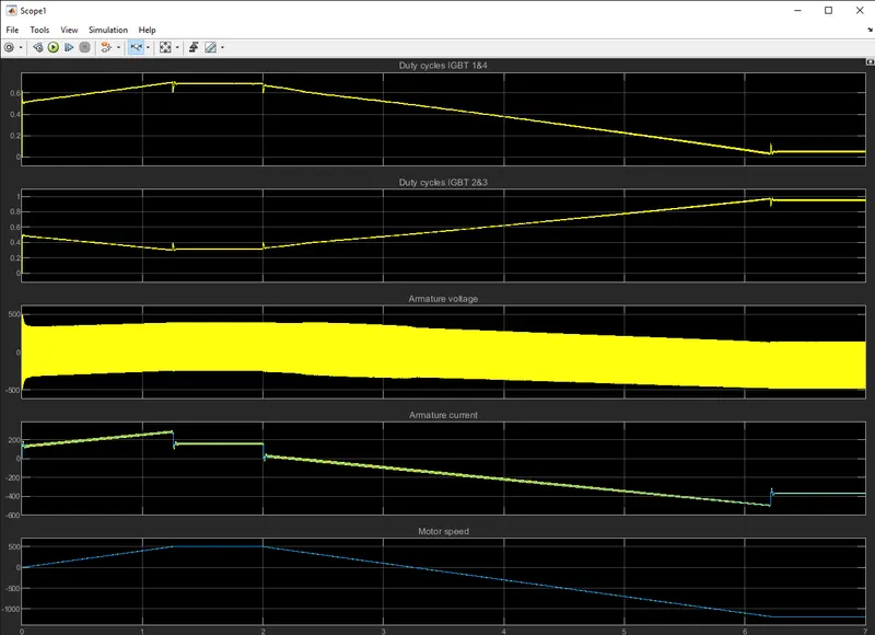
The motor is coupled to a linear load, therefore the mechanical torque of the load is proportional to the speed.
The speed reference is set at 500 rpm at t = 0 s.
The armature current follows the current reference very well, with fast response time and small ripples. Notice that the current ripple frequency is 5 kHz.
At t = 2 s, speed reference drops to -1184 rpm. The current reference decreases to reduce the electromagnetic torque and causes the motor to decelerate with the help of the load torque.
At t = 2.2 s, the current reverses in order to produce a braking electromagnetic torque (dynamic braking mode). This causes the DC bus voltage to increase.
At t = 3.25 s, the motor reaches 0 rpm and the load torque reverses and becomes negative. The negative current now produces an accelerating electromagnetic torque to allow the motor to follow the negative speed ramp (-400 rpm/s). At t = 6.3 s, the speed reaches -1184 rpm and stabilizes around its reference.