Week-7 Challenge: DC Motor Control
AIM:- To study DC motor control with the help of MATLAB and SIMULINK
OBJECTIVES:-
1)Running a MATLAB demo ‘Speed control of a DC motor using BJT H-bridge’ and modifying it such that the model such that armature current doesn’t shoot up when motor changes direction from forward to reverse.
2) Studying The Four-Quadrant Chopper DC Drive (DC7) block and comparing it with the H-bridge model.
3) Modeling an EV using DC7 block and making a result report.
*****************************************************************************************************Q.1.Run MATLAB demo ‘Speed control of a DC motor using BJT H-bridge’. Modify the model such that armature current doesn’t shoot up when motor changes direction from forward to reverse.
THEORY:-
How to Build an H bridge Circuit with Transistors
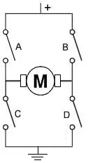
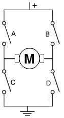
Fig 1.1 H-bridge with transistors
In this circuit, we will show how to build an H-bridge circuit with transistors.
An h bridge is a circuit that is used primarily to control motors; they allow for forward and reverse motion of the motors. Therefore, the motor can be utilized with its full bidirectional capability.
To build an H-bridge, the only option is not to use an IC chip for an H-bridge. You can also build it with discrete and simple components such as transistors and resistors.
Even though it's almost invariably simpler to use an IC to act as an H-bridge such as the popular L293 IC, there may be times you may want to design one yourself for various reasons. You may also just be interested in knowing how an h bridge works.
So in this circuit, we will build an H-bridge simply with bipolar junction transistors.
Since motors run off a good amount of current, we will use high-current gain and high-power transistors. These are transistors provide very good current gain and transistors that deal with a lot of power.
In total, we use 4 different transistors, 2 PNP transistors, and 2 NPN transistors.
The 2 types of transistors we will use are the TIP107 PNP transistors and the TIP102 NPN transistors. These are Darlington transistors that can deal with high power outputs. Again, since motors require a good amount of current, normally about 75mA or so, we want a high-power transistor. Motors require several times more current than an output device that says an LED would. We will talk about these transistors more.
Know that h bridges are useful for circuits that require bidirectional functioning. Otherwise, the only way to be able to operate the device bi-directionally would be to manually switch the polarity leads of the device. An H-bridge eliminates this need.
So, again, h bridges can be used for any type of bidirectional 2-lead device that works in opposite direction depending on which lead is connected to power. It's mostly for motors, but it can also be for other devices as well.
Components
- 2 TIP107/127 PNP transistors
- 2 TIP102/120 NPN transistors
- 4 1KΩ resistors
- 2 5.6KΩ resistors
- DC motor
Really any NPN transistors or PNP transistors can be used. But it is better for them to be high-power transistors since motors need adequate current.
The TIP107/127 transistors are PNP Darlington transistors.
Being that they are Darlington transistors, they provide high current gain. They also can deal with high power. The collector of the TIP107 transistor can deal with up to 80 watts of power, while the TIP127 can deal with up to 65W.
Being that the highest-rated DC motors are normally 12V, this means that the collector can pass 6.7A. Obviously, the motor requires nothing close to this. We need less than 100mA. So this transistor is well above the same range in power that we need.
The datasheets for the TIP107 or the TIP127 can be found at the following links: TIP107 PNP Datasheet and TIP127 PNP Datasheet.
The TIP102/TIP120 transistors are NPN Darlington transistors.
Being Darlington transistors, they also provide high current gain. This is good so that they can drive a high-power device such as a motor. The transistors themselves can deal with high power.
The datasheets for the TIP102 or the TIP120 can be found at the following links: TIP102 NPN Datasheet and TIP120 NPN Datasheet.
Again, you can really use any NPN or PNP transistors. High-power ones are better for this circuit, as motors need more, but you can mix and match and see what works.
The DC motor can be any type, of really any voltage. We are using a 6-12V DC power supply, so the maximum rating the motor should have is 12V. Normally, anyway, DC motors aren't rated higher than 12V, so you can use practically any motor.
Besides these, all we need else are a resistor.
H Bridge Circuit Built with Transistors
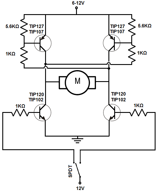
The h bridge circuit we will build with 4 bipolar transistors is shown below.
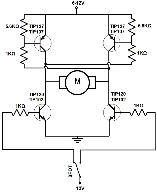
Fig 1.2 H bridge circuit 4 bipolar transistors
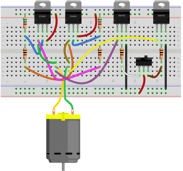
The breadboard circuit of the circuit above is shown below.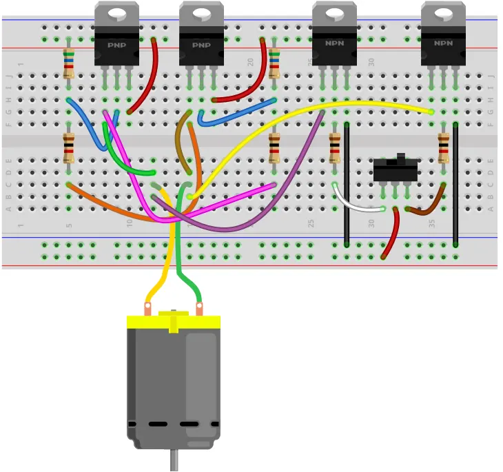
Fig 1.3 breadboard circuit of H bridge circuit 4 bipolar transistors
So the first thing that should be done is setting up power for the circuit. The circuit operates off of 6-12V, so it can run any type of motor. However, if you are using a much lower voltage-rated DC motor such as a 3V, you can use a lower voltage.
The circuit is manually controlled through a single pole double throw (SPDT) switch, a toggle switch.
The positive voltage either powers the base of the transistor on the left or the right. This transistor gets the positive voltage turns on.
This turns on the transistor on top of the other side.
Thus, if we turn on the left transistor, current flows from the right of the power source through the transistor on the top right, through the DC motor from right to left, and then from the left transistor to ground.
If we flip the toggle switch to the other side, the bottom right transistor will be powered on. This turns on the transistor at the top on the left side. Current flows from the power source, through the leftmost transistor at the top, through the DC motor, from left to right, and through the rightmost transistor and down to the ground.
Therefore, the circuit functions as an H-bridge.
If the switch is flipped one way, the motor spins in one direction.
If the switch is flipped the other way, the motor spins in the other direction.
So the circuit is able to achieve bidirectionality of the motor, as an h bridge should.
Normally, we would put diodes in reverse biased across the transistors. These diodes would help dampen transient spikes that are generated by the motor's coils so that they do not damage other components in the circuits. When a transistor stops running, it can create reverse emf, transient voltage spikes that can be large. To prevent them, reverse-biased diodes would stop these spikes from proceeding to other parts of the circuit, where they could cause damage. Being we're flipping the transistors on and off by flipping the toggle switch, you do want to have protection against back emf.
An SPDT switch is used for manual control to demonstrate how the circuit works. It is perfect because it only allows one of the NPN transistors to be on at any given time. Both transistors cannot be on at the same time because both transistors would have current flowing through, which is like a forbidden state. Therefore, it should be avoided. An SPDT switch avoids this condition.
The circuit, as is, will never be off unless the power supply is removed, being that the SPDT has no switch in which both transistors are grounded. To counter this, you could add a switch to the power supply so that the power supply disconnects from the circuit if this is desired.
If you don't want the circuit to be manually controlled by a switch, you can remove the SPDT switch and instead connect the base of the NPN transistors to whatever device you want to control it, such as a microcontroller. You still keep the 1KΩ resistors at the base.
Another thing is that this circuit, as if, puts the DC motor at one speed. To vary the speeds, instead of inputting a fixed DC voltage to the base of the transistors, a pulse width modulated signal would be applied to the base. We won't get into this article what value of PWM signal you would need to achieve a given speed, but you can take this approach to vary the speed of the DC motor. This is a far more efficient way than using a potentiometer to vary the speed, which is inefficient since it creates large power waste, though you can still use it.
So this is how an h bridge circuit can be built with transistors.
A)Running a MATLAB demo ‘Speed control of a DC motor using BJT H-bridge’
-first, we will open our model ‘Speed control of a DC motor using BJT H-bridge’ from Matlab help and we will be redirected to the Matlab 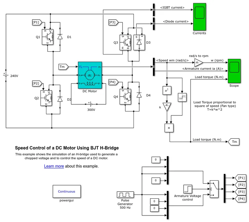
Power Electronics — Blocks
- By Category
- Alphabetical List
Switches
| Diode | Implement diode model |
| GTO | Implement gate turn off (GTO) thyristor model |
| Ideal Switch | Implement ideal switch device |
| IGBT | Implement insulated gate bipolar transistor (IGBT) |
| IGBT/Diode | Implements ideal IGBT, GTO, or MOSFET and antiparallel diode |
| MOSFET | Implement MOSFET model |
| Three-Level Bridge | Implement a three-level neutral point clamped (NPC) power converter with selectable topologies and power switching devices |
| Thyristor | Implement thyristor model |
| Universal Bridge | Implement universal power converter with selectable topologies and power electronic devices |
Converters
| Boost Converter | Implement boost power converter |
| Buck Converter | Implement buck power converter |
| Full-Bridge Converter | Implement full-bridge power converter |
| Full-Bridge MMC | Implement a full-bridge modular multilevel converter |
| Full-Bridge MMC (External DC Links) | Full-bridge MMC power converter with external DC connections |
| Half-Bridge Converter | Implement half-bridge power converter |
| Half-Bridge MMC | Implement a half-bridge modular multilevel converter |
| Three-Level NPC Converter | Implement three-phase, three-level Neutral-Point Clamped (NPC) power converter |
| Two-Level Converter | Implement three-phase two-level power converter |
| Two-Quadrant DC/DC Converter | Implement a two-quadrant DC/DC power converter |
specifications:-
motor power = 5 HP
voltage=240 v
speed=1750 RPM
The motor starts in the positive direction with a duty cycle of 75% (mean DC voltage of 180V). At t= 0.5 sec.
-after the model gets open in Simulink will run the simulation with default parameters like will keep our pulse generator with a 75 % duty cycle.
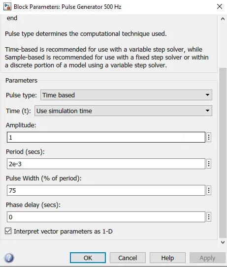
-run the simulation and will get our results after clicking on the scope block
OBSERVATIONS:-
-the first graph shows the IGBT current plot and diode current plots
- The given cycle runs for a 75 % duty cycle, which means the circuit is on for 75% of the time and off for 25% of cycle time.
- For the given plots we can see that for Q3 and Q4 the inputs are provided after 0.5 sec, so the IGBT signal is present after 0.5 sec to 1sec.
- As for the first cycle, we can see that the diode current passes, which indicates current passes through the circuit, and after 0.5 sec there is no diode current which indicates there is no current passes through the circuit or the current is flowing in a reverse direction.
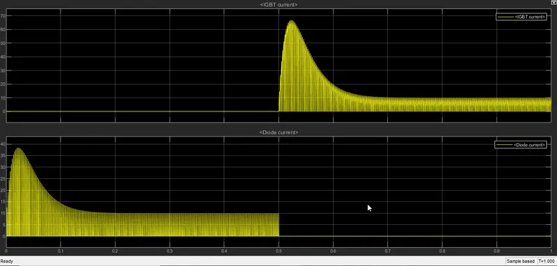
- and in another scope block after clicking on it will show us speed, armature current, and torque load plots
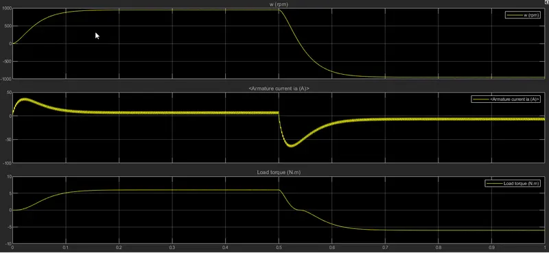
- from the given plot we can see that the motor took around 0.1 sec to reach the maximum rated speed it is because of the load applied
- in Q3 mode the motor starts reducing the speed or works in reverse mode and reaches a maximum speed of around 1000 rpm
- we can see that the armature current overshoots when it changes direction, due to the load applied and again reaches its constant current supply because of constant speed
in the second case, we will change our duty cycle percentage to see our results
Duty cycle 40%
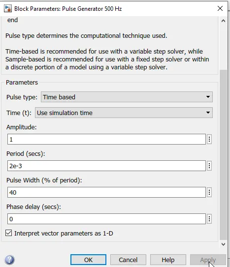
-and will run our simulation at the end of the simulation we can check our results in the scope window
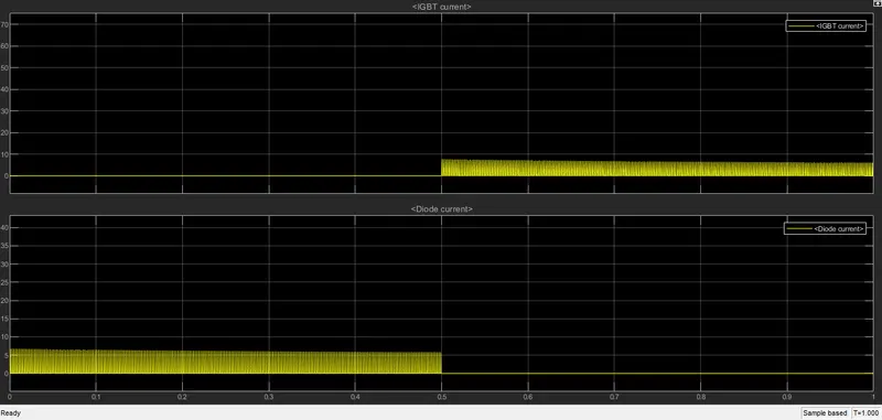
-the first graph shows the IGBT current plot and diode current plots
-we can see the uniform and smooth plot of diode current and IGBT current
-the first graph shows the IGBT current plot and diode current plots
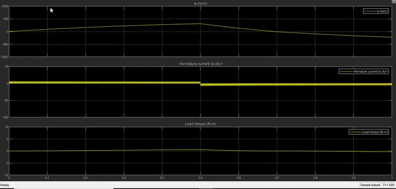
- and in another scope block after clicking on it will show us speed, armature current, and torque load plots
observations:-
we can see by changing the duty cycle to 40 % the shoot up of armature current when changing direction has been reduced
*****************************************************************************************
Q.2 Refer to the help section of ‘The Four-Quadrant Chopper DC Drive (DC7) block’. Compare it with the H-bridge model
DC7 - Four-Quadrant Chopper 200 HP DC Drive
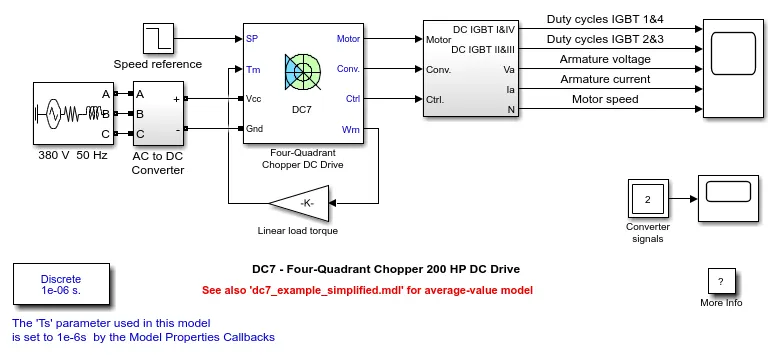
Description
The 200 HP DC motor is separately excited with a constant 150 V DC field voltage source. The armature voltage is provided by an IGBT converter controlled by two PI regulators. The converter is fed by a 515 V DC bus obtained by rectification of a 380 V AC 50 Hz voltage source. In order to limit the DC bus voltage during dynamic braking mode, a braking chopper has been added between the diode rectifier and the DC7 block.
The first regulator is a speed regulator, followed by a current regulator. The speed regulator outputs the armature current reference (in p.u.) used by the current controller in order to obtain the electromagnetic torque needed to reach the desired speed. The speed reference change rate follows acceleration and deceleration ramps in order to avoid sudden reference changes that could cause armature over-current and destabilize the system. The current regulator controls the armature current by computing the appropriate duty ratios of the 5 kHz pulses of the four IGBT devices (Pulse Width Modulation). For proper system behavior, the instantaneous pulse values of IGBT devices 1 and 4 are opposite to those of IGBT devices 2 and 3. This generates the average armature voltage needed to obtain the desired armature current. In order to limit the amplitude of the current oscillations, a smoothing inductance is placed in series with the armature circuit.
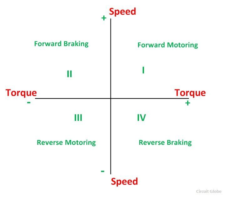
The figure below shows the four-quadrant operation of drives:
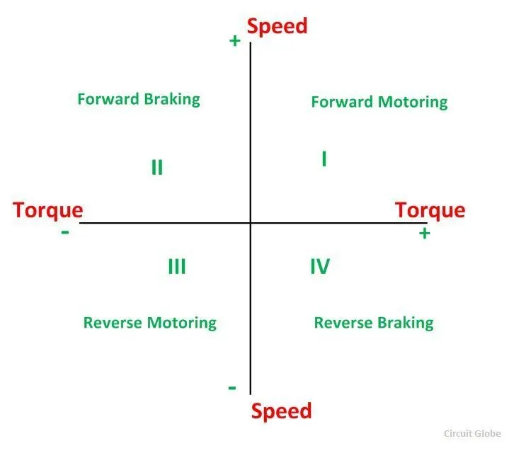
Fig 1.4 four-quadrant operation of drives
Compare The Four-Quadrant Chopper DC Drive (DC7) block with H-bridge mode
| Sr no | BJT-H BRIDGE MODEL | DC-7 Drive |
| 1 | Operates in 1st and 3rd quadrant(forward motoring and reverse motoring | Operates on all 4 quadrants(Forward motoring and breaking and Reverse motoring and breaking |
| 2 | Closed-loop chopper i.e takes feedback from the output to change the input | Open-loop chopper |
| 3 | Armature current oscillations are reduced by a smoothing inductance connected in the series with the armature circuit | Never lower duty cycles for reducing armature current ripples |
| 4 | PI controllers are used for dynamic control of pulse width | We provide a pulse value of fixed width for the simulation, as there is no feedback in the circuit |
| 5 | Continuous computation requires extensive computation. | Discrete computation for the model, hence quick. |
***************************************************************************************************
Q.3 Make a suitable EV model using the DC7 block and make a result report.
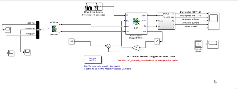
-first, we will open the dc 7 block in Simulink with the Matlab help section after opening the model we will redirect to Simulink
-after we will modify this block to design our EV model
-first, we will change the speed refrence block to drive cycle block
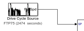
-to design EV MODEL we need first of all a source it can be normally DC source or we can add a battery from the Simulink library browser
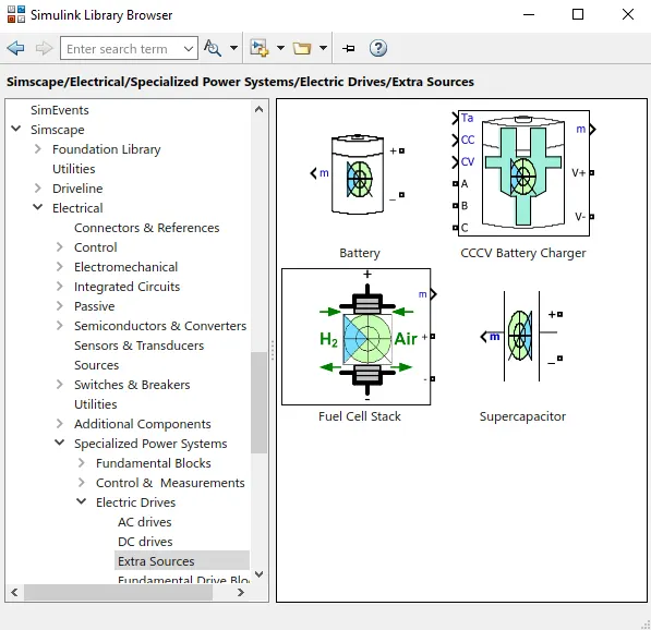
-after adding the battery to plot battery current, voltage and soc will connect a battery to the bus selector
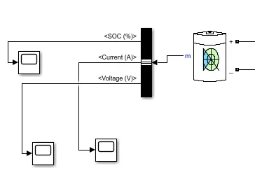
and bus selector outputs to the scope window so we can observe the current, voltage, and soc output plots.
-after that, we will convert linear load torque into new custom blocks for the torque motor equation

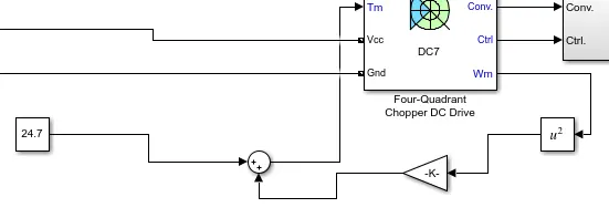
-after all the modification the final EV model will look like this
- after running this model we will get our result in scope block
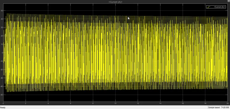
the first scope is the current scope which indicates the battery current fluctuations
-the second scope is voltage scope which is the battery voltage plot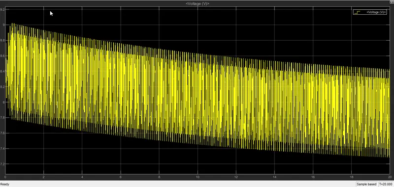
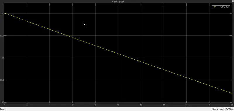
-the third scope is soc which indicates battery state of charge in percentage
And our final scope contains,
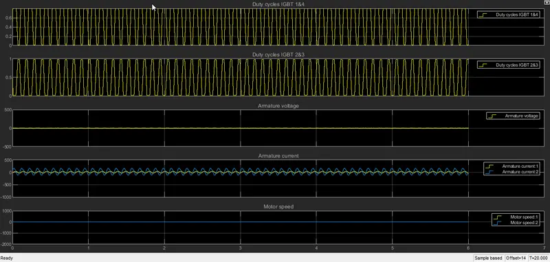
observations:-
-final graph contains results contain plots of duty cycle IGBT 1st & 4th quadrant and plot of duty cycle IGBT 2nd and 3rd quadrants.
-the remaining plots are armature voltage, armature current, and motor speed.
-the cycle time is t=20 sec the IGBT plots fluctuate uniformly from both positive and negative.
- there is no armature reaction and armature voltage drop, the voltage will remain constant for any load current. that's why we are getting a straight line.
-the armature current line contains yellow line and blue line which are the actual path and trace path lines which are fluctuating continuously due to change in load.
-motor speed plot is a straight line which is the ideal characteristic of a motor.
CONCLUSION:-
Thus we have studied both BJT-H drive and The Four-Quadrant Chopper DC Drive (DC7) block model also compared them and design EV model using DC7 block,
REFERENCES:-
1) Fig 1.1 H-bridge with transistors:-http://www.learningaboutelectronics.com/images/H-bridge.png
2) Fig 1.2 H bridge circuit 4 bipolar transistors:- http://www.learningaboutelectronics.com/images/H-bridge-circuit-with-transistors.png
3) Fig 1.3 breadboard circuit of H bridge circuit 4 bipolar transistors:-http://www.learningaboutelectronics.com/images/H-bridge-breadboard-circuit-with-transistors.png
4) Fig 1.4 four-quadrant operation of drives:-https://circuitglobe.com/wp-content/uploads/2015/12/four-quadrant-operatio-fig-compressor.jpg
5) The power electronics blocks of switches and converter tables:-https://in.mathworks.com/help/physmod/sps/referencelist.html?type=block&category=power-electronics&s_tid=CRUX_topnav
(Note:- The design EV model block file is each attach below)