Week 7 Challenge - Assembly Workbench
ASSEMBLY WORKBENCH
- ASSEMBLY WORKBENCH :-
Assembly workbench is one of the most powerful workbench in CATIA for th reason that components that are designed in multiple workbenches gets assembled here . typically a car is made of 30000 parts from small nuts to tyres and this cannot be made into a single product without the help of assembly workbench. we can also perform various analyses like clash clearance, dependencies & degree of freedom in this workbench . let us see a overview of types of constraints and methods of apply them in this articles.
TO ENTER THE ASSEMBLY WORKBENCH START > MECHANICAL DESIGN > ASSEMBLY DESIGN
- WHAT IS THE USE OF PUBLICATION IN CATIA V5 :-
publication in CATIA is a method to flag and name certain geometry inCATIA. generally, published geometry is referenced (copied with a link) to other CAT part files, in a relational design scenario.
one of the benefits of using publications is that it updates the child parts when the publications is that it updates the child parts when the published geometry is replaced in the parent part.
for example:- you have a cad containing master geometry to control other parts within the assembly.
this master file contains several parallel planes. the plane in the center of the assembly is published as the '' CENTER PLAN '' and it is referenced on several components so every one knows and designs their parts based on this center plane. now , half way through the design process , the width of the assembly changes and a new plane is added at th new center . by changing the publication and replaing the old plane with the new plane and renaming the new plane ''CENTER PLANE '' all th component parts are automatically modified.
- PRODUCT STRUCTURE TOOLS IN ASSEMBLY WORKBENCH :-
- INSERT NEW COMPONENT
- INSERT NEW PRODUCT
- INSERT NEW PART
- INSERT EXISTING COMPONENT
- REPLACE COMPONENT
- REORDER TREE
- CONSTRAINTS IN ASSEMBLY WORKBECH :-
CONSTRAINTS ALLOW you to position mechanical components correctly in relation to the other components of the assembly . you can see the constraints tool bar in any typical assembly workbench, if it is not visible try to restore all the positions of the tool bars. you can also navigate to view tool bars and then select the constraints toolbar.
- FIX CONSTRAINT
- COINCIDENCE CONSTRAINT
- CONTACT CONSTRAINT
- OFFSET CONSTRAINT
- ANGLE CONSTRAINT
- FIX TOGETHER
- QUICK CONSTRAINT
- DEFINITION OF DRAFTING :-
Drafting is also spelled as draughting , also called as engineering drawing .
Drafting is the process of representing on object or idea by means of lines having various thicknesses and makeups.
- CLASSIFICATION OF DRAFTING:-
- BASED ON THE USAGES OF DRAFTING
- FURNITURE DRAFTING
- ARCHITECTURAL DRAFTING
- MECHANICAL OR MACHINE DRAFTING
- ELECTRIAL AND ELECTRONICS DRAFTING
- STRUCTURAL DRAFTING AND SHEET METAL DRAFTING etc.
2. BASED OF THE FUNCTION OF DRAFTING
- MANUAL DRAFTING
- COMPUTER AIDED DRAFTING OR DESIGNING
- ADVANTAGE OF MANUAL DRAFTING :-
- LOW COST DRAFTING EQUIPMENT
- NO CUTTING END TECHNOLOGY REQUIRED
- NO NEED SUBSCRIPTION
- NO TRAINING REQUIRED
- ADVANTAGE OF CAD DRAFTING:-
- QUALITY OF DESIGN
- EASY FOR DOCUMENTATION
- MODIFY AND REPRODUCE FASTER
- ABILITY TO CREATE A DRAWING FROM 3D MODELS
- FOLLOWING THE STANDARDS
- TIME CONSUMPTION
- USE OF PROJECTION IN DRAFTING:-
Projection is used to represent the complec 3D object in the 2D drawing sheet. projection is used to show the shape and size of the object in the Drawing or Draftinng sheet.
- TYPE OF PROJECTIONS IN DRAFTING :-
- PARALLEL PROJECTION
- PERSPECTIVE PROJECTION
1. PARALLEL PROJECTION :-
1. ORTHOGRAPHIC PROJECTION -
a. MULTIVIEW-
1. FIRST ANGLE PROJECTION
2. THIRD ANGLE PROJECTION
b.AXONOMETRIC -
1. ISOMETRIC
2. DIMETRIC
3. TRIMETRIC
2.OBLIQUE PROJECTION :-
a. CABINET PROJECTION
b. CLINOGRAPHIC PROJECTION
c. CAVALIER PROJECTION
2.PERSPECTIVE PROJECTION :-
- ONE POINT
- TWO POINT
- THREE POINT
- DRAFTING IN CATIA V5 SOFTWARE
First of all we will open the part body of the one whose drafting is to be done.
NEXT IS go to start then select mechanical design then next choise drafting
next select sheet size and ok then you in working sheet
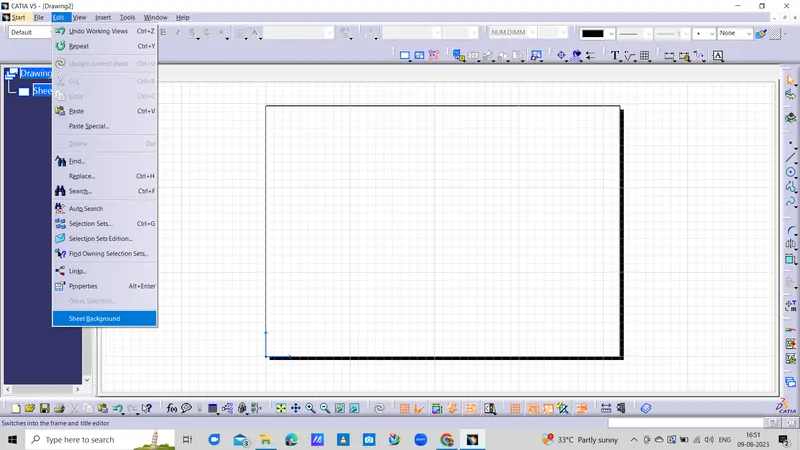
1st importing FRAMME AND TITLE BLOCK - once it is done ,noe=w we can import the framee and title block for both sheets. this cannot be inserted if we are in a working view for that we need to switch to the sheet back ground
for switching to sheet background , we need to select edit>sheet background
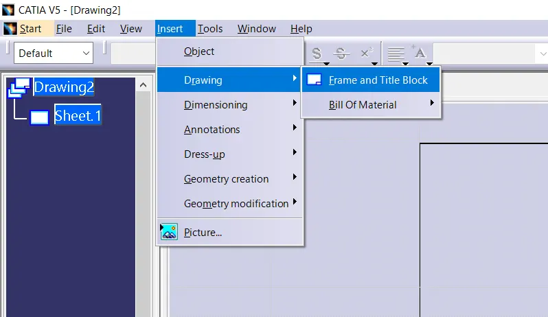
once you are inside the sheet background click on insert > drawing > frame and title block
in the manage frame and title block , select a suitable style from style of title block drop down list and click apply , ok
- ASSEMBLY WORKBENCH IN CATIA V5 SOFTWARE :-
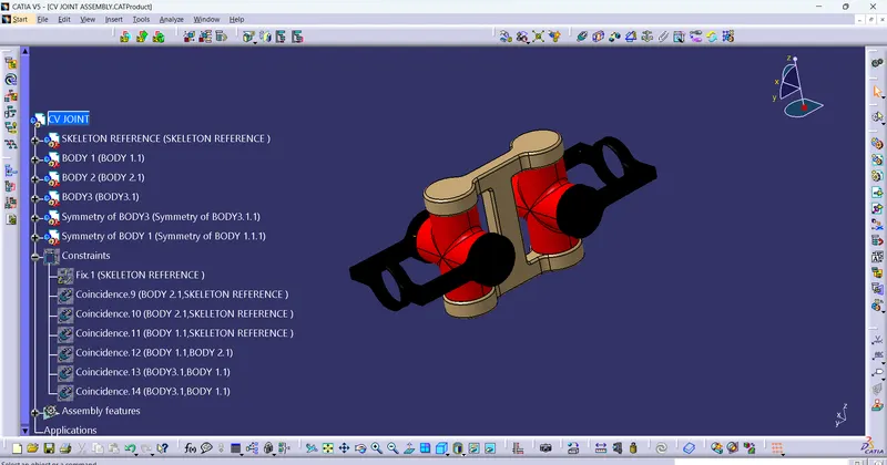
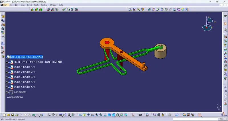
THIS CHALLENGE IN TWO PART ASSEMBLY
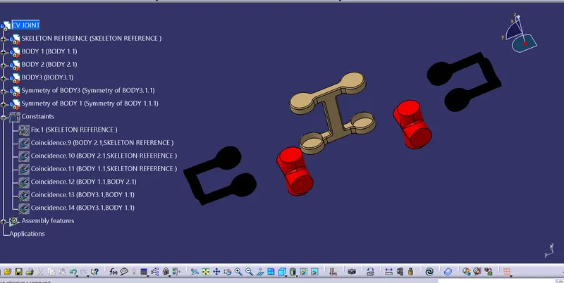
- CV JOINT
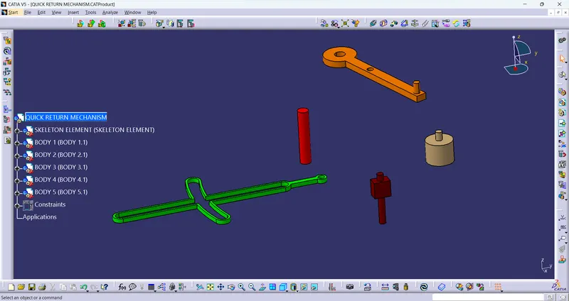
- QUICK RETURN MECHANISM
THIS ASSEMBLLY MADE WITH SOME PARTS
- CV JOINT
2. QUICK RETURN MECHANISM
- HOW TO CHECK YOUR ASSEMBLY IS PROPERLY CONSTRAINTS :-
OUR ASSEMBLY IS PROPERLY CONSTRAINTS SO CHECKED BY EXPLODE TOOL
- NOW if we need to check any of the missing constraints, we just need to explode them.
- male sure that product 1 is selected. now just click on apply and ok. also click yes to the warning that says you are about to modify product position.
- now if you update the entire product using all, the parts that are constrained properly will come back to its original position. the ones that are not constrained properly, they will not move back to its previous position.
- here all the [arts went back to its original position. this means, all the necessary constraints were added to assembly .
NORMAL VIEW
EXPLODE VIEW