Week 7 Challenge - Assembly Workbench
ASSEMBLY OF QUICK RETURN MECHANISM
Part required for quick return mechanism
Body 1
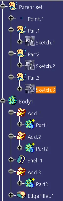
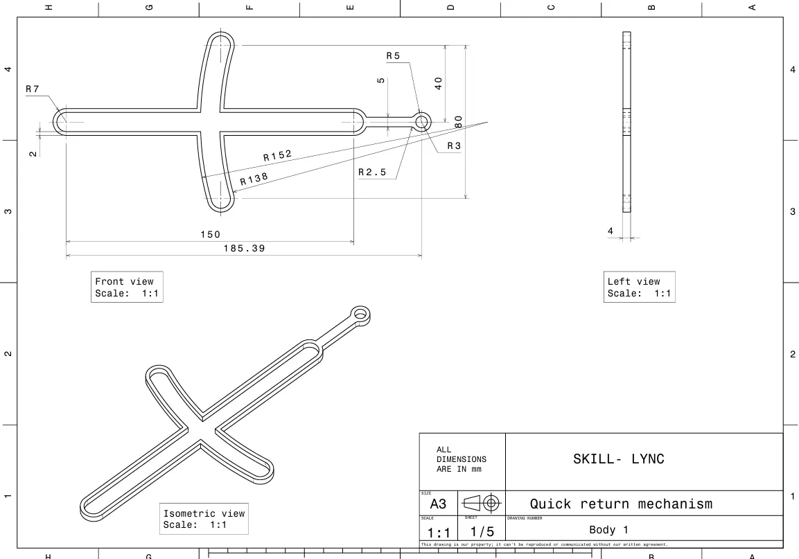
- 3 separate parts of the body are sketched as per specifications in the sheets.
- Boolean addition is used to merge the first and second part.
- Shell command used to give thickness of 2mm.
- Third part is merged using boolean addition to the previous body.
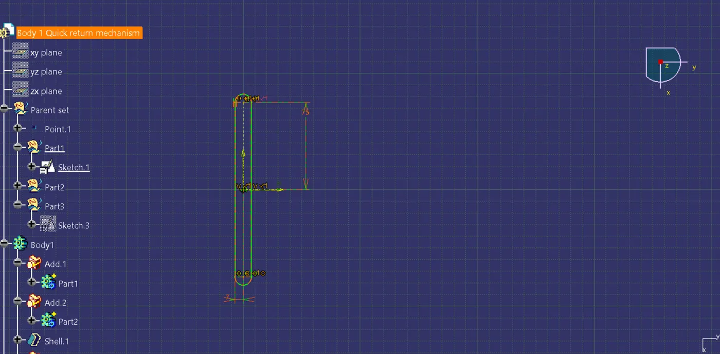
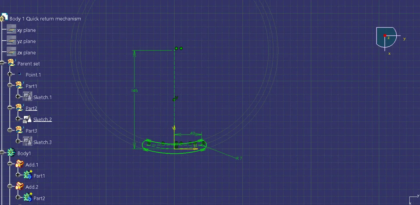
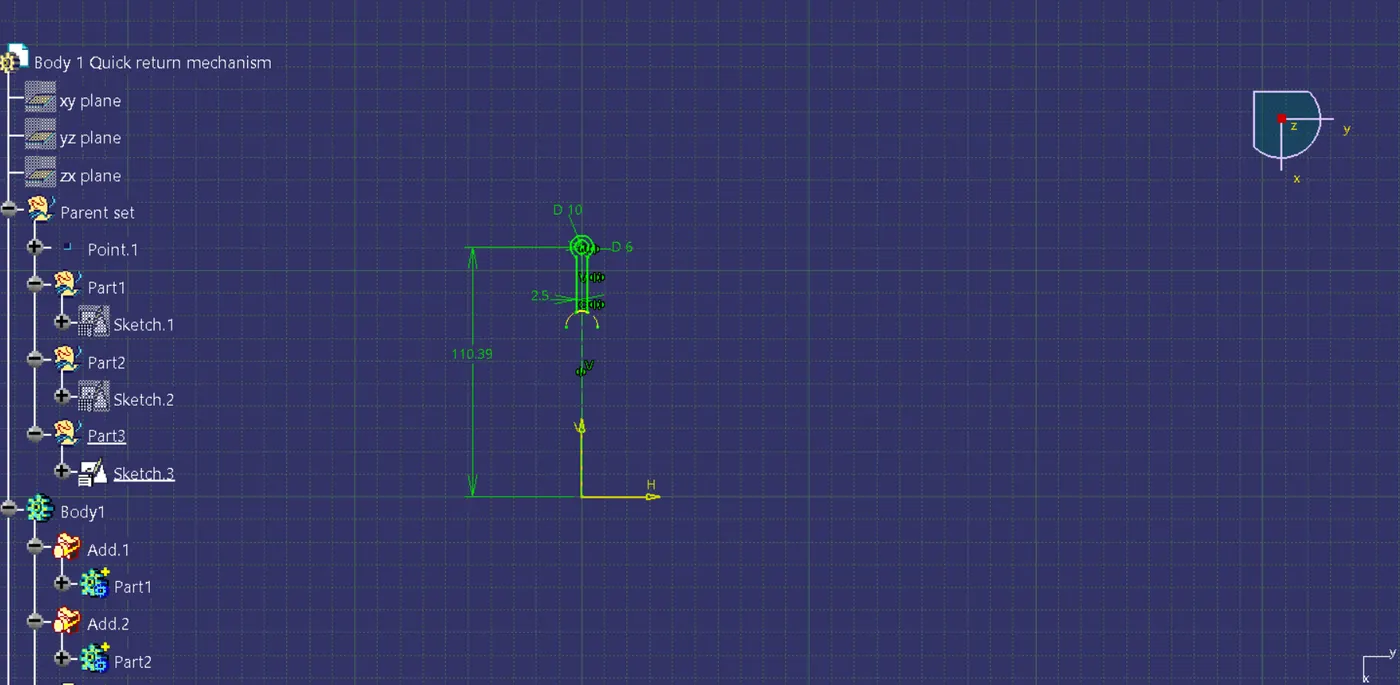
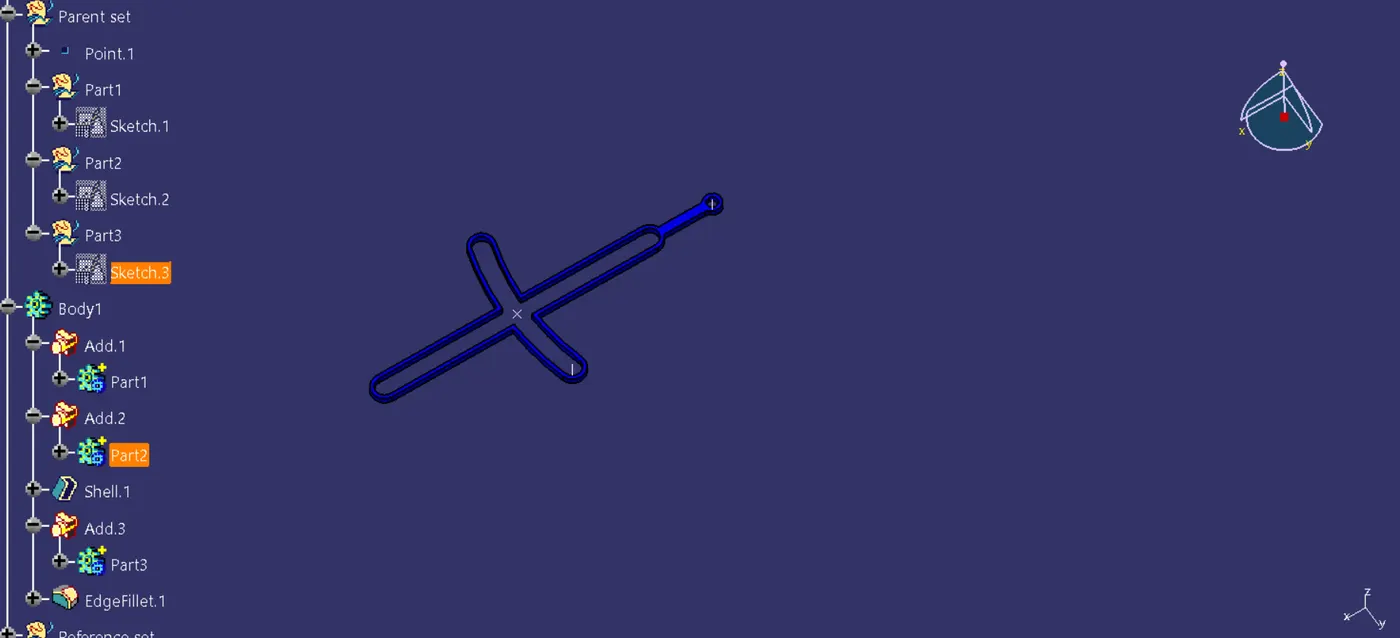
Tree structure of body 1:
Body 2
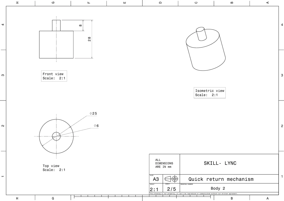
- Sketches are drawn for two circles at 6 mm and 25mm diameter each.
- Multipad command is used to extrude the profiles upto 28mm and 20mm from base to form the part.
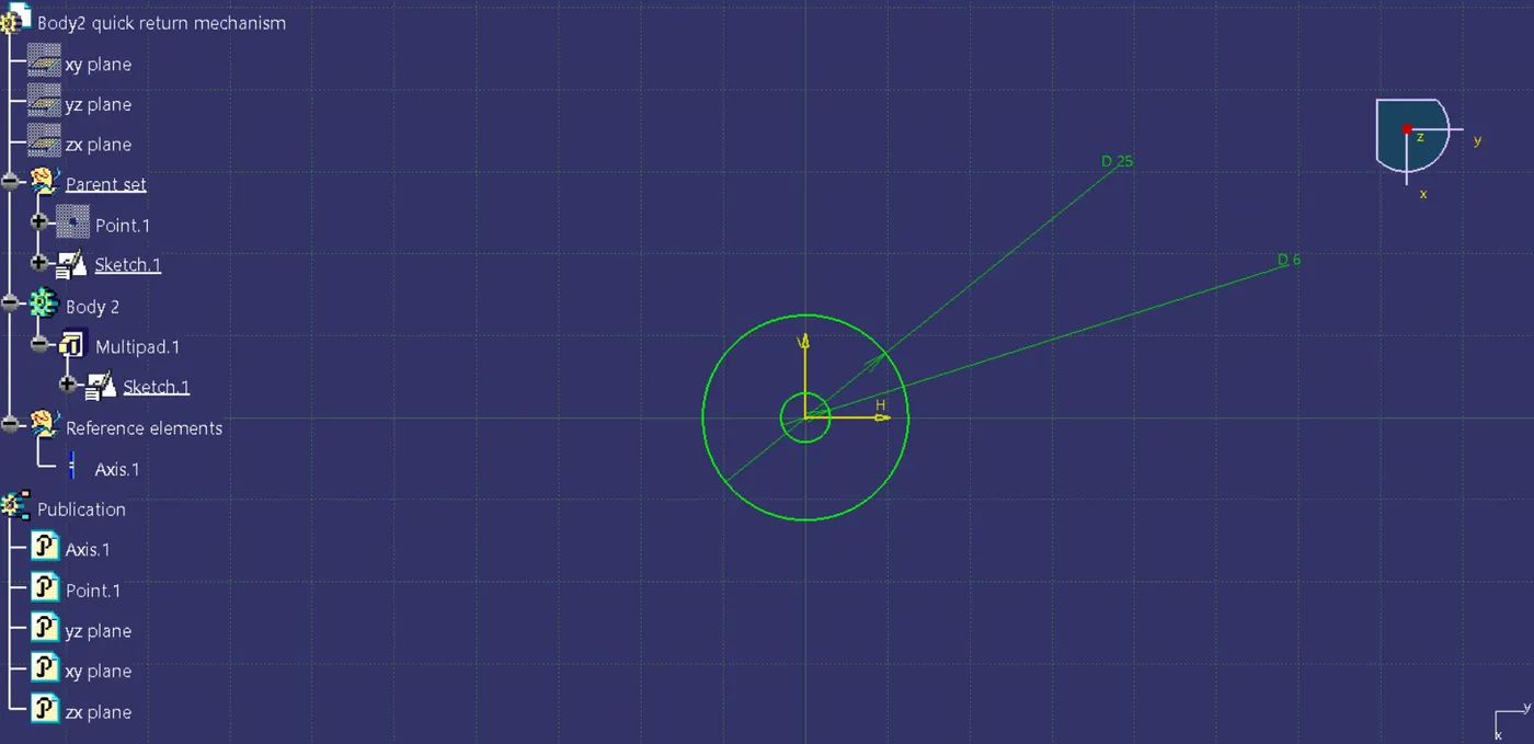
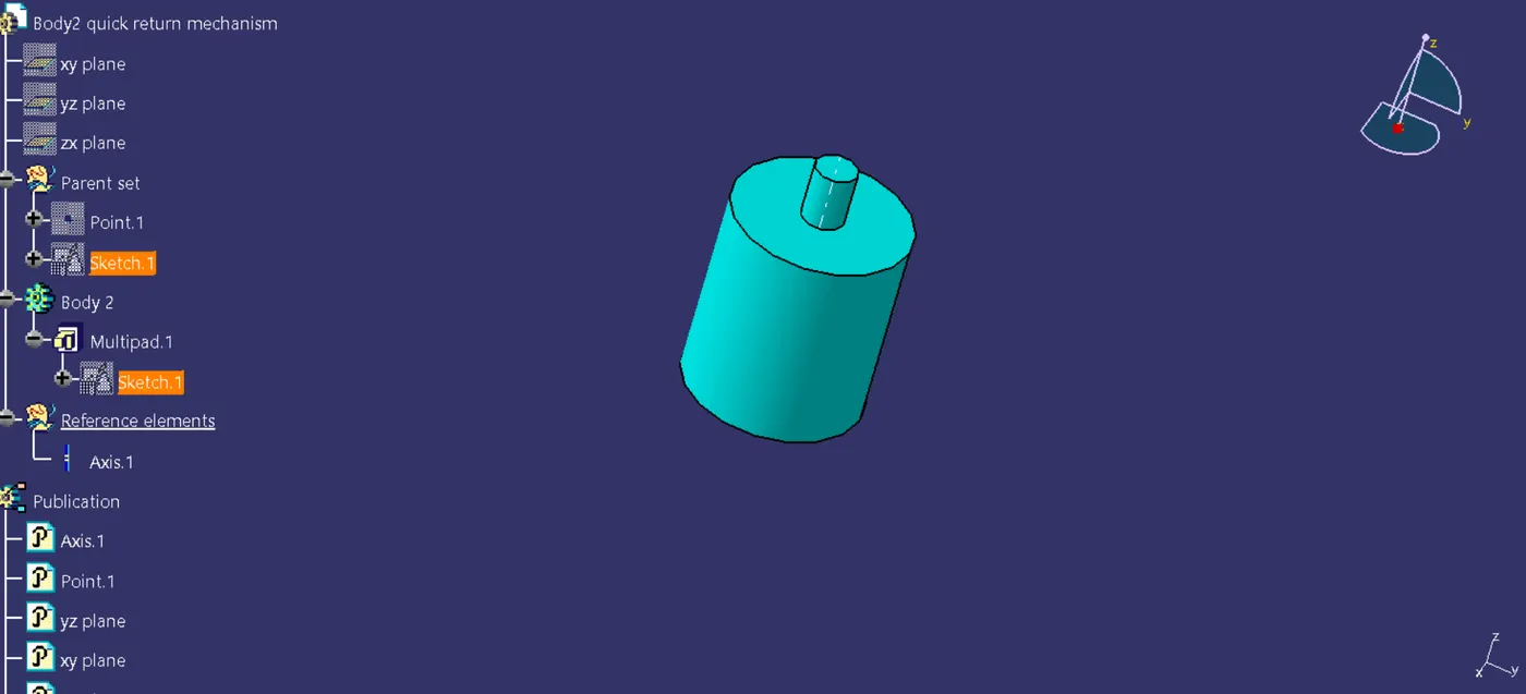
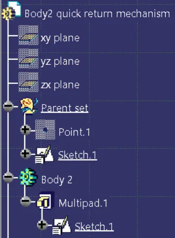
Tree structure for body 2:
Body 3
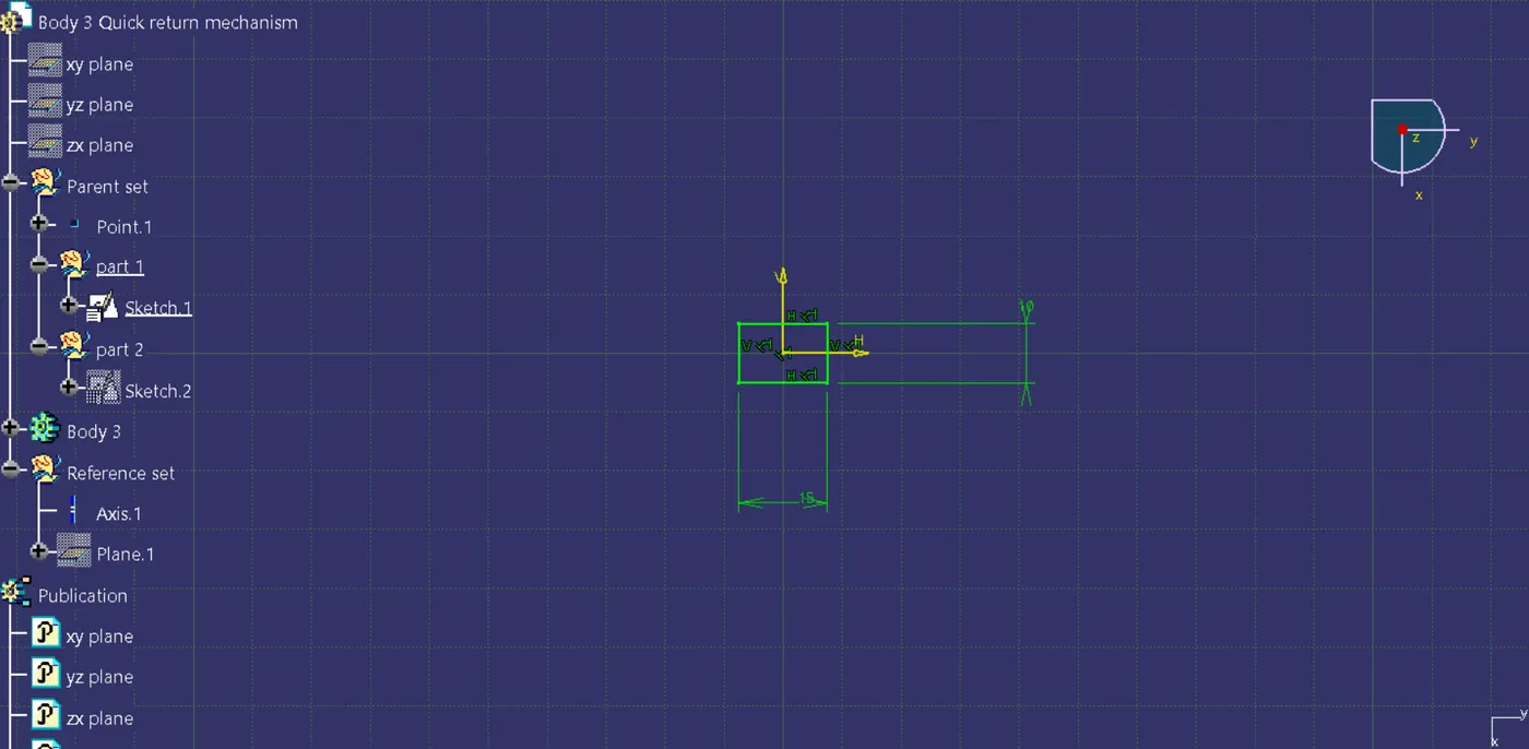
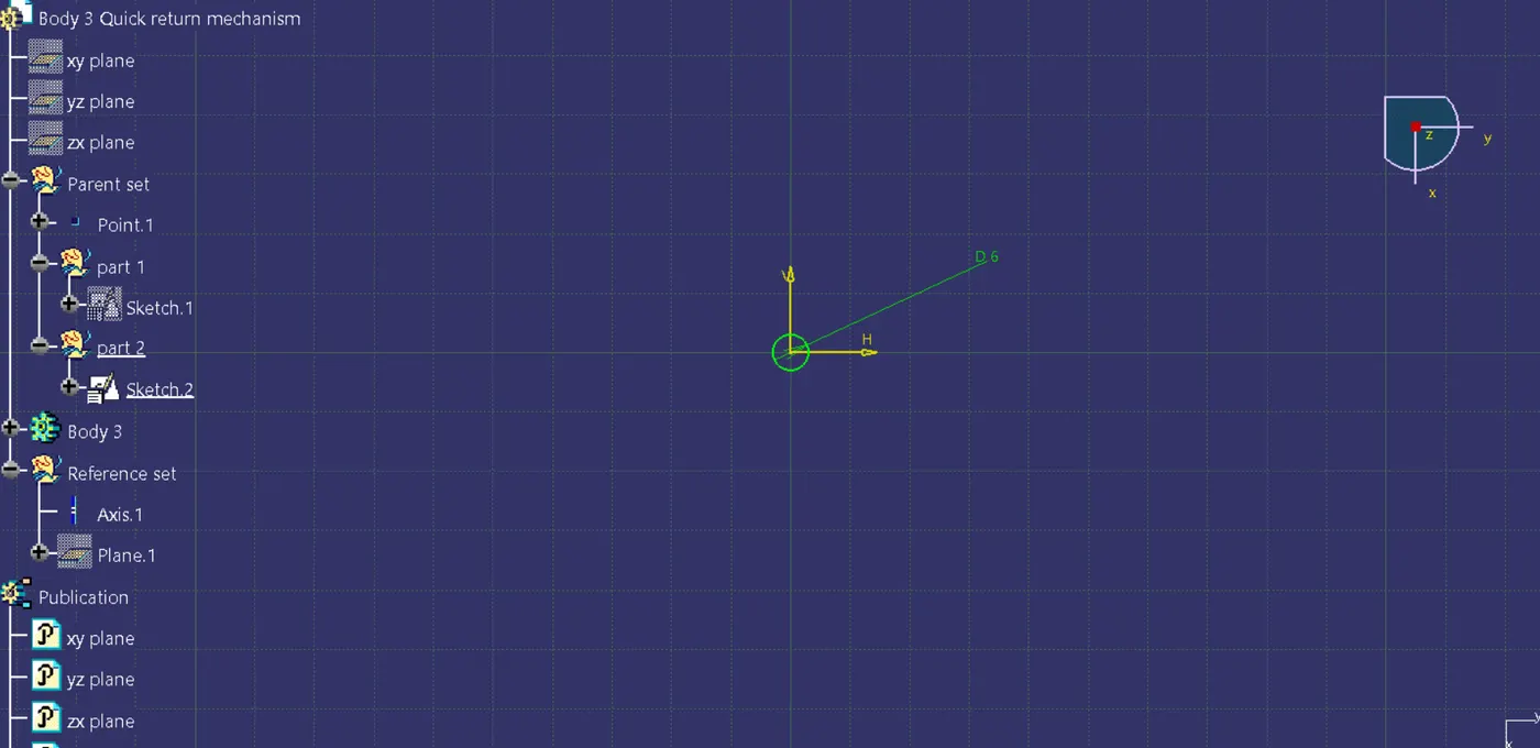
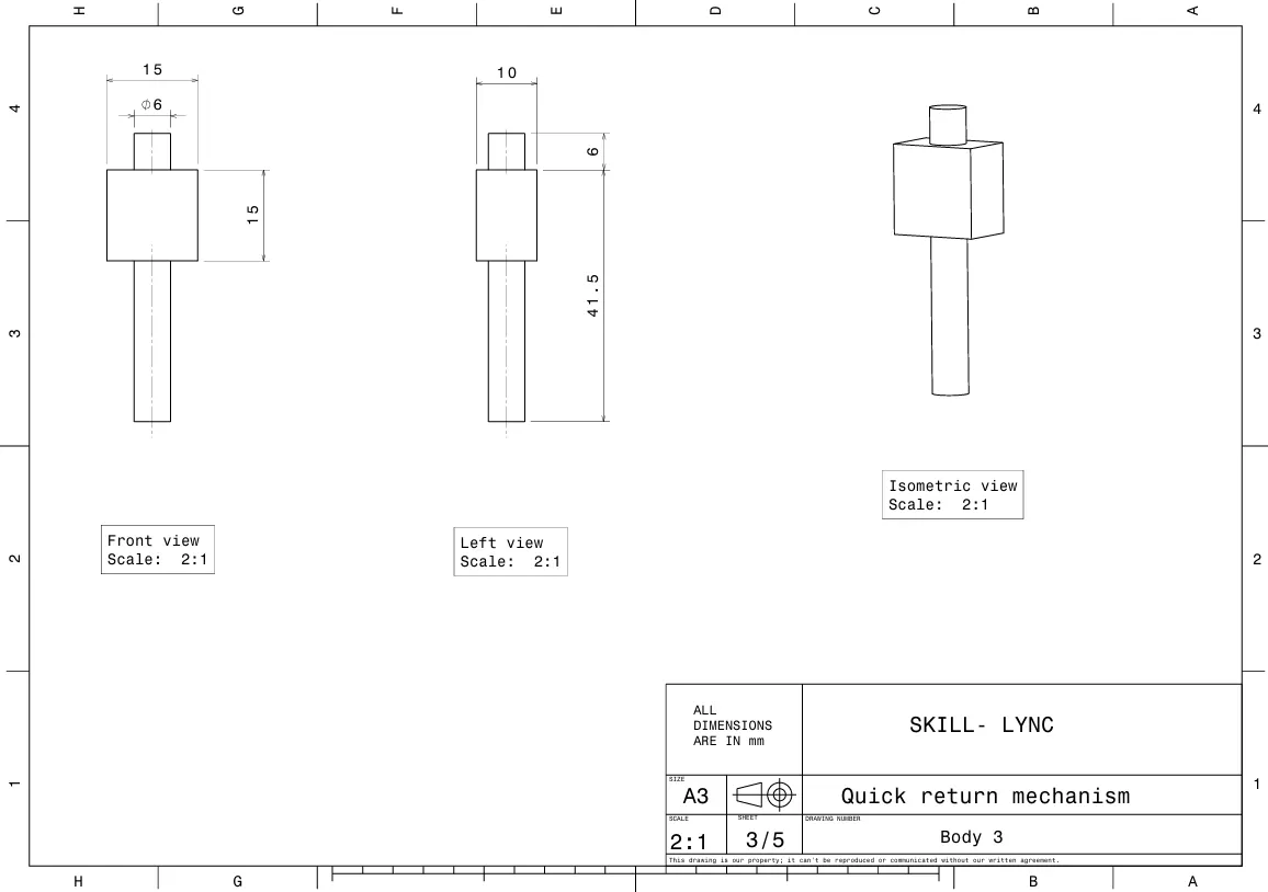
- Two separate sketches are made for the cuboidal and cylindrical surfaces.
- sketches are made as per dimensions provided.
- First part is extruded 15mm using pad command in upwards direction from reference plane XY.
- Second part is extruded 21mm upwards and 26.5mm downwards from reference plane XY
- The two parts are merged together using boolean addition.
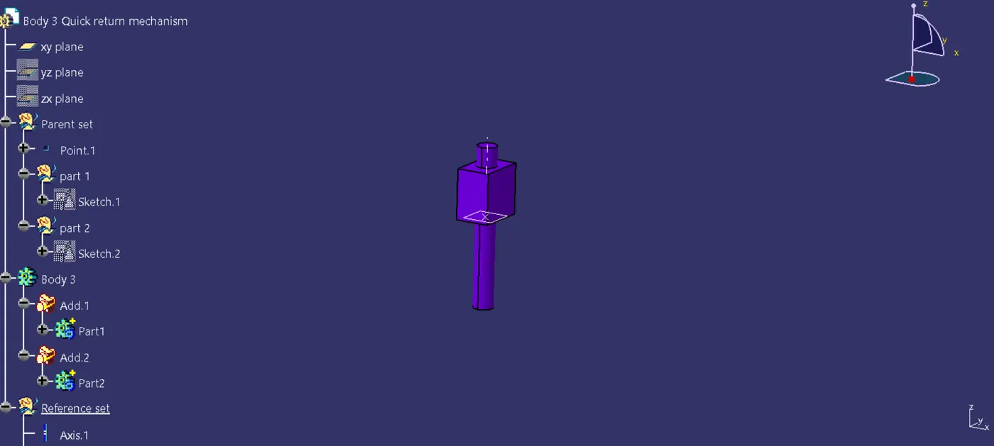
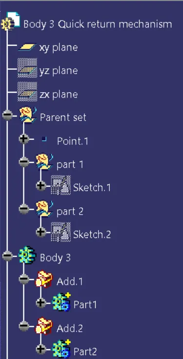
Tree structure for body 3:
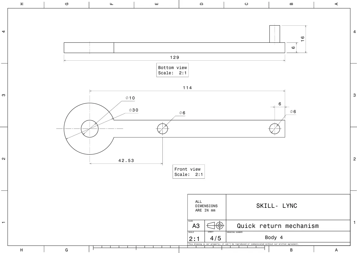
Body 4
- Here two separate sketches according to specifications on sheet.
- These sketches are made into two separate bodies.
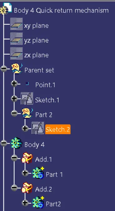
- The bodies are merged together using boolean addition.
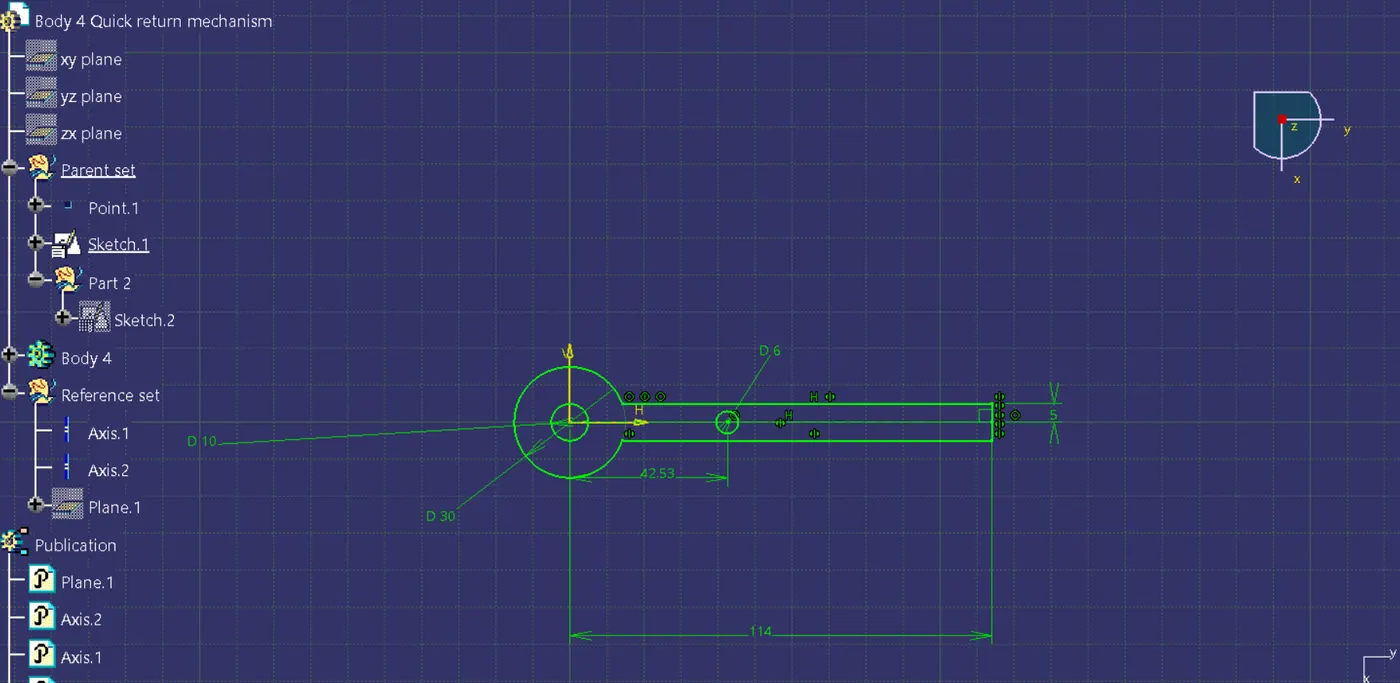
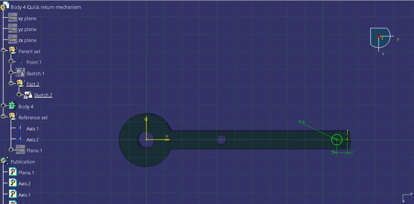
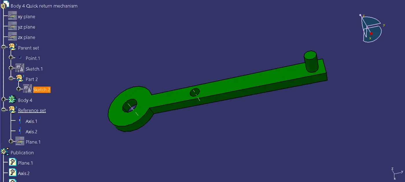
Tree structure for body 4:
Body 5
- For this part a single sketch of 10mm diameter is drawn.
- This is extruded to form a body using pad command.
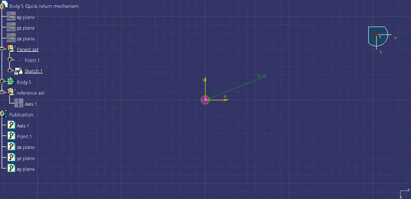
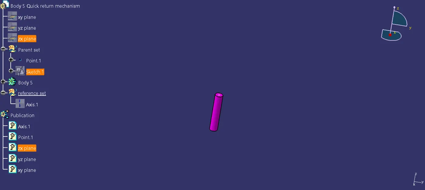
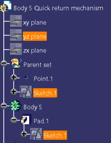
Tree structure for body 5:
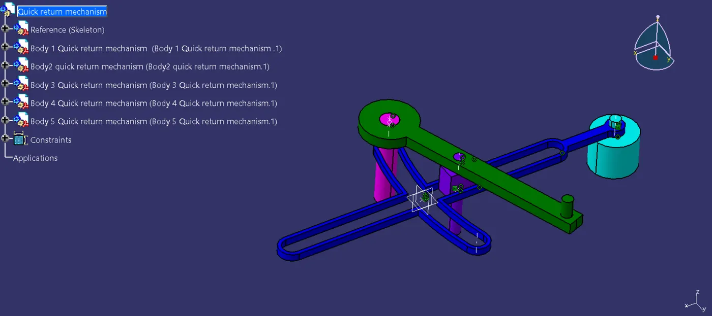
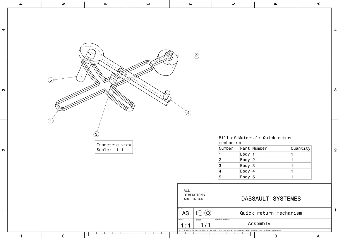
Assembly of quick return mechanism
- New product file is opened for creating the assembly.
- All the five bodies required for the assembly are imported to the file using existing component command.
- New body is created inside the assembly file for reference/ skeleton for the whole assembly.
- The reference is fixed at origin with 3 planes and point at origin.
- All the bodies required for the assembly are given respective reference sets inside each of them. These reference are used to provide constrains with others to complete the assembly.
- The created references are published.
- The bodies are roughly oriented in their positions using manipulation command.
- The published references are used to connect each other bodies with help of multiple constraints.
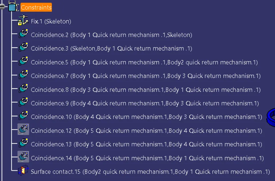
Drafting of the components

CV JOINT
Parts required for CV joint
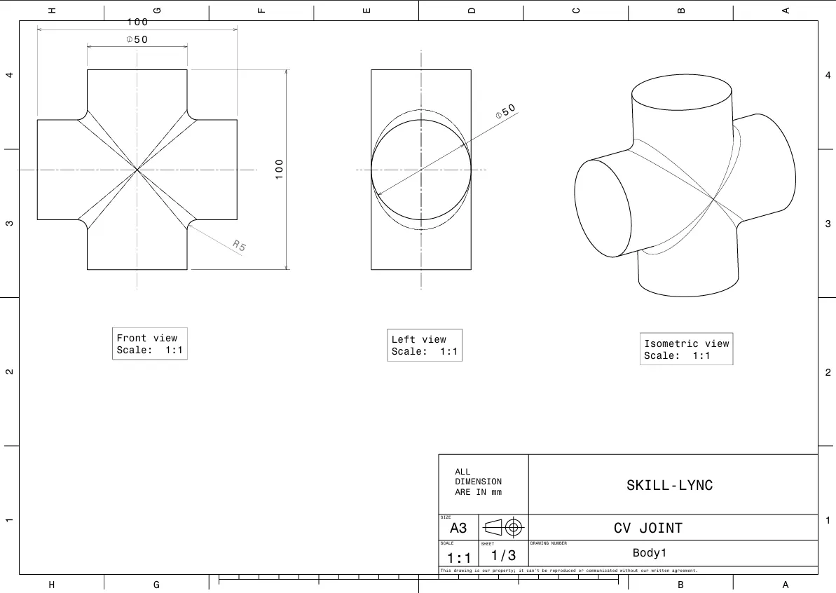
- Body 1
- Two separate sketches are made on XZ and YZ planes of circular profile having 50mm diameter.
- These two sketches are extruded using pad command for 100mm intersecting each other.
- These two cylindrical objects are merged together using boolean addition.
- 5mm fillet is given along the adjoining edges using fillet command.
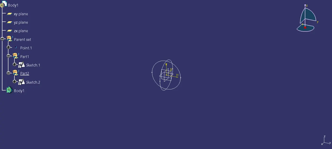
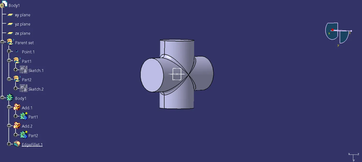
Tree structure for Body 1:
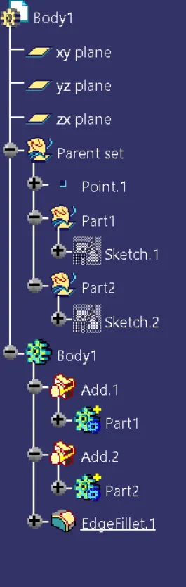
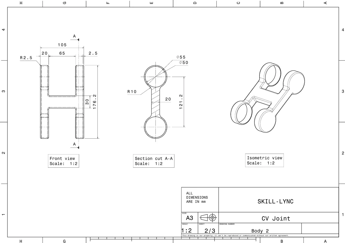
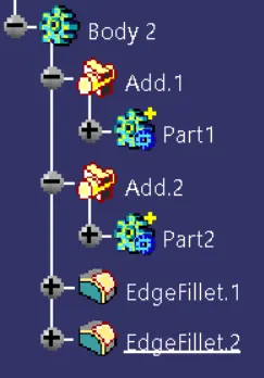
Body 2
- Side containing two circular profiles are created first as part 1 for body 2.
- A plane is created at an offset of 32.5mm from the XZ plane.
- Using this new plane as reference the profile is drawn.
- Surface is extruded using pad command to a thickness of 20mm.
- A new sketch is made on same plane with two circles at 121.2mm apart to make pockets.
- Pocket command is used to make hole at depth of 17.5mm in the previous body.
- The whole body is then mirrored along XZ plane to form the other side.
- A new rectangular sketch is made along the XZ plane with dimensions 30x20mm and extruded to both sides (65mm each).
- The two parts are merged using boolean addition to form body 2.
- Fillet command is used to give 2.5mm fillet all along the edges of the body and 10mm adjacent to circular profile.
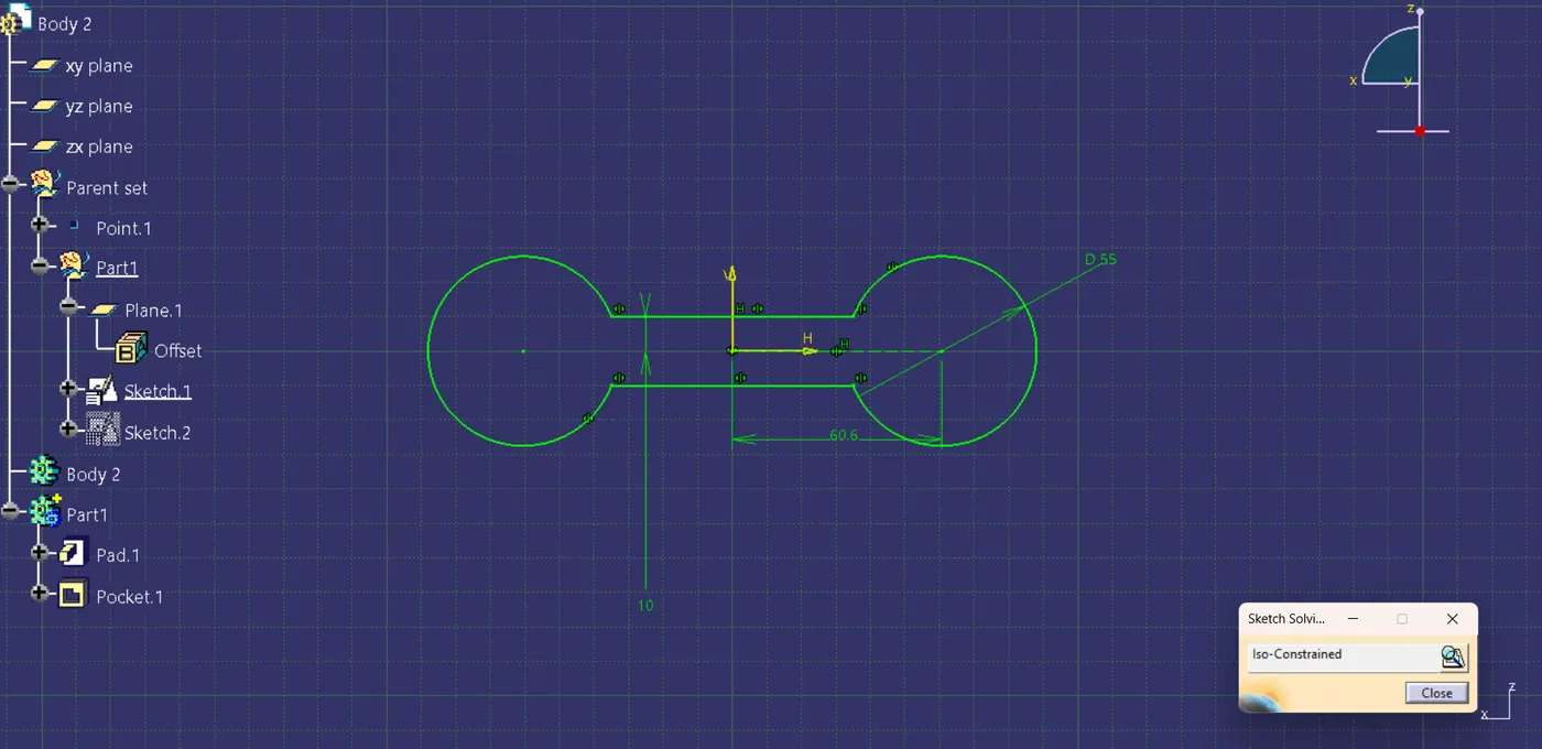
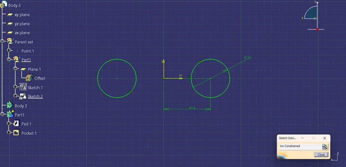
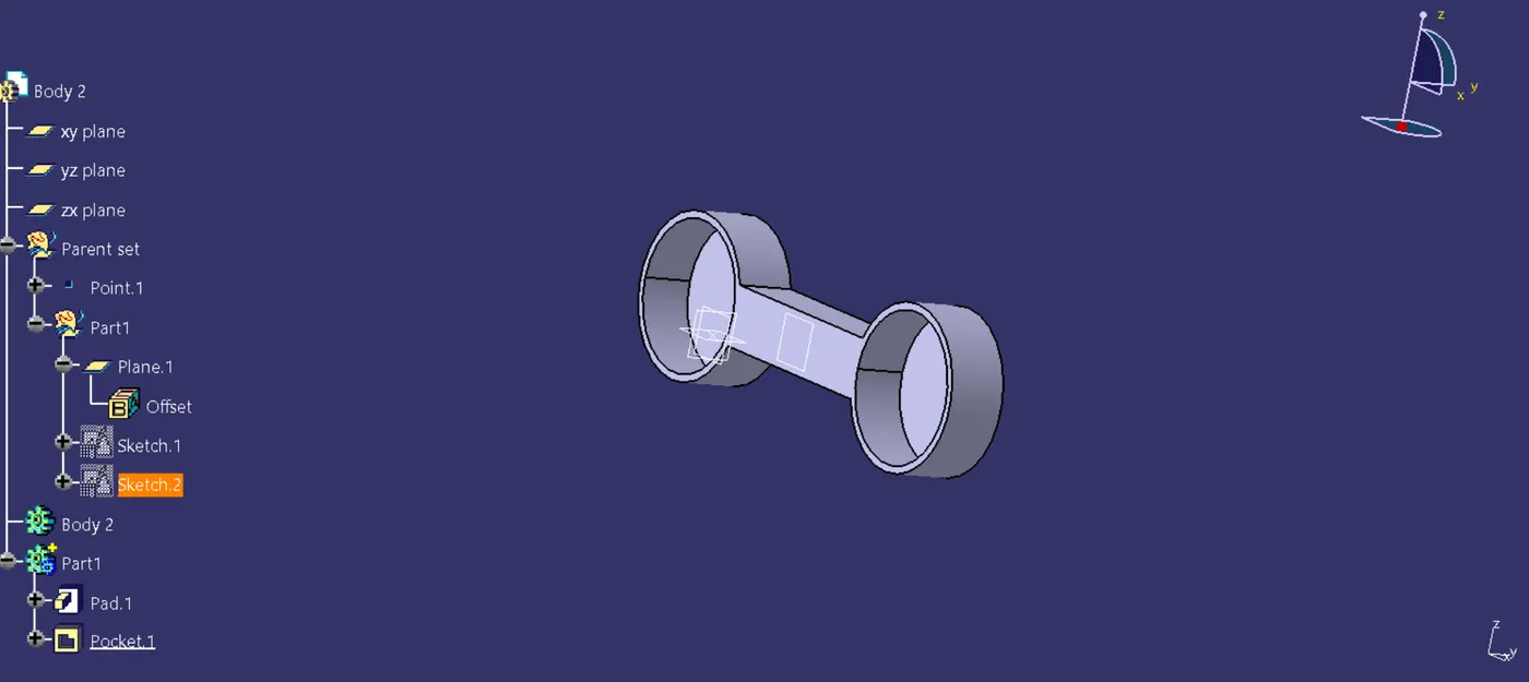
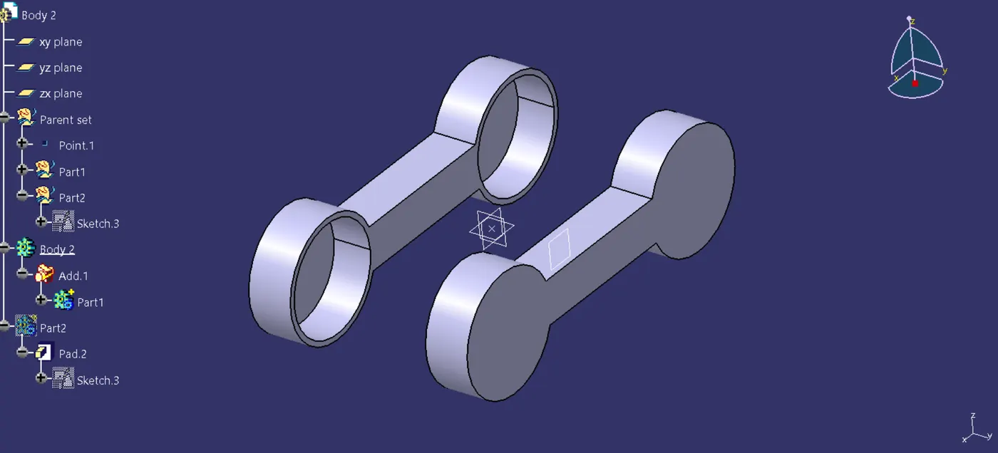
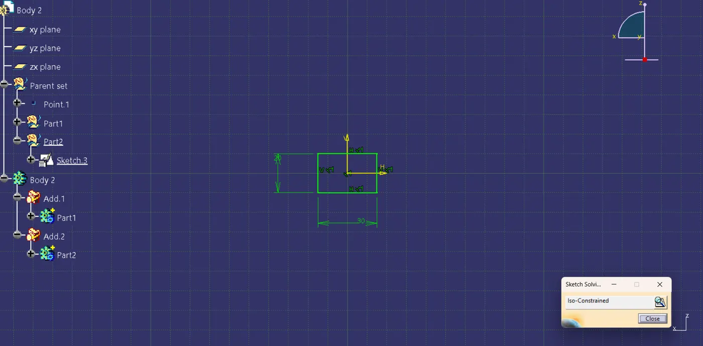
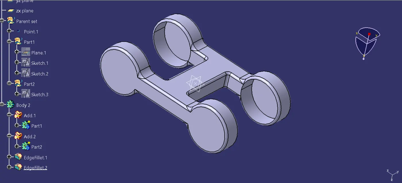
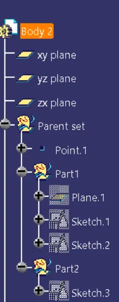
Tree structure for Body 2:
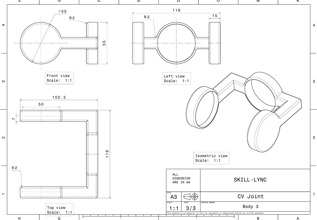
Body 3
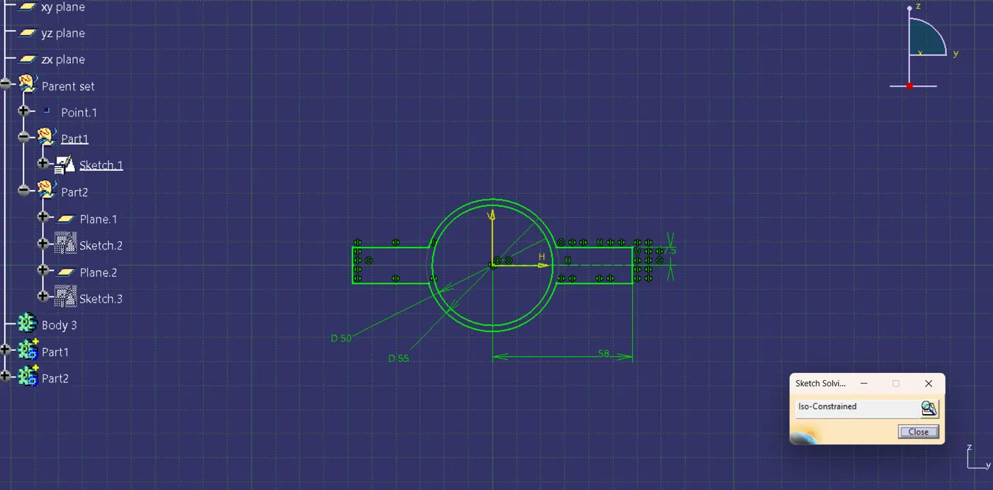
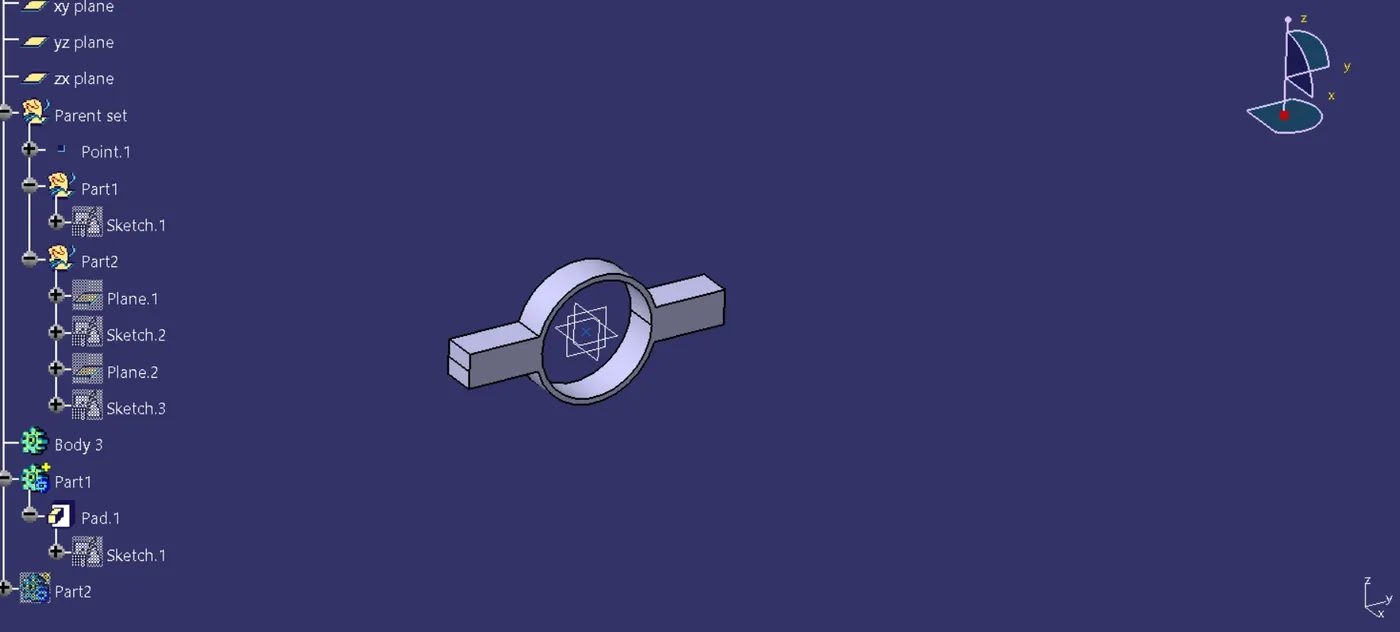
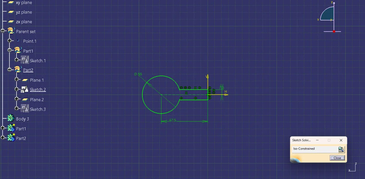
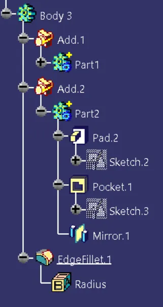
- Part containing center hole for axle is created first, with reference to YZ plane sketch is made according to dimensions and is extruded to 15mm using pad command.
- To create the mounts on side a new reference plane is created at an offset of 58mm from ZX plane.
- Sketch for the part is made on this plane and extruded inwards towards the center for 15mm.
- Another sketch is made for 50mm diameter which is used to pocket the geometry at a depth of 7mm.
- This geometry is mirrored along the central axis to form the other side of the component.
- Boolean addition is used to join the two parts together.
- Fillet of 2mm is given for all the edges.
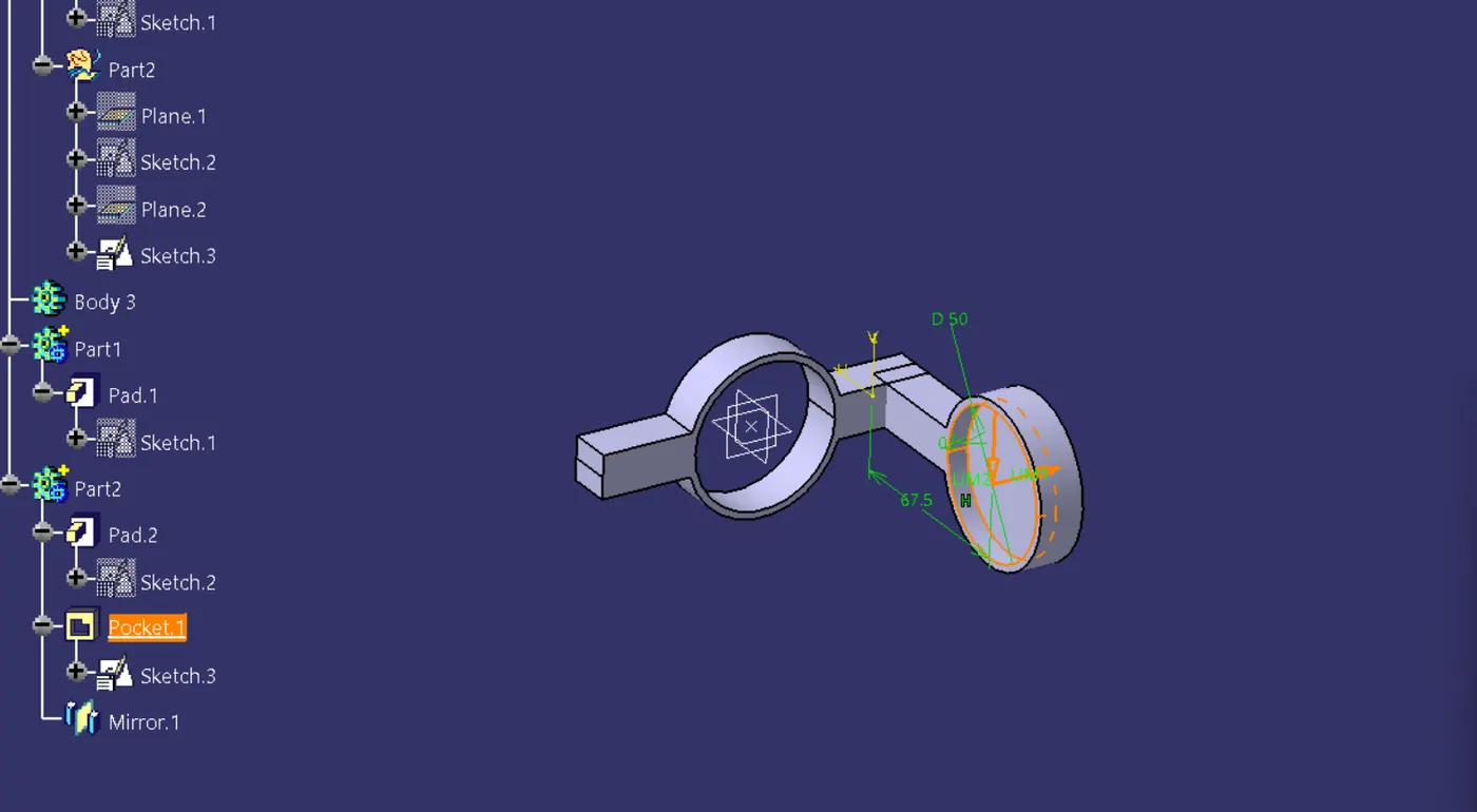
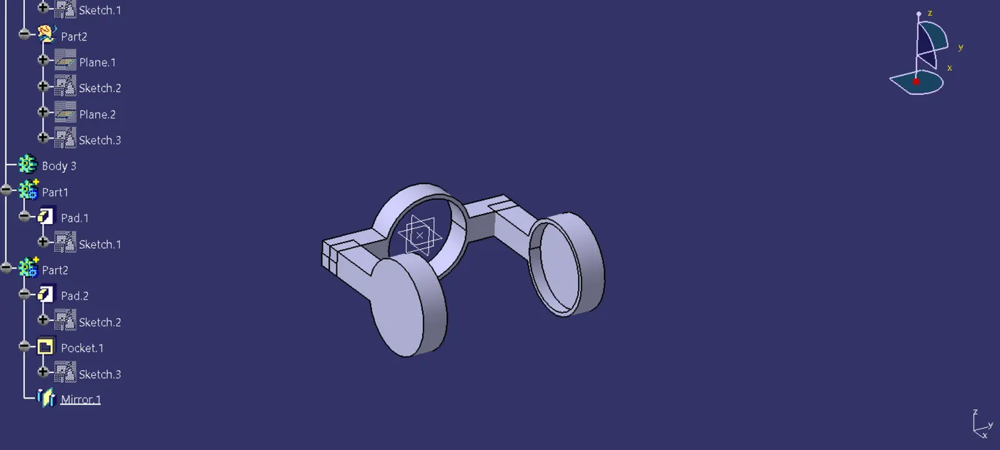
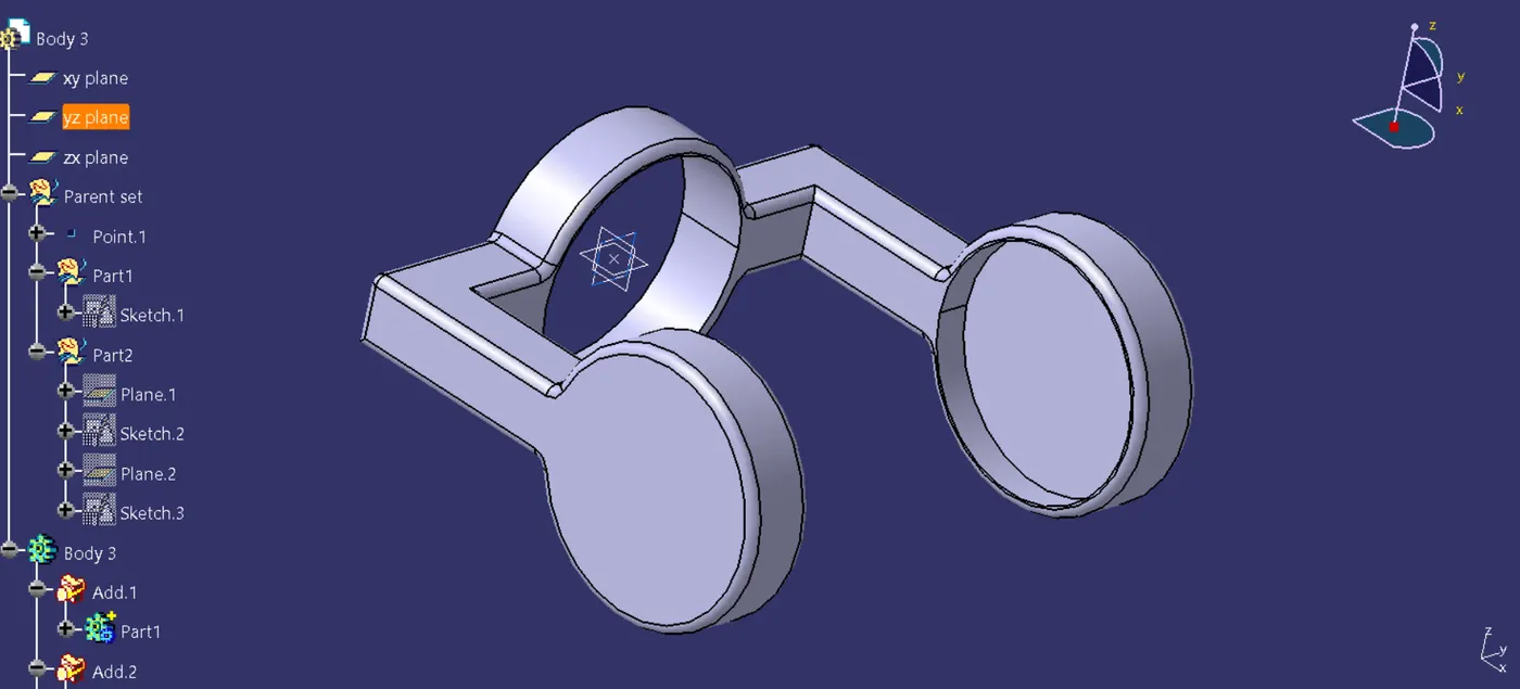
Tree structure for Body 3:
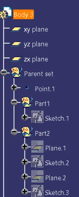
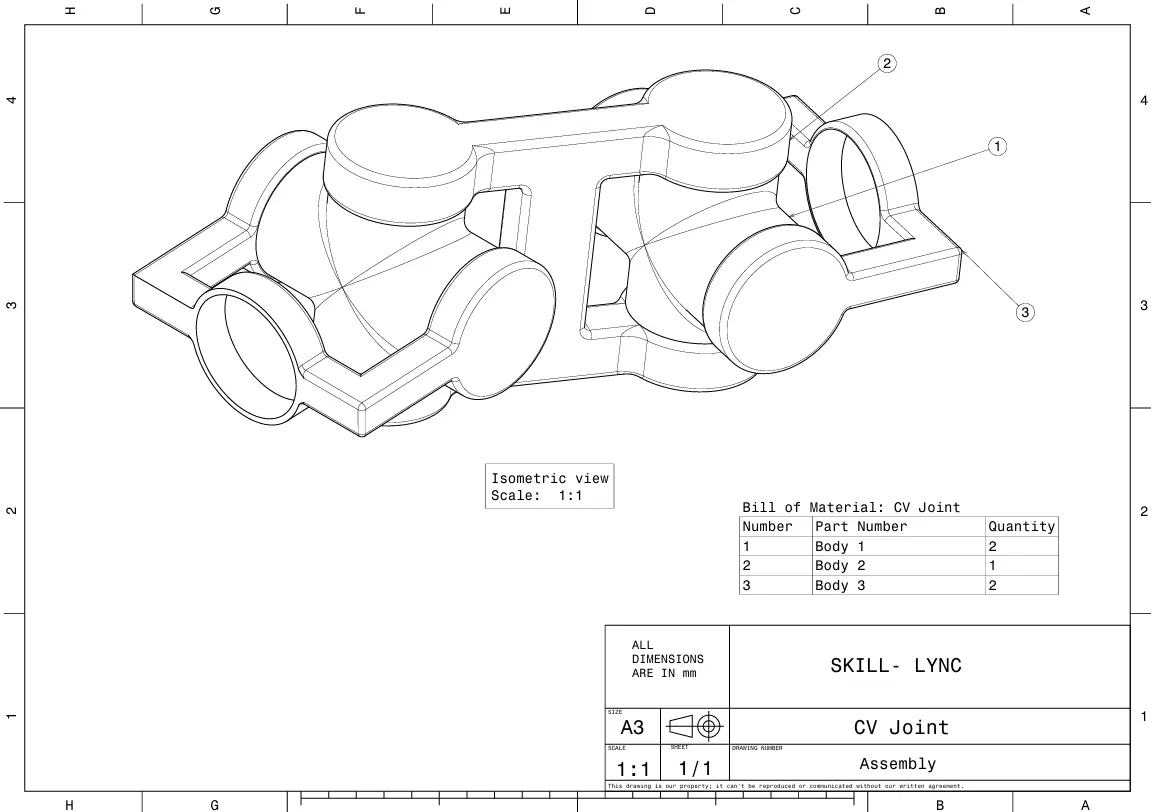
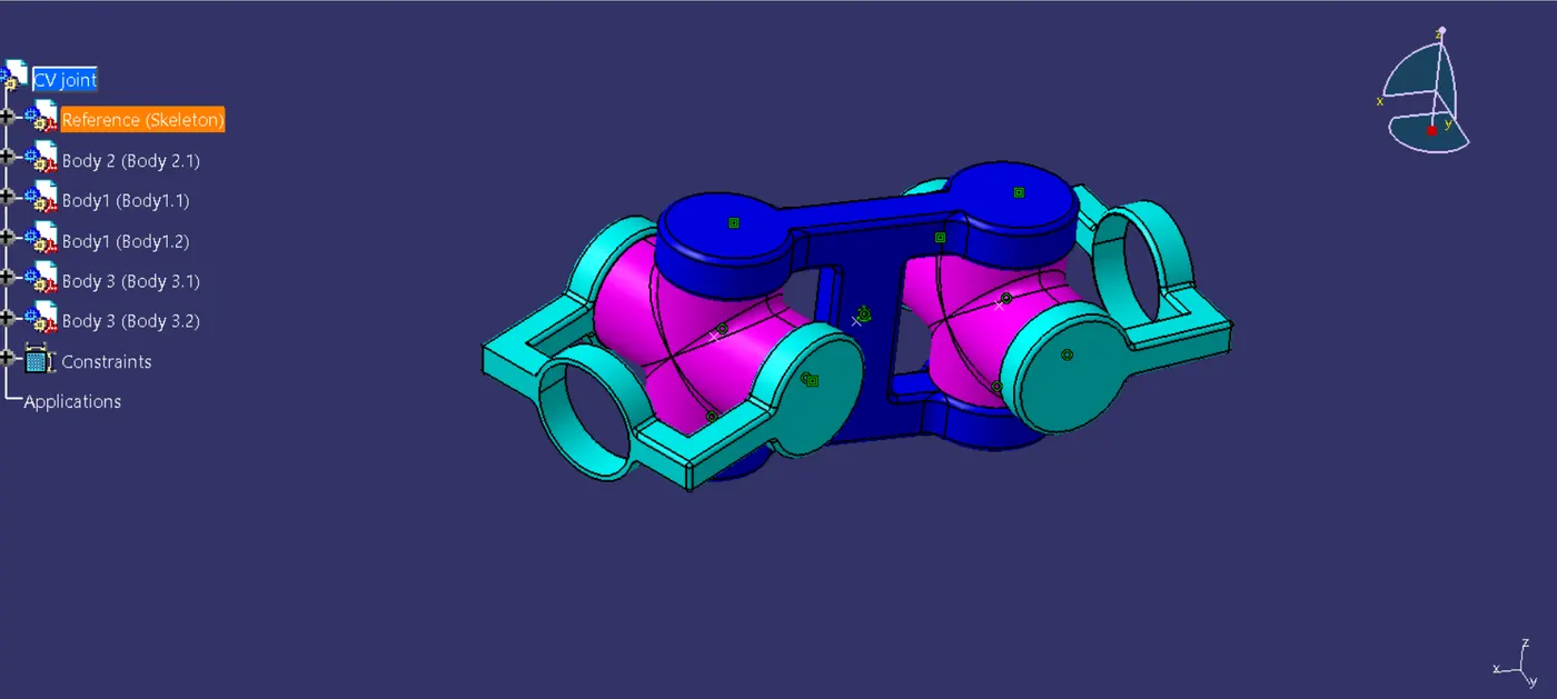
Assembly for CV joint
- New product file is opened for creating the assembly.
- New body is created inside the assembly file for reference/ skeleton for the whole assembly.
- The reference is fixed at origin with 3 planes and point at origin.
- Body 2 is imported first as it is going to occupy the center coinciding with reference set.
- After that body 1 and body 3 are imported, they are both made a copy as they are required twice.
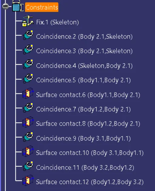
- All the bodies required for the assembly are given respective reference sets inside each of them. Reference axis created for circular mounts. These reference are used to provide constrains with others to complete the assembly.
- The created references are published.
- The bodies are roughly oriented in their positions using manipulation command.
- The published references are used to connect each other bodies with help of multiple constraints.
Drafting of the components