Week 7 Challenge - Assembly Workbench
Ans:
OBJECTIVE: This report aims to document the process of creating two assemblies, including the creation of individual part files and assembly workbench, using 2D diagrams. Additionally, this report will detail the use of drafting tools to create 2D drawings of those particular parts and assembled bodies as well.
INTRODUCTION:
ASSEMBLY WORKBENCH: Assembly Workbench in CATIA is a tool used for creating and managing assemblies of 3D models. It allows users to assemble various parts and components into a single product and simulate the assembly to check for fit, interference, and other design considerations. Assembly Workbench provides tools for managing assembly constraints, such as mating and aligning components, as well as tools for analyzing the assembly and its components. In CATIA, Assembly Workbench is an essential tool for creating complex mechanical products or systems.
PROCEDURE TO CREATE THESE BODIES AND ASSEMBLE THEM TOGETHER: In order to create the Quick Return Mechanism & the CV Joint, we need to assemble their respective individual parts. The 2D drawings provided in the challenge can be used to create these parts. Once the parts are created, they can be assembled to form complete bodies. This process involves carefully following the assembly instructions and ensuring that each part is correctly positioned and secured. As a professional, it is important to communicate clearly and concisely to colleagues or team members about the steps involved in the assembly process and to ensure that everyone understands the requirements and expectations for the project but since currently I am doing this entire process on my own hence I have to take all these things into consideration.
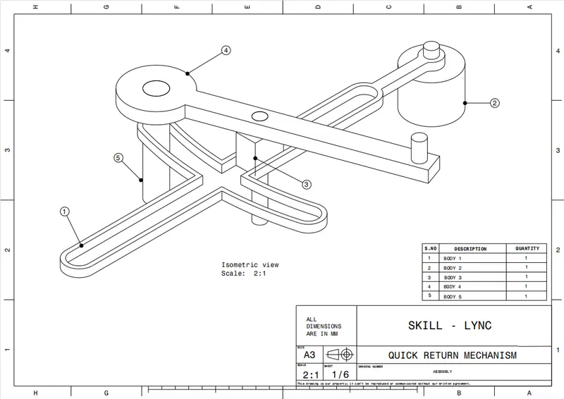
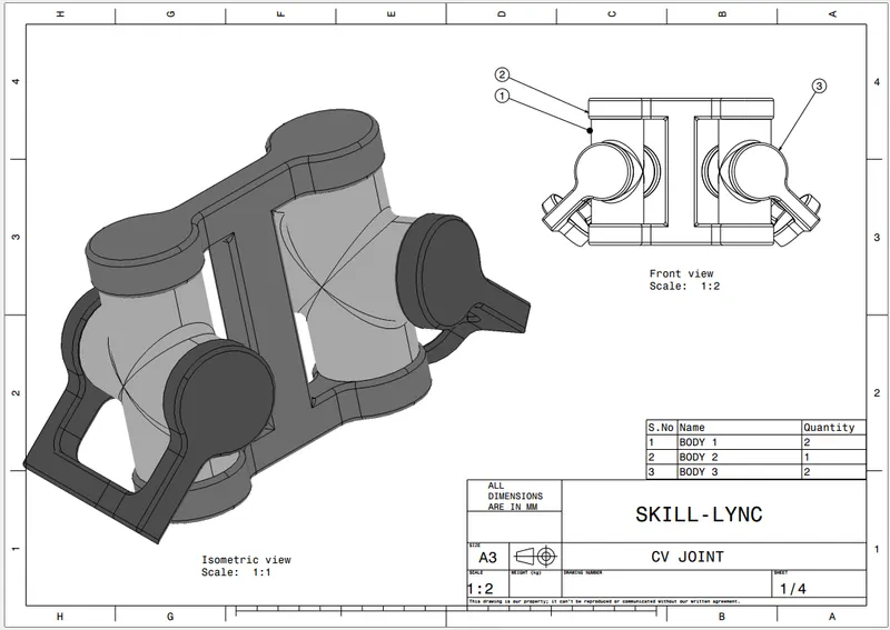
Here's how the Quick Return Mechanism and the CV Joint are supposed to look after assembling all of their respective parts together.
1. QUICK RETURN MECHANISM:
2. CV JOINT:
QUICK RETURN MECHANISM'S INDIVIDUAL PARTS MADE IN CATIA:
1. FIRST BODY:
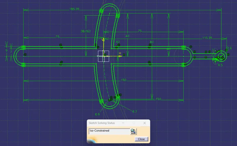
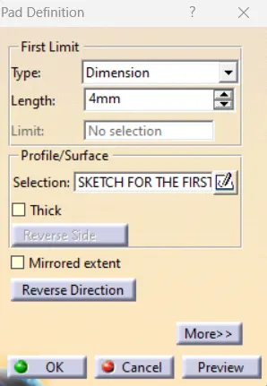
Now, we're going to create a solid body using the 'PAD' command as shown below:
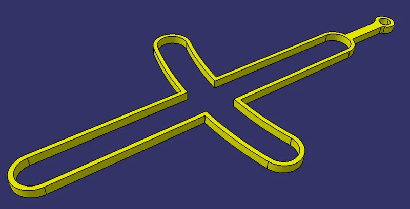
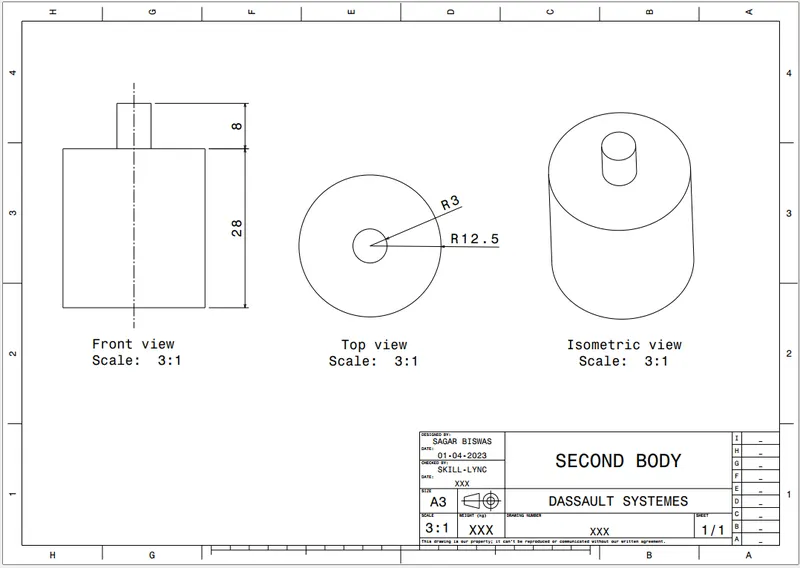
2. SECOND BODY:

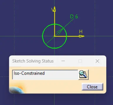
Again, we're going to create a solid body using the 'PAD' command as shown below:
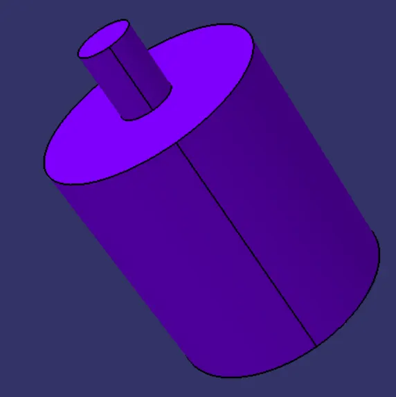
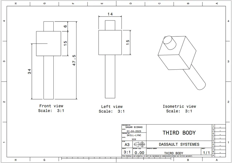
3. THIRD BODY:
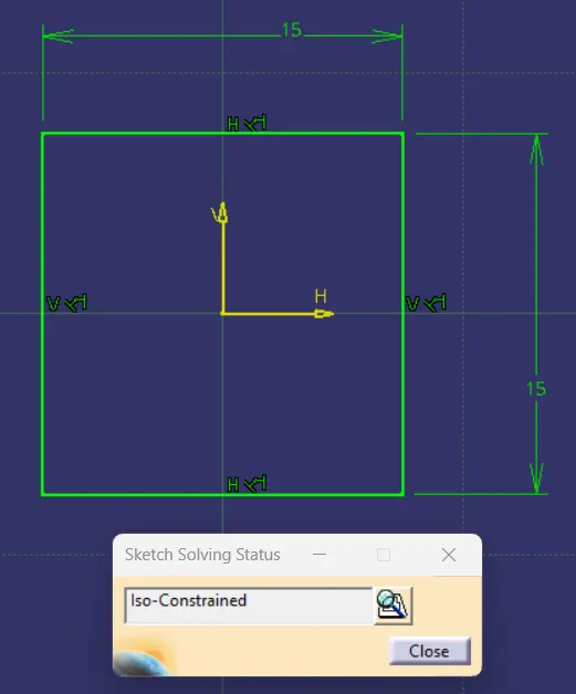
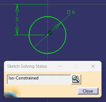
Using the PAD command, we have created the following body from the above sketches.
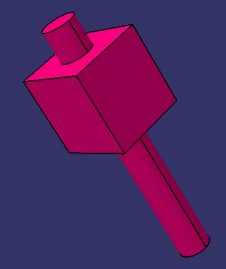
4. FOURTH BODY:
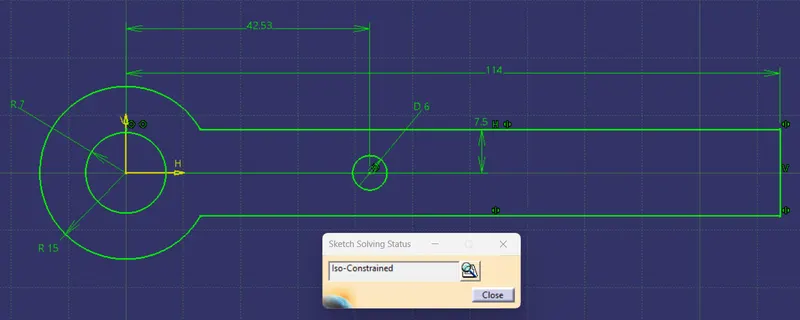
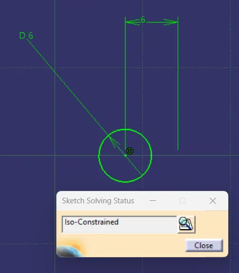
Using the PAD command, we have created the following body from the above sketches.
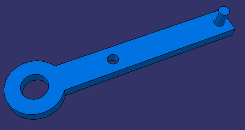
5. FIFTH BODY:
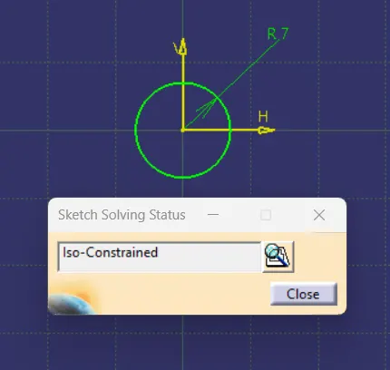
Using the PAD command, we have created the following body from the above sketches.
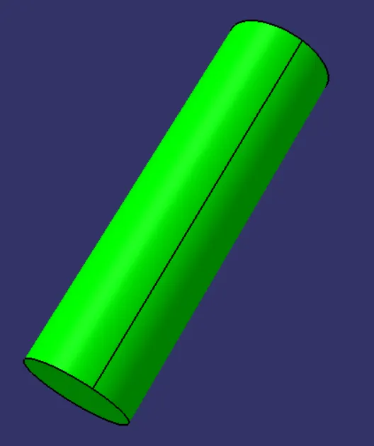
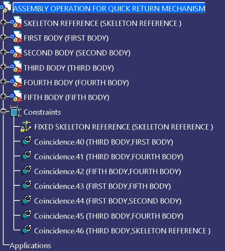
In CATIA's Assembly Workbench, the creation of a reference point, known as the Skeleton Reference, is a crucial step in designing an assembly. This point serves as the origin for assembling the various parts in relation to it. To ensure the proper positioning of parts, a reference point must also be created for each individual component.
To establish the Skeleton Reference, the 'Fix Component' command in the Constraint Toolbar is employed. This command allows for the anchoring of the Skeleton Reference point to a specific location. Once established, the individual parts can be connected to the Skeleton Reference point using the 'Constraint Toolbar' in the Assembly Workbench.
The Coincidence Constraint tool is a commonly used command in the Constraint Toolbar, which is employed to link the reference points of each individual part to the Skeleton Reference point. This ensures that the parts are assembled together in the correct orientation and position as required by the design.
In summary, creating a Skeleton Reference point and employing the Coincidence Constraint tool to connect individual parts to it is a critical process in CATIA's Assembly Workbench. The proper use of these tools ensures the accurate modelling, testing, and analysis of assemblies, resulting in a final product that meets the desired specifications.
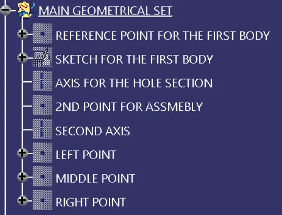
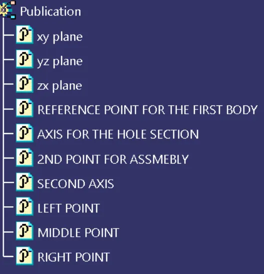
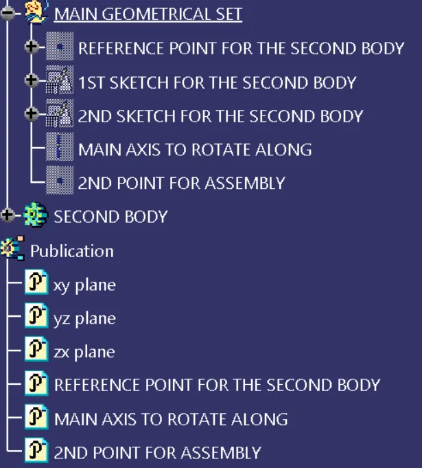
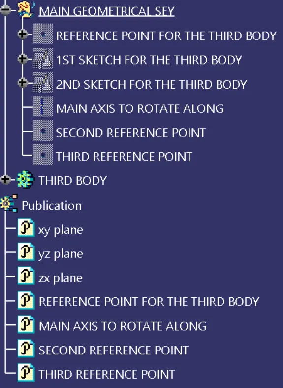
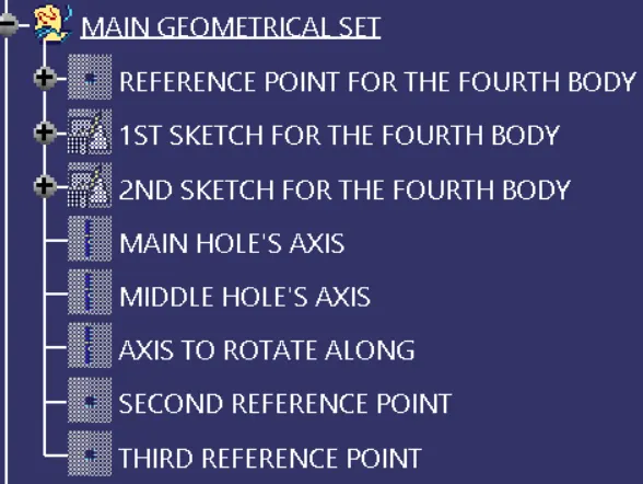
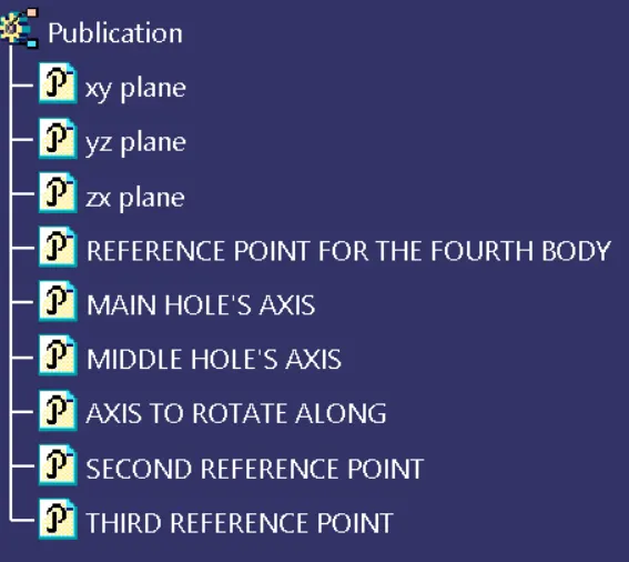
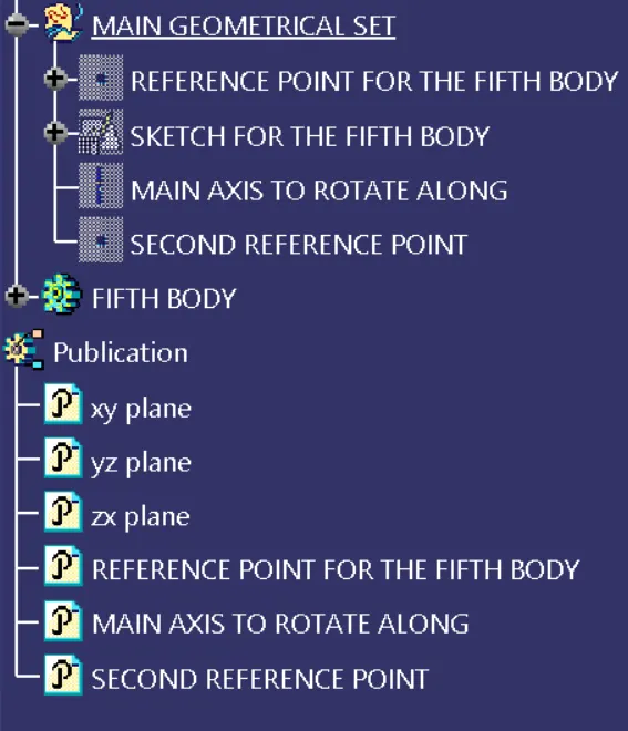
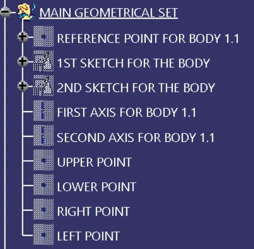
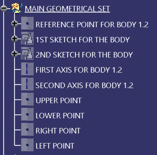
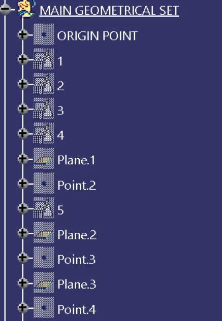
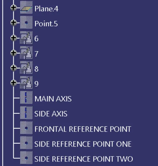
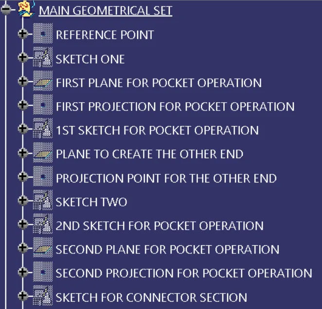
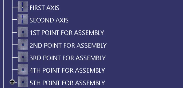
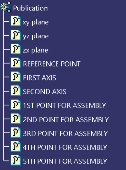
Various points and axes are made for each body so that it can be assembled with respect to the skeleton reference point.
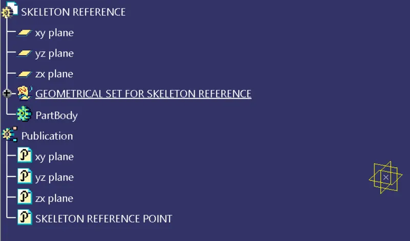
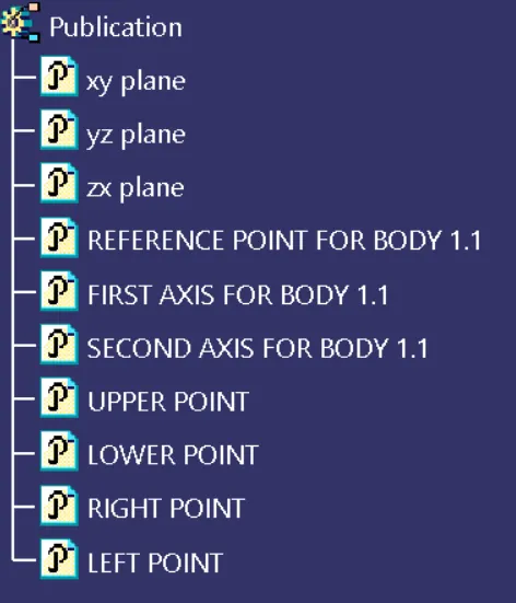
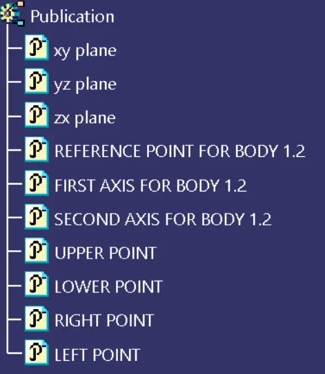
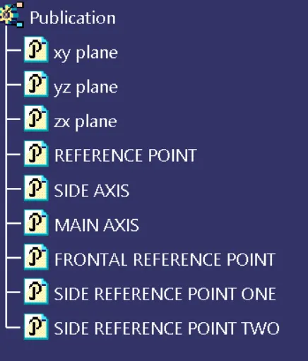
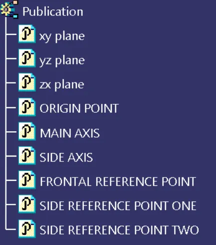
We also have to publish all these points along the planes as shown below:
SKELETON REFERENCE POINT FOR QUICK RETURN MECHANISM:
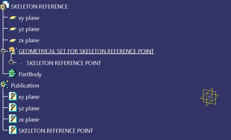
1. POINTS & AXES FOR THE FIRST BODY:
2. POINTS & AXES FOR THE SECOND BODY:
3. POINTS & AXES FOR THE THIRD BODY:
4. POINTS & AXES FOR THE FOURTH BODY:
5. POINTS & AXES FOR THE FIFTH BODY:
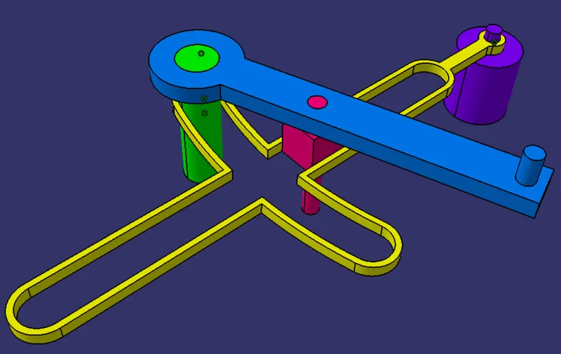
QUICK RETURN MECHANISM'S PARTS ASSEMBLED TOGETHER:
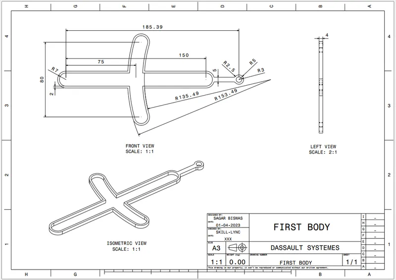
DRAFTING WORKBENCH FOR QUICK RETURN MECHANISM:
1. FIRST BODY:
2. SECOND BODY:
3. THIRD BODY:
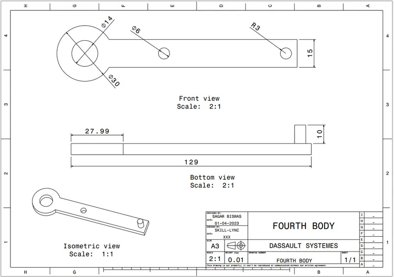
4. FOURTH BODY:
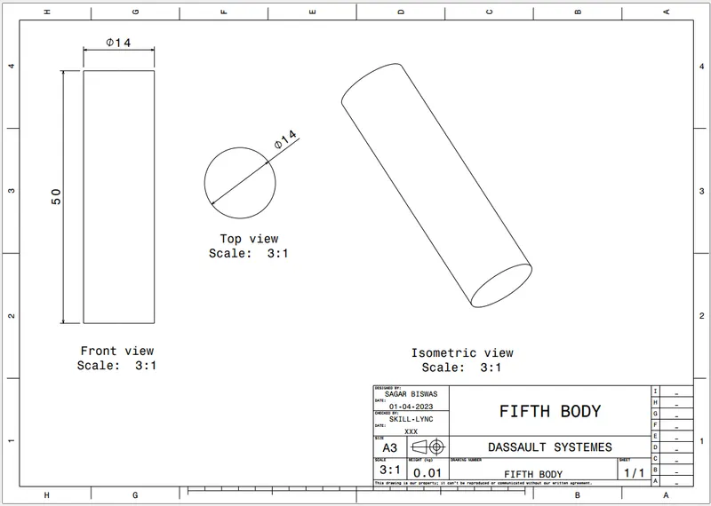
5. FIFTH BODY:
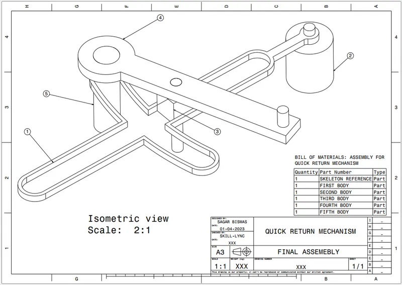
6. ALL COMPONENTS OF THE QUICK RETURN MECHANISM ASSEMBLED TOGETHER:
IN THE SHEET BACKGROUND: 1. FRAME & TITLE BLOCK 2. BILL OF MATERIALS
CV JOINT'S INDIVIDUAL PARTS MADE IN CATIA:
1. FIRST BODY:
A. Sketch along the First Axis:
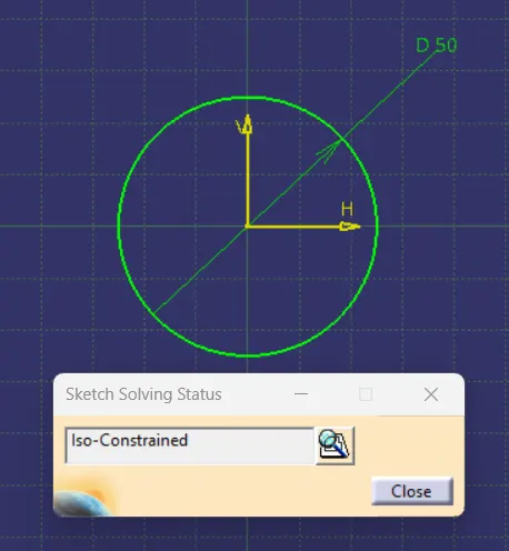
B. Sketch along the Second Axis:
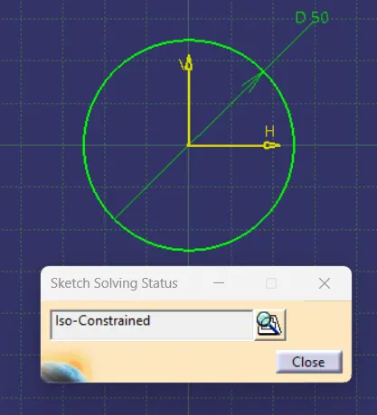
Using the PAD command, we have created the following body from the above sketches.
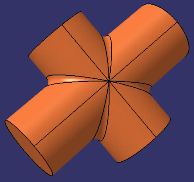
2. SECOND BODY:
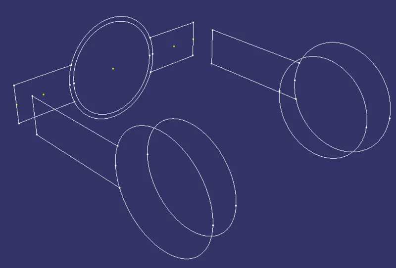
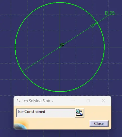
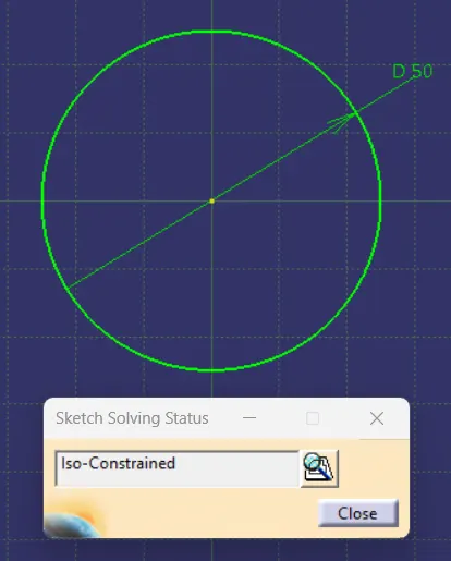
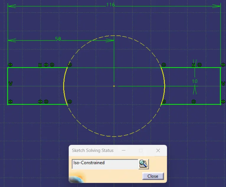
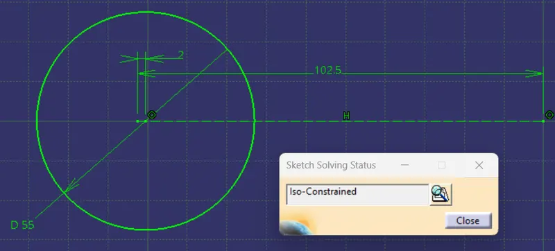
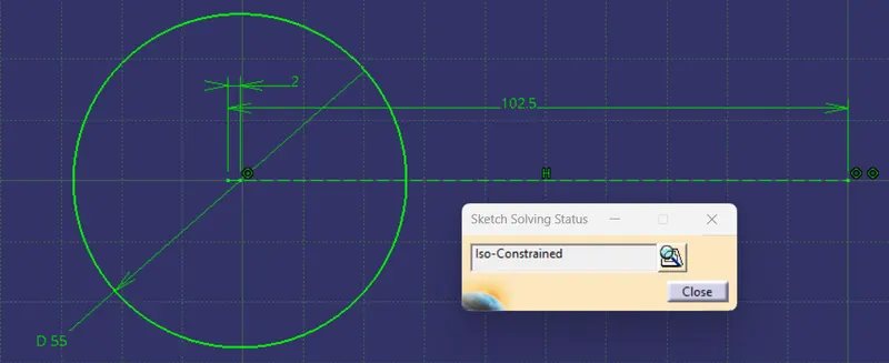
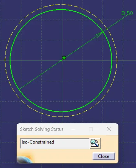
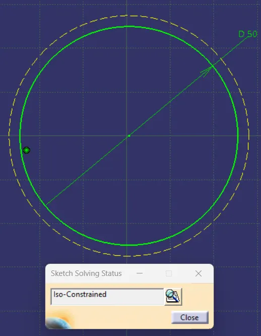
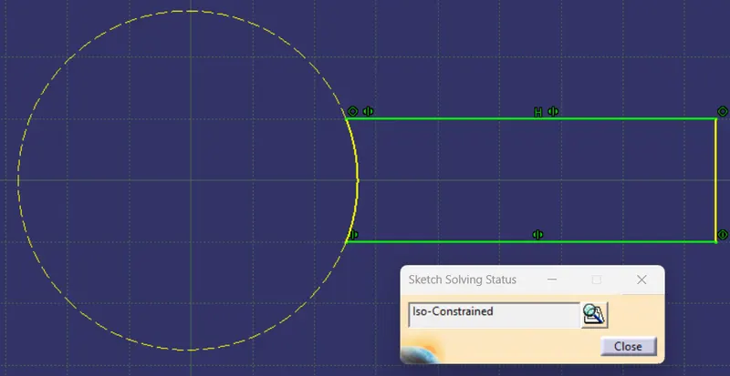
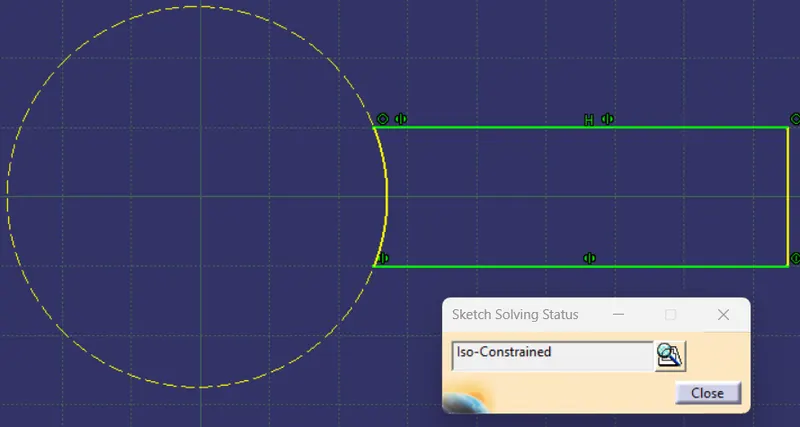
Using the PAD command, we have created the following body from the above sketches.
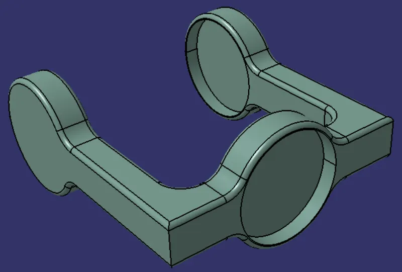
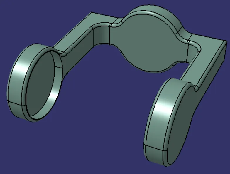
3. THIRD BODY:
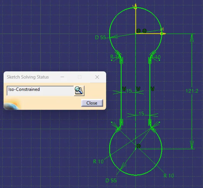
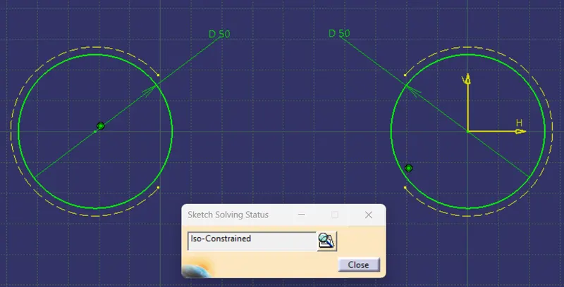
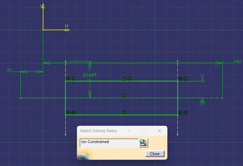
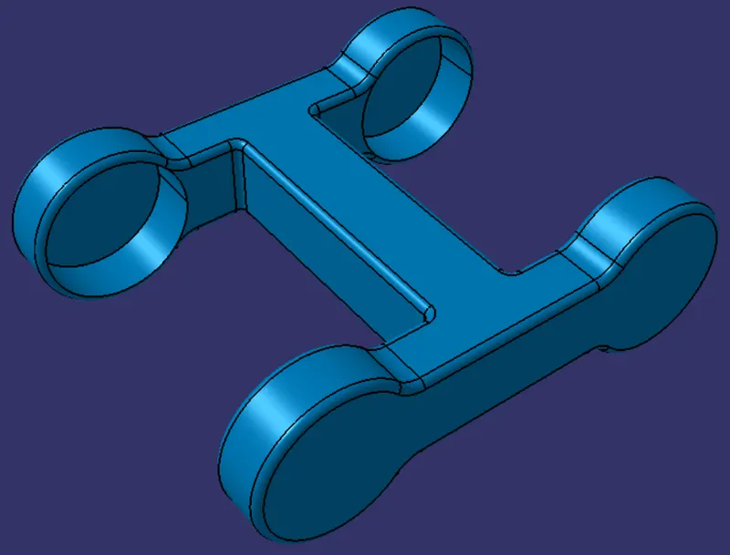
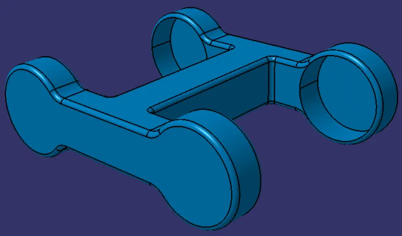
Using the PAD command, we have created the following body from the above sketches.
SKELETON REFERENCE POINT FOR CV JOINT:
1. POINTS & AXES FOR THE FIRST BODY:
2. POINTS & AXES FOR THE SECOND BODY:
3. POINTS & AXES FOR THE THIRD BODY:
4. POINT & AXES FOR THE FOURTH BODY:
5. POINT & AXES FOR THE FIFTH BODY:
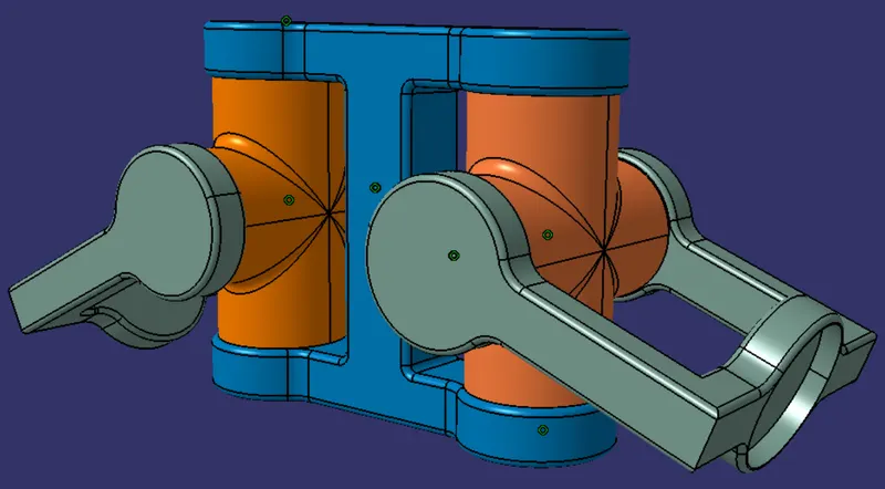
CV JOINT'S PARTS ASSEMBLED TOGETHER:
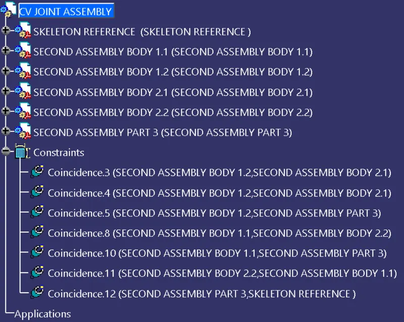
DRAFTING WORKBENCH FOR THE CV JOINT:
1. FIRST BODY:
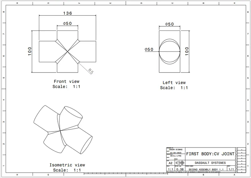
2. SECOND BODY:
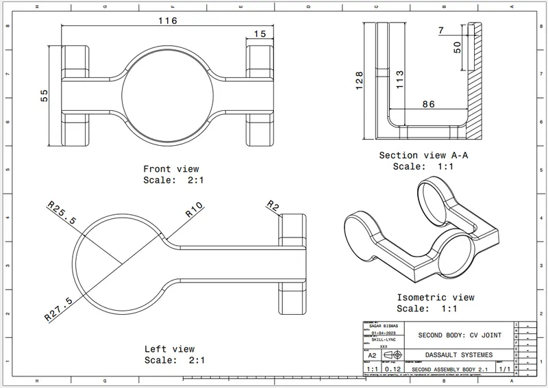
3. THIRD BODY:
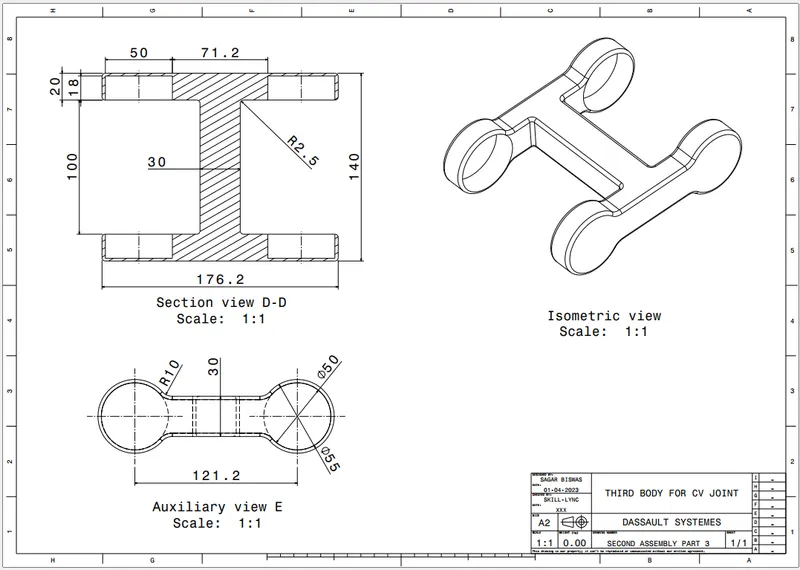
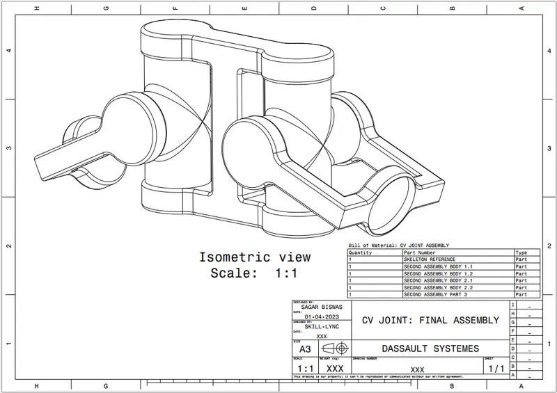
4. ALL COMPONENTS OF THE CV JOINT ASSEMBLED TOGETHER:
IN THE SHEET BACKGROUND: 1. FRAME & TITLE BLOCK 2. BILL OF MATERIALS
To summarize my report:
The CATIA V5 software was used to design two products: a Quick Return Mechanism and a CV Joint.
The design process involved creating 2D sketches in the Sketcher Workbench for individual bodies which were then converted into solid bodies using the Part Workbench. The Assembly Workbench was utilized to assemble these bodies with respect to a Skeleton Reference Point, resulting in the creation of the two products. The Drafting Workbench was then used to create detailed drawings for each part. These steps were documented in detail in the report and also the files in the .CATPart and .CATProduct is attached to this report.