Project 1
Ans: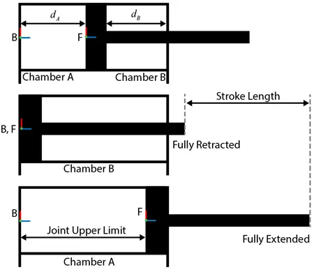
Double Acting Hydraulic Actuator System:
Double-acting hydraulic cylinder Double-acting hydraulic cylinders are linear hydraulic actuators that perform the movement in both directions using hydraulic pressure. The piston stroke in double-acting cylinders is much longer than in a single-acting cylinder.
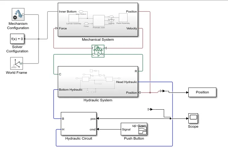
This figure shows the block diagram of the double-acting cylinder model described above. The example uses two Translational Mechanical Converter (IL). blocks to model the chambers A and B of the cylinder. A Translational Multibody Interface block connects the Translational Mechanical Converter (IL) blocks to the Prismatic Joint block. See Connecting Simscape Networks to Simscape Multibody Joints for details of how to use the Translational Multibody Interface block.
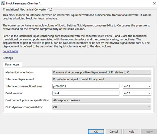
In chamber A, a tension at port A maneuvers the cylinder from 0 to stroke length. The dislodging of the cylinder equivalents to the position result of the Prismatic Joint block. To show chamber A:
Associate the ports C and R of the Translational Multibody Interface block to the ports C and R of the upper Translational Mechanical Converter (IL) block, individually.
In the Translational Mechanical Converter (IL) block, set Interface removal to Provide input signal from Multibody joint to empower port p.
Interface ports p of the Prismatic Joint block and Translational Mechanical Converter (IL) block.
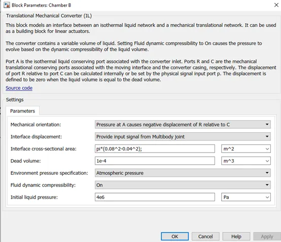
In chamber B, the strain at port A maneuvers the cylinder from 0 to negative stroke length. Subsequently, you really want to change the default direction and add an offset to the information position sign of the lower Translational Mechanical Converter (IL) block. The offset approaches - dB.
In the lower Translational Mechanical Converter (IL) block, set Mechanical direction to Pressure at A makes negative dislodging of R relative C.
Set Interface uprooting to Provide input signal from Multibody joint to empower the port p.
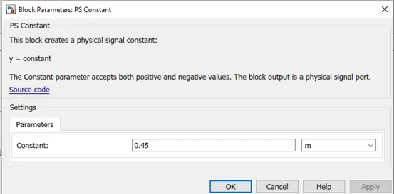
Add a PS Constant block and indicate the steady as the stroke length of the chamber.
Add a PS Subtract block, then associate it to the PS Constant and Prismatic Joint blocks as displayed in the graph. Note that the result of the PS Subtract block rises to - dB.
To restrict the movement of the cylinder:
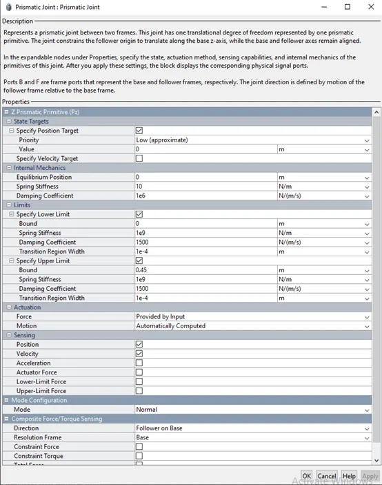
In the Prismatic Joint block, under the Limits segment, select the Specify Lower Limit and Specify Upper Limit boundaries.
Under the Specify Lower Limit area, the Bound boundary shows the base distance between the edges B and F of the joint block. In this model, determine the Bound boundary as 0 m.
Under Specify Upper Limit, the Bound boundary shows the greatest distance between outlines B and F of the Prismatic Joint block. In this model, determine the Bound boundary as the stroke length of the chamber.
Twofold acting chamber frameworks can be utilized in numerous applications. For instance, a dump trailer can utilize a twofold acting chamber to incite a scissor lift instrument that raises and brings down the landfill bed. See Hydraulic Interface - Dump Trailer with Hydraulic Cylinder (Simscape Multibody) for additional subtleties. Under the cover of the Double-Acting Hydraulic Cylinder block in the scissor raise are the mechanical and water driven subsystems, which are associated by a Translational Multibody Interface block. The Prismatic Joint block in the mechanical subsystem gives the position data to the two actuators in the pressure driven subsystem, Head Chamber and Bottom Chamber, that have the contrary settings of the Mechanical direction boundary. The Constant block C gives a position signal offset to the Head Chamber actuator, since when the Bottom Chamber is at dead volume (where position p = 0), the Head Chamber is at most extreme stroke.
Mechanical System

1)Cylinder Assembly
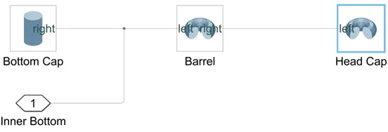
2) Bottom Cap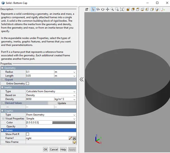
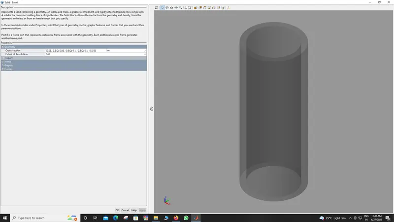
3) Barrel Cap
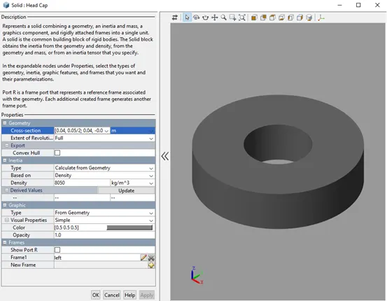
4) Head Cap
5) Prismatic Joint
6)Piston Assembly
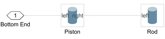
7)Piston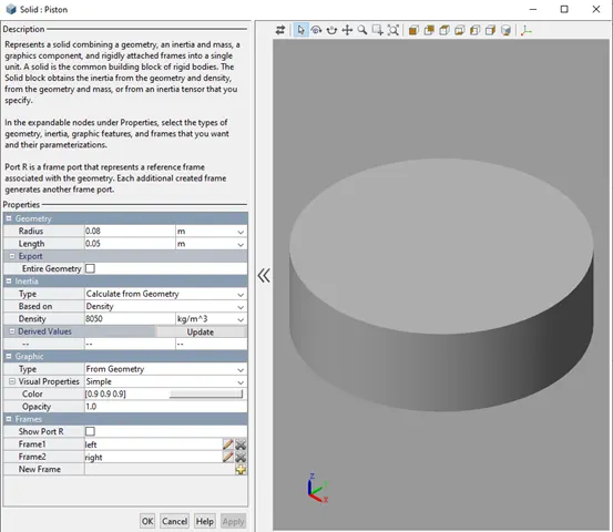
8) Rod
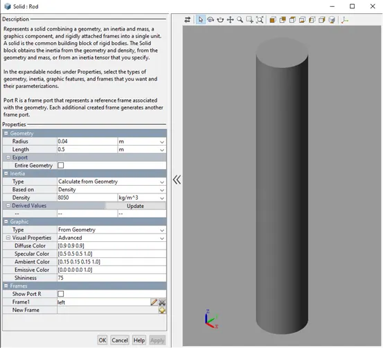
Hydraulic System
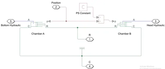
Chamber A:
Chamber B:
C:
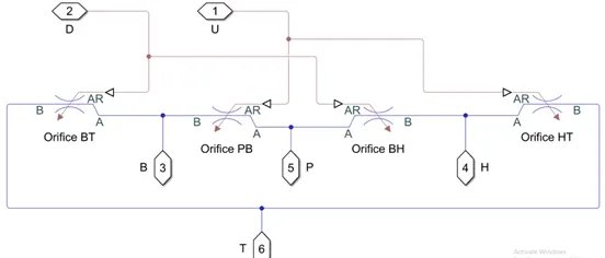
Hydraulics:
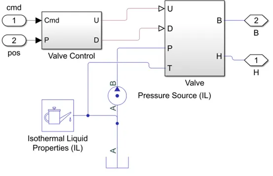
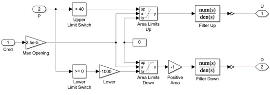
Valve Control:
Valve:
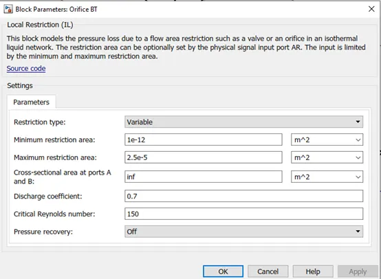
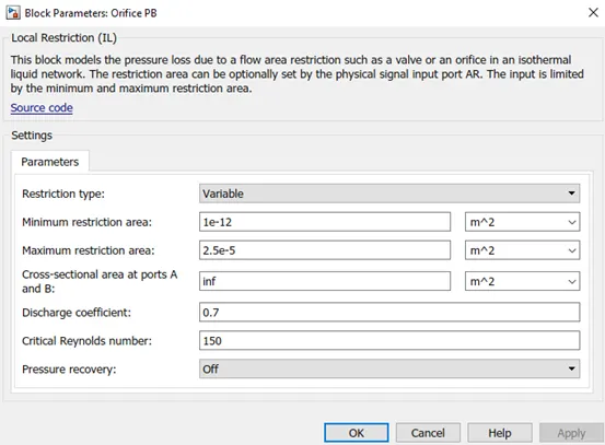
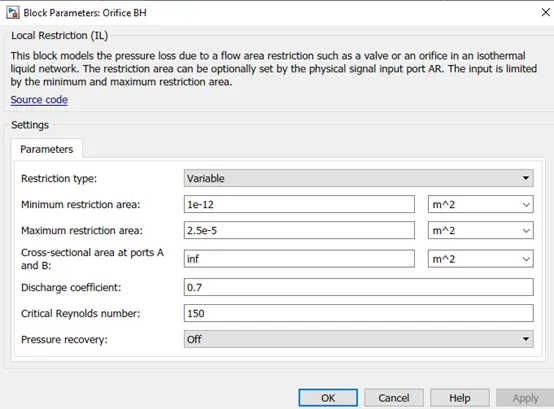
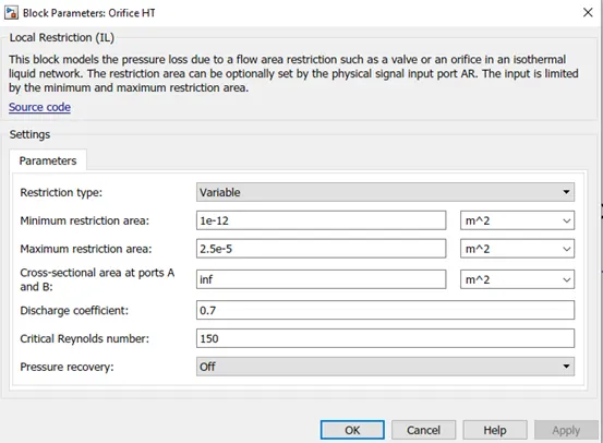
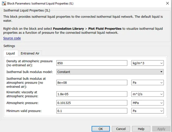
Iso thermal liquid properties:
isothermal liquid domain, the working fluid is a mixture of liquid and a small amount of entrained air. Entrained air is the relative amount of non-dissolved gas trapped in the fluid. You can control the liquid and air properties separately: You can specify zero amount of entrained air.
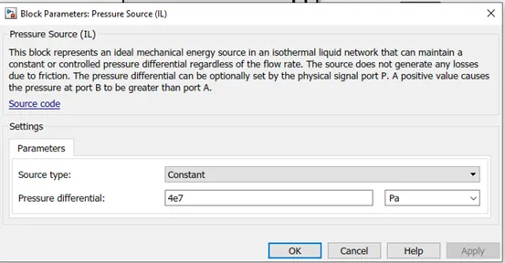
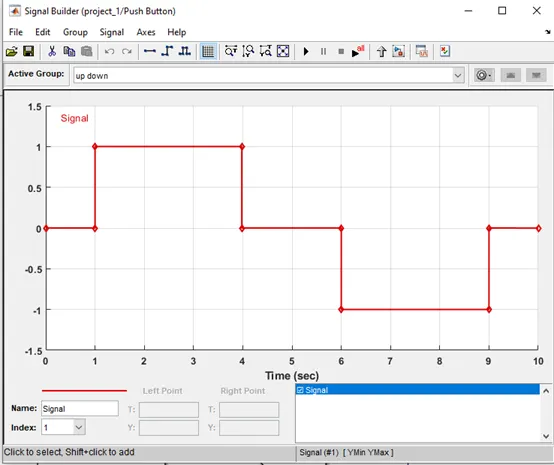
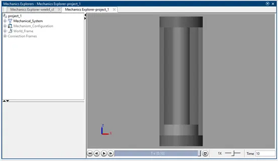
Result: The animation of the acutuator can be observed while running the Simulink file attached below.