Week 7 Challenge - Assembly Workbench
Title- Assembly Workbench
Aim-
To create assembly for Quick return mechanism and CV Joint.
Objectives:-
- To create the individual part files according to 2D diagrams of the components are provided.
- To create a complete assembly of those part files in the assembly workbench
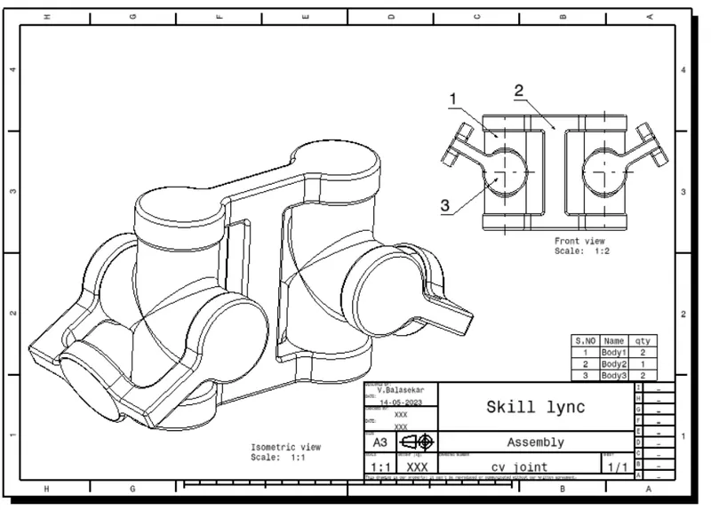
- To create the 2D drawing of parts and assembly using drafting workbench.
Workbech Required-
- Part Modelling
- Assembly
- Drafting
Methodology-
- Part Modelling- Create a solid part model using given input dimensions
- Assembly-
- Assembly modeling is the process of creating designs that consist of two or more components assembled together at their respective work positions.
- The components are brought together and assembled in Assembly Design workbench by applying suitable parametric assembly constraints to them.
- The assembly constraints allow you to restrict the degrees of freedom of components on their respective work positions.
- The assembly files in CATIA are called Product files. There are two methods to invoke the Assembly Design workbench of CATIA.
- The primary method to start a new product file is by selecting File > New from the menu bar to open the New dialog box From this dialog box select Product, as shown in Figure 11-1. The other method of invoking the Assembly Design workbench is by choosing Start > Mechanical
- Design > Assembly Design from the menu bar.
Types of Assembly Design Approach:-
In CATIA you can create assembly models by adopting two types of approaches. The first design approach is the bottom-up approach, and the second one is the top-down approach. Both these design approaches are discussed below
- Bottom-up Assembly
The bottom-up assembly is the most preferred approach for creating assembly models. In this of approach, the components are created in the Part Design workbench as (*.CATPart) file. Then the product (*.CATProduct) file is started and all the previously created components are inserted and placed in it using the tools provided in the Assembly Design workbench.
After inserting each component, constraints are applied to position them properly in the 3D space with respect to other components
- Top-down Assembly
In the top-down assembly design approach, components are created inside the Assembly Design workbench. Therefore, there is no need to create separate part files of the components. This design approach is completely different from the bottom-up design approach. Here you have to start the product file first and then, one by one, create all components. Note that even though the components are created inside the product file, they are saved as individual part files and can be opened separately later.
- Drafting- Create drawing of assembly and part individually.
Body 1
Sketch workbench
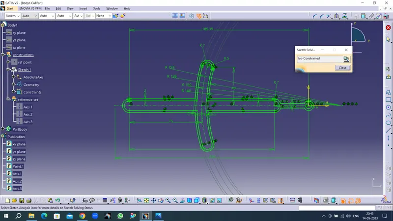
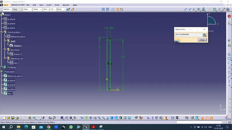
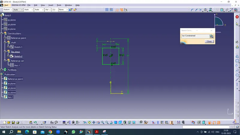
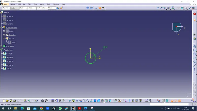
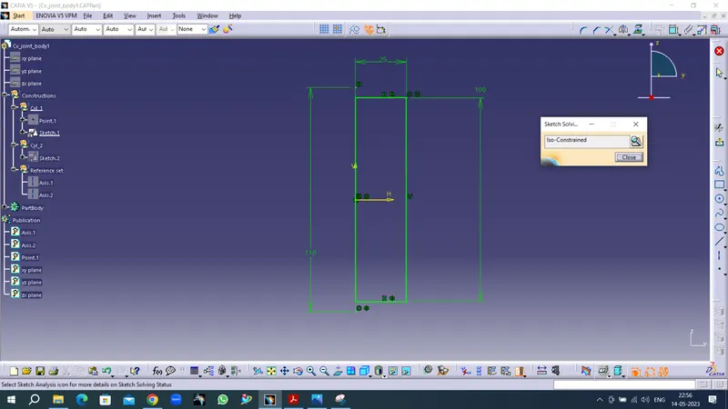
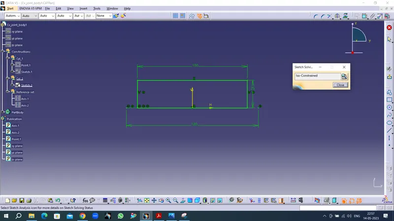
- Started the sketch workbench with positioned sketch with reference point .
- COnstructed all geometry and constraints in Geomentrical set.
- After completion of sketch checked the sketch solving status with Iso-constrained.
Part workbench
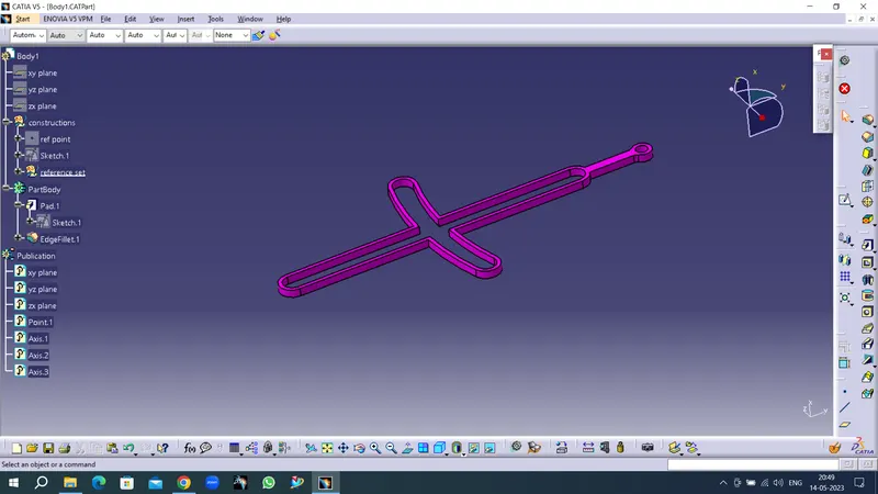
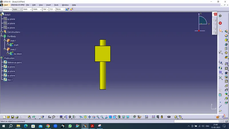
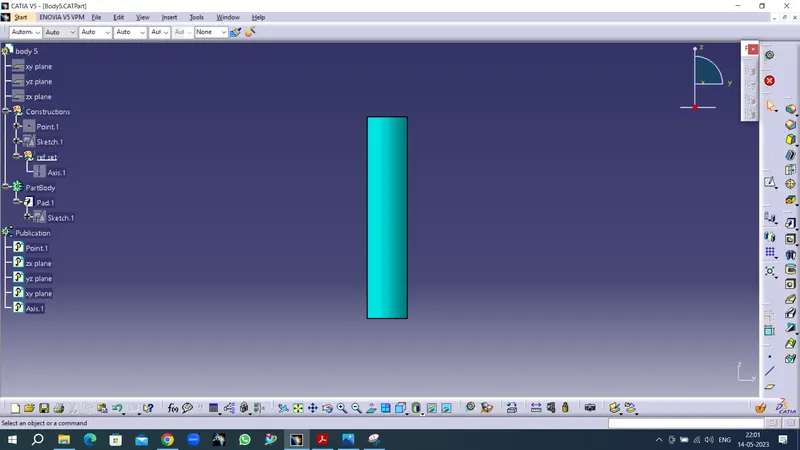
After exit workbench created part body with the pad command.If it is a multiple geometry create separate Body and apply boolean operations under the main part body.
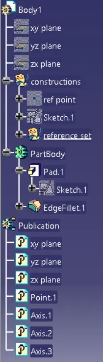
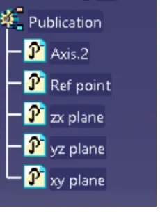
Publication
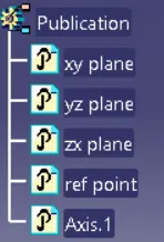
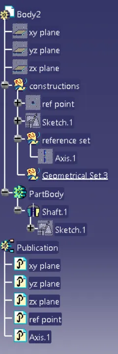
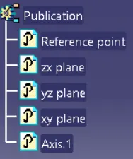
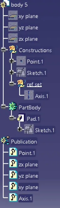
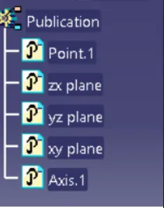
In assembly workbench, during Contextual Design, Publication option becomes very useful.
One can publish a plane, a sketch or a parameter which is not readily visible in the specification tree.
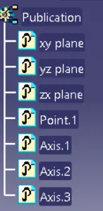
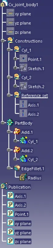
Specification tree
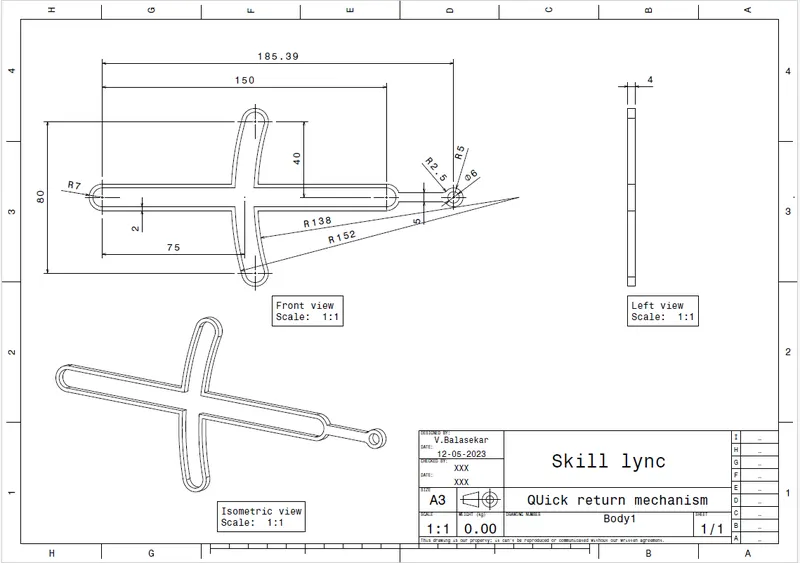
2d drawing of Body1
Body 2
Sketch workbench
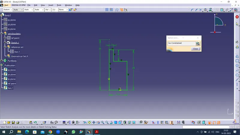
Part Workbench
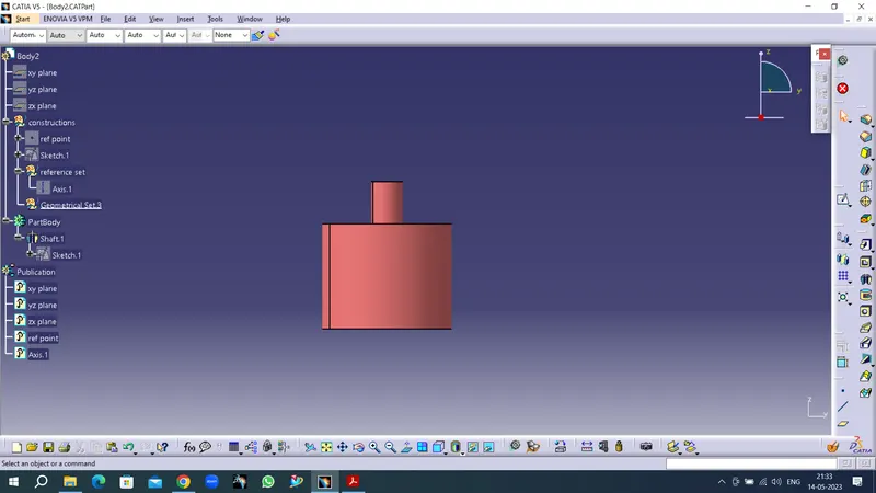
Specification tree & Publication
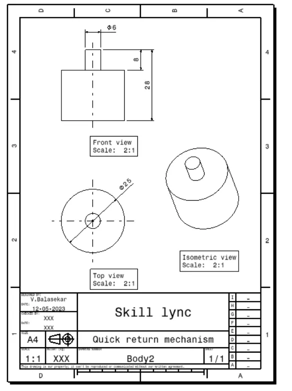
2d drawing
Body3
Sketch workbench
Part Workbench
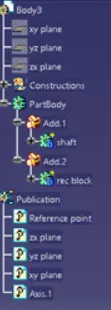
Specification tree & Publication
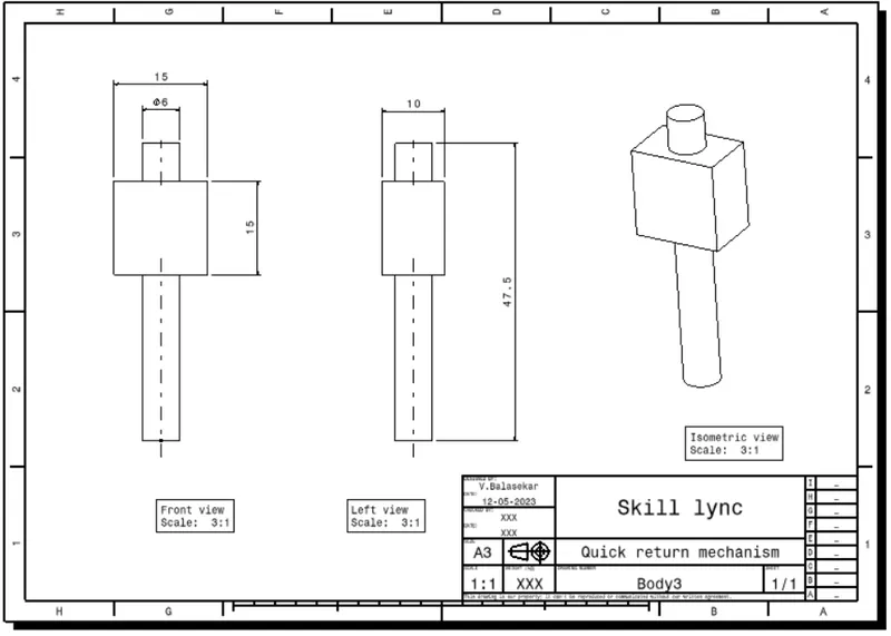
2d drawing
Body4
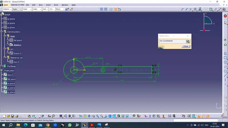
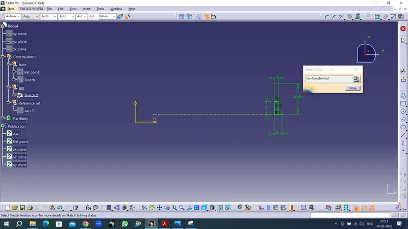
Sketch workbench
Part Workbench
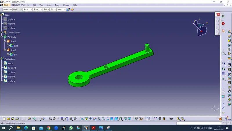
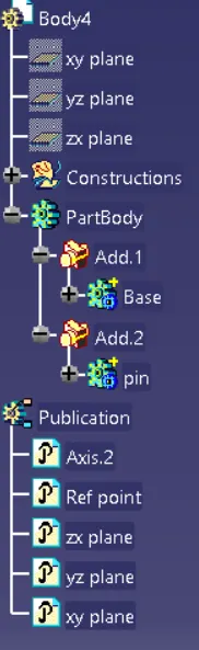
SPecification tree & Publication
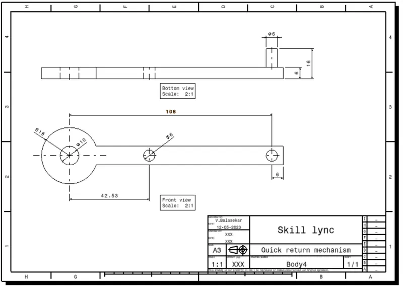
2d drawing
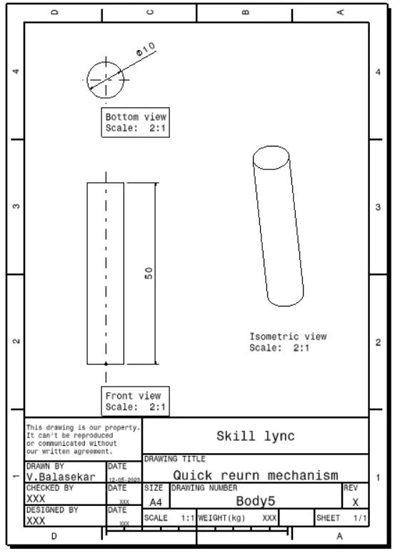
Body 5
Sketch workbench
Part Workbench
SPecification tree &Publication
2D drawing
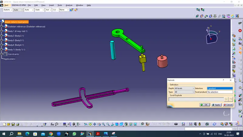
Assembly workbench
In assembly workbench ,Inserted all parts by existing Component
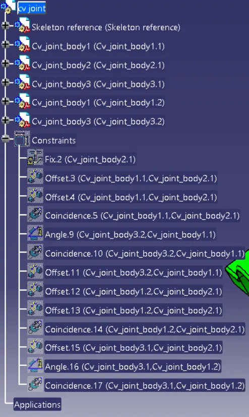
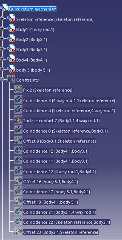
Created skeleton reference for assembly reference.Fixed body2 part as fixed component to assemble the other parts.Applied constraints to restrict the degrees of freedom of components on their respective work positions
Checked the fully constraints by explode and update

COnstraints &Specification tree
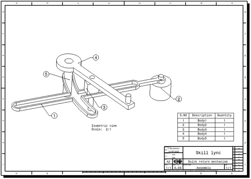
Assembly drawing of quick return mechanism
2. CV JOINT
Body 1
Sketch workbench
Part workbench
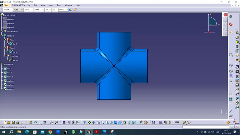
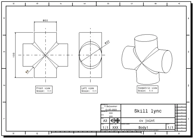
Specification tree & 2D Drawing
Body 2
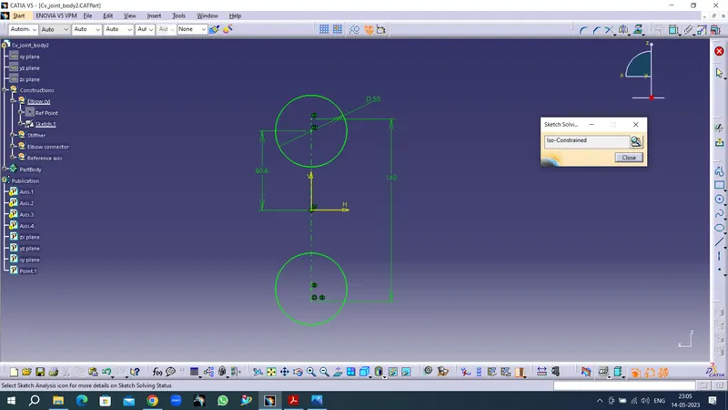
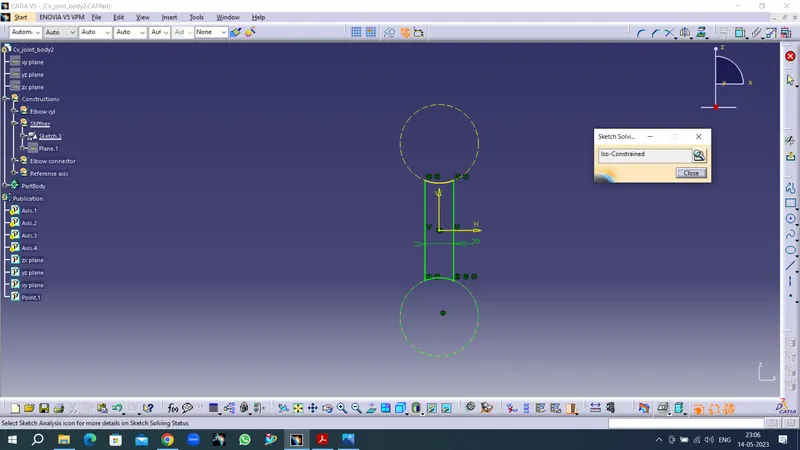
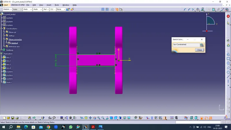
Sketch workbench
Part workbench
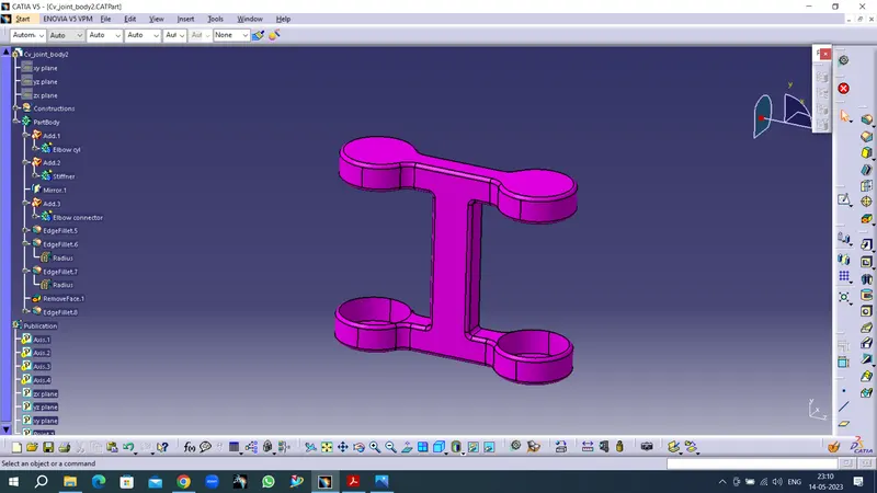
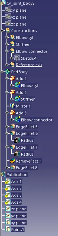
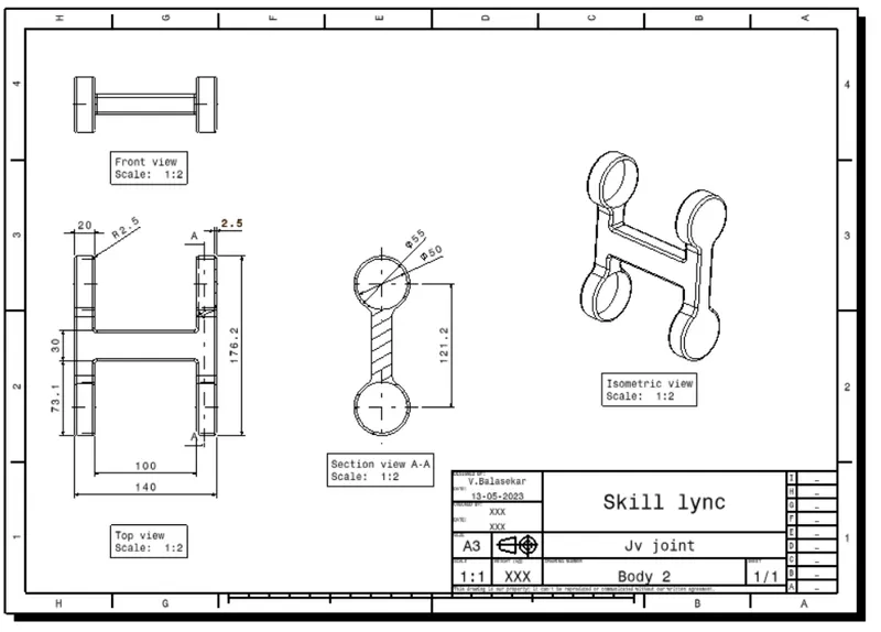
Specification tree 2d drawing
Body 3
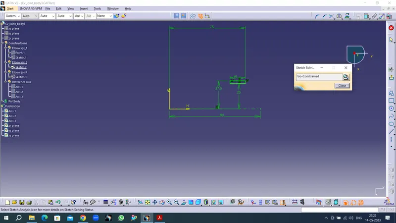
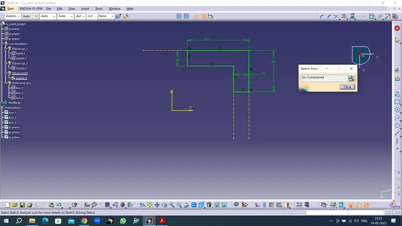
Sketch workbench
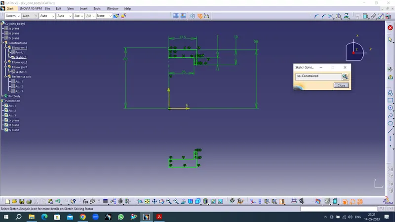
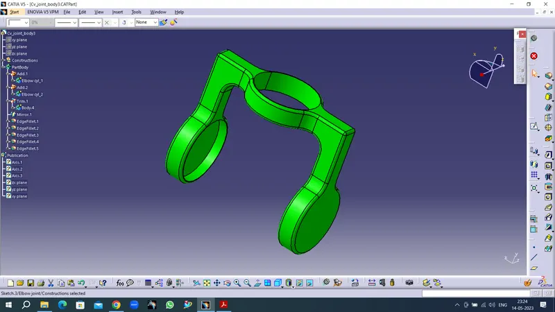
Part workbench
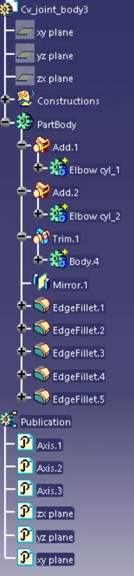
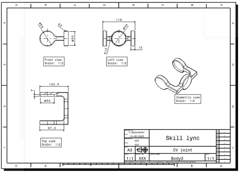
Specification tree 2D drawing
Assembly workbench
Explode and update
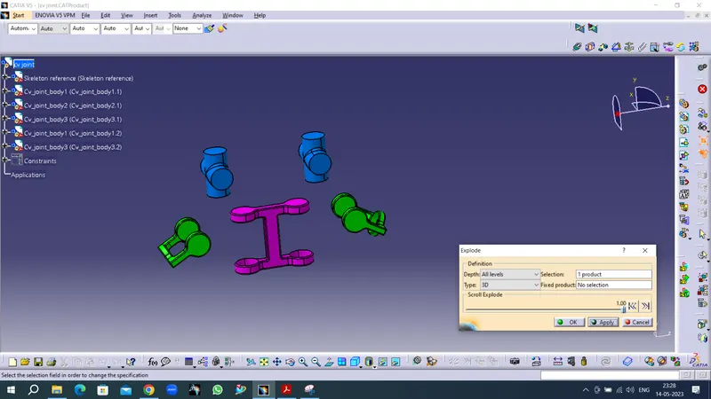
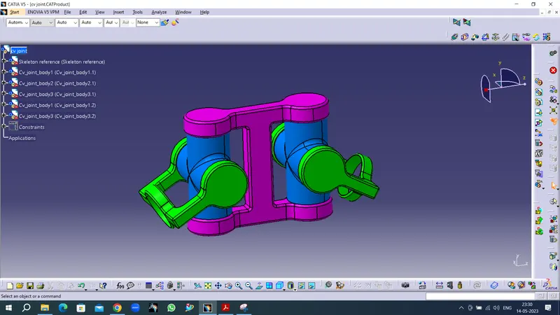
Specification tree