Week 7 Challenge - Assembly Workbench
Quick Return Mechanism
Aim:
To create the Quick return mechanism parts and assembles it in Assembly workbench with all the necessary constrains.
Working Procedure:
Based on the given sketch data we create every part in part workbench step by step.
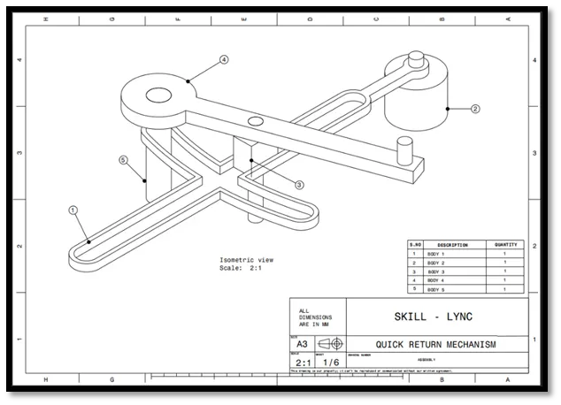
First create the Lever, as per given sketch data we sketch the lever and pad it as per the dimension.
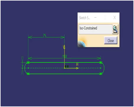
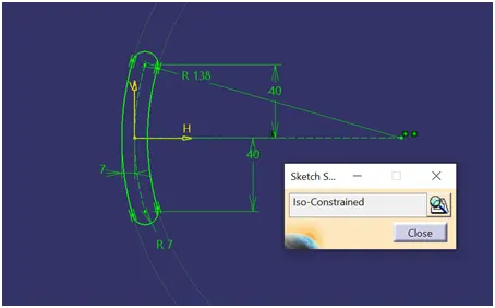
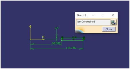
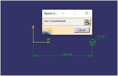
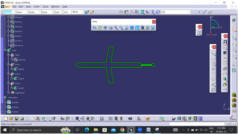
Then create the axis line in Surface workbench as necessary area. Save it as Lever.
Next Part: Base Block
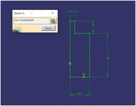
Using Revolve options create the solid part and name it as Base block. Using Axis line command provide centre axis of the block.
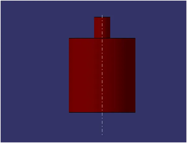
Next Part: Moving Rod, Using sketch option create the 2d sketch of moving rod.
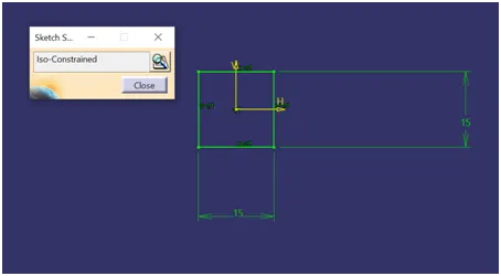
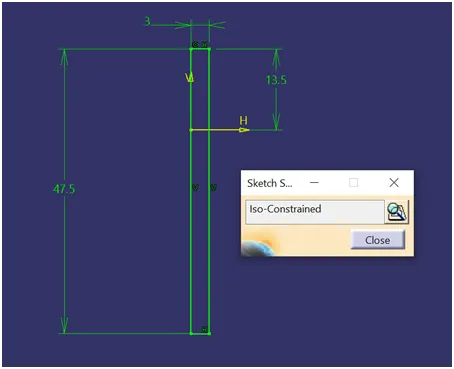
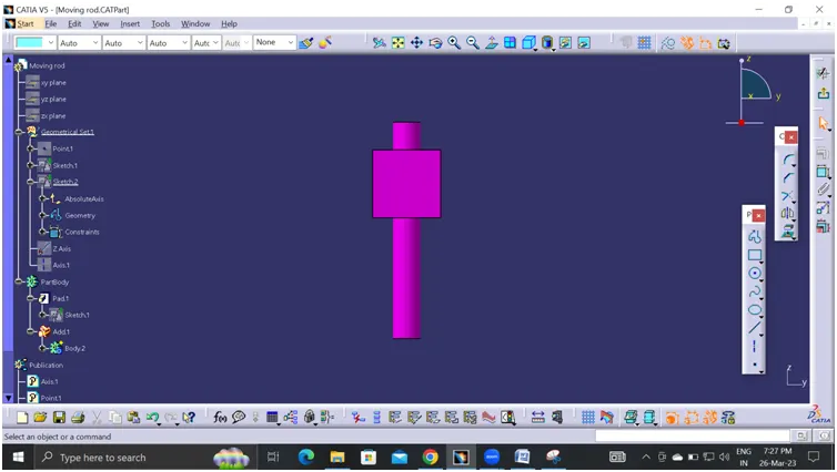
Using Pad option create the moving rod and using union trim both part to make a single element.
Next Part: Supporting Rod
Using Sketch command 2d drawing created.
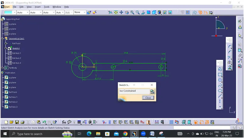
Using multiple pad option create a part body and name it as Support Rod. Using axis line command, necessary area axis created.
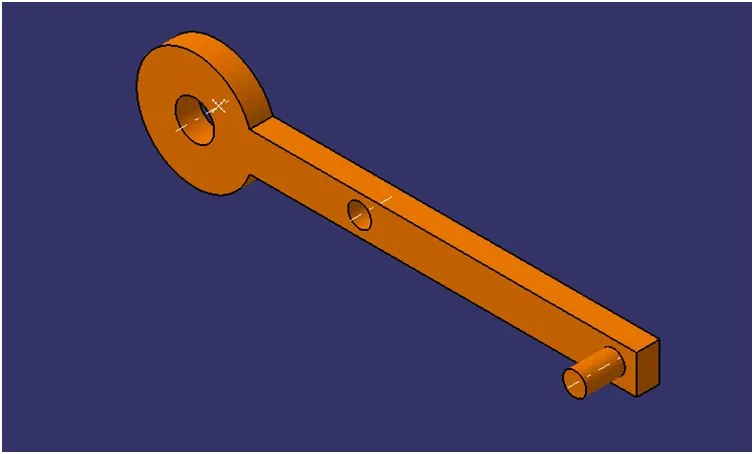
Next Part: Pin
Using Sketch command created the 2d sketch of pin and using pad option created a part body name it as pin and created the axis line.
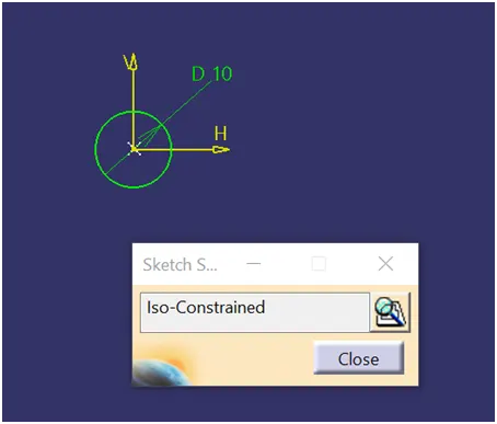
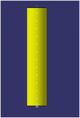
Now Work on the assembly workbench.
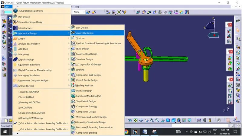
Import all the created parts in the assembly workbench using Existing component command option.
Now going to constrain the component one by one. Before that manipulate all the parts in different direction and hide the entire component except the lever and base block.
Step 1: Fix the lever using fix constrain, so that the lever can't move in space.
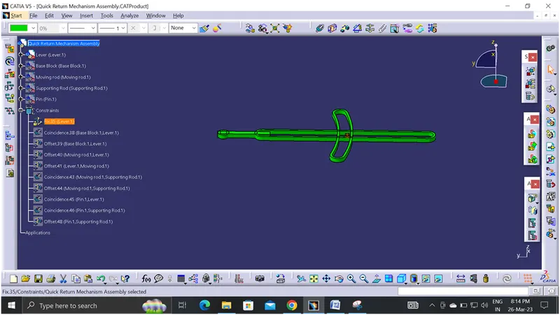
Step 2: Using Coincidence constrain between the Base block and lever to make a axis alignment. And later provide offset constrain to the block face and lever down face.
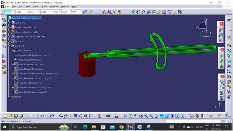
Step 3: Now unhide the moving rod and using offset constrains to make a contact between the moving rod side face with lever side face and also one more offset constrain between moving rod bottom face to lever bottom face.
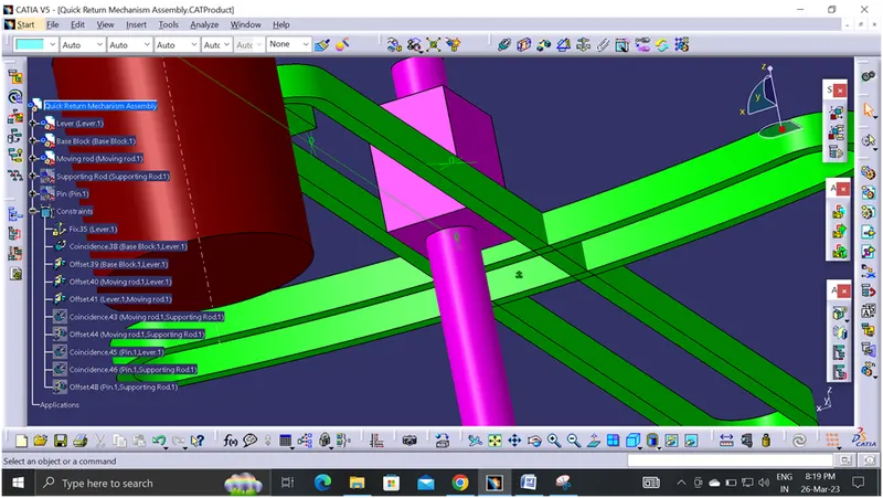
Step 4: Now unhide the supporting rod, and make a coincidence constrain between Moving rod axis and support rod axis. Then provide the offset constrain between supporting rod bottom face and moving rod face.
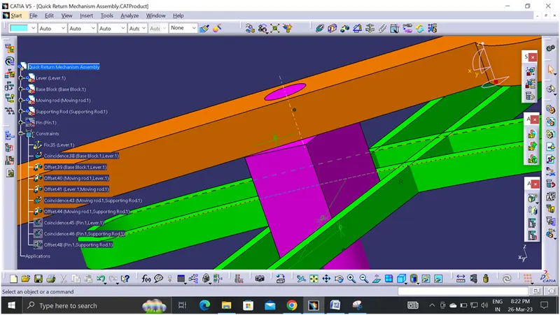
Step 5: Unhide the Pin and the pin going to contact between lever and supporting rod. So we provide coincidence constrain to the pin axis to the lever axis first later coincidence constrain between pin axis and supporting rod axis.
Then offset constrain given to contact between the pin top face to support rod top face.
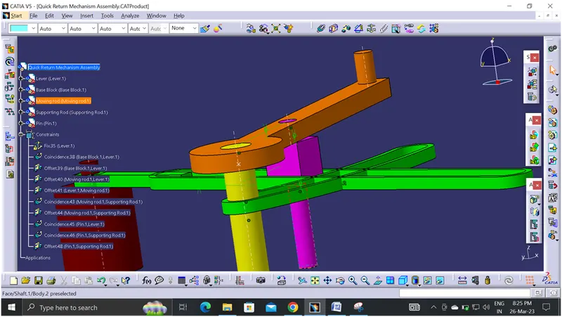
All the necessary constrain are provided, for checking purpose we explode the entire parts using explode command. Now the parts are separate in different direction.
Now click the update button all the parts are rearrange its original position based on the given constrain.
Step 6: Drafting sheet prepared for every component and save it in same folder.
Conclusion:
Quick release mechanism are created in assembly workbench with all necessary constrain.
CV Joint
Aim:
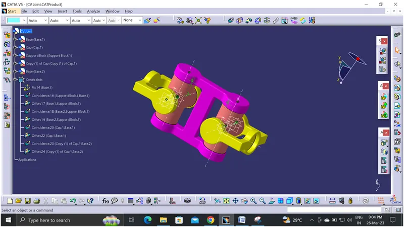
To create the CV Joint parts and assembles it in Assembly workbench with all the necessary constrains.
Working Procedure:
Based on the given sketch data we create every part in part workbench step by step.
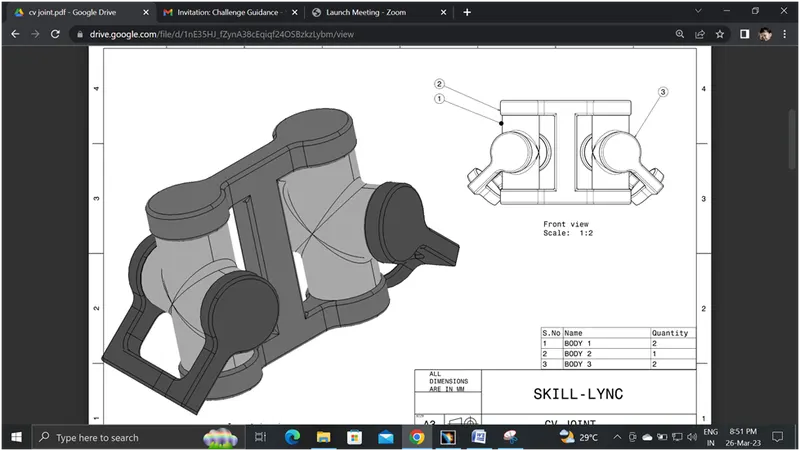
First create the Base, as per given sketch data we sketch the base and pad it as per the dimension.
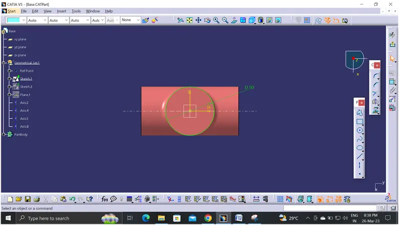
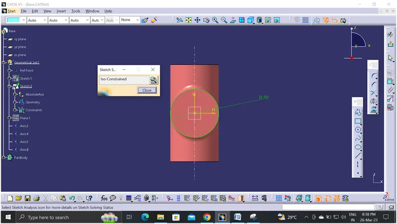
Then create the axis line in Surface workbench as necessary area. Name it as Base.
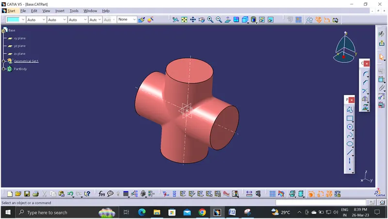
Next Part: Support Block
Skecth the 2d drawing as per the given dimension.
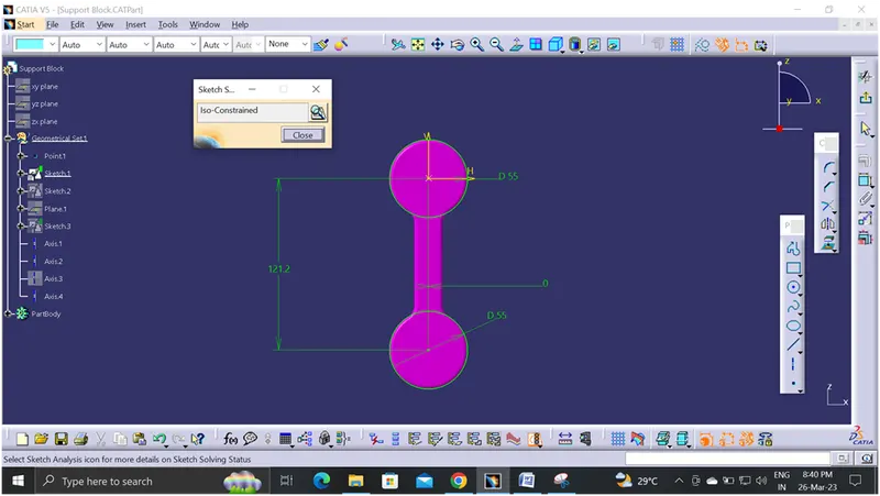
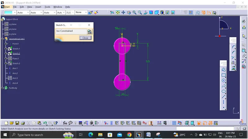
Using pad options create the solid part and name it as Base block. Using Axis line command provide centre axis of the block.
Then create a plane at 70mm distance and mirrored the part and join both.
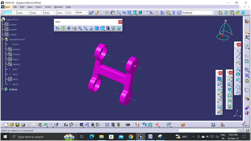
Next Part: Cap, Using sketch option create the 2d sketch of Cap.
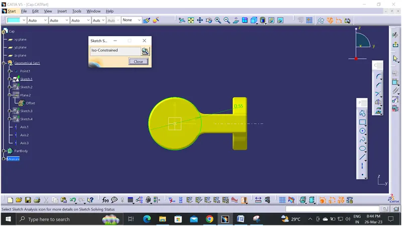
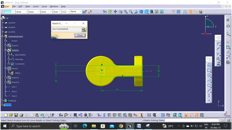
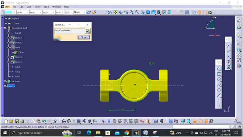
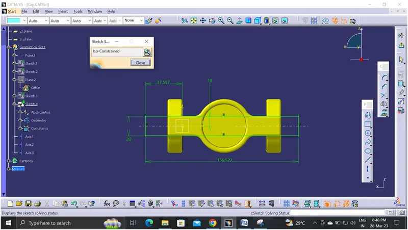
Using Pad option create the Cap and using union trim both part to make a single element. Now mirrored the component on other side in previous method. Then draw another sketch to and pad the sketch to complete the part.
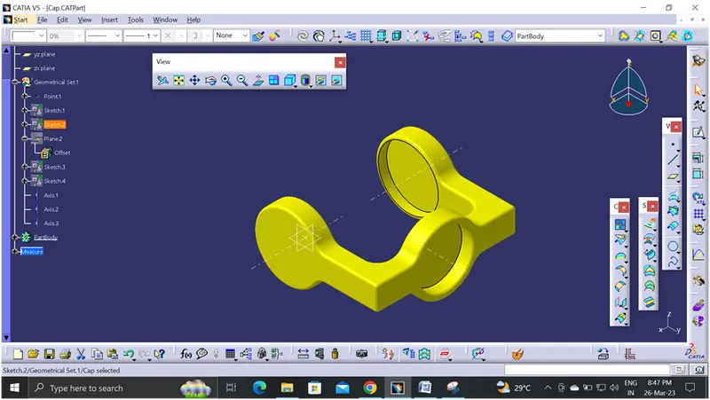
Now Work on the assembly workbench.
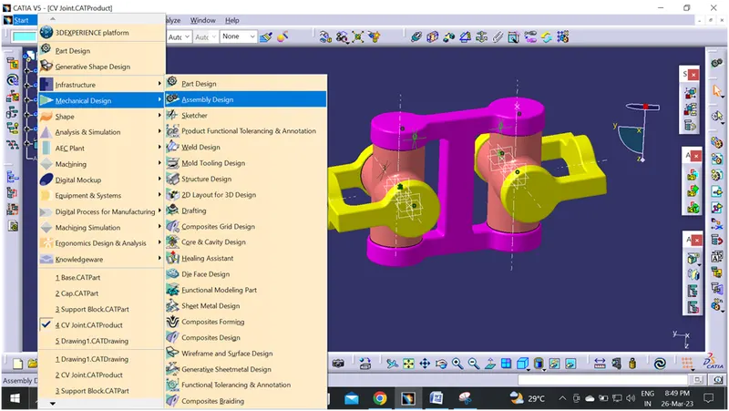
Import all the created parts in the assembly workbench using Existing component command option.
Now constrain the component one by one. Before that manipulate all the parts in different direction and hide the entire component except the Base and cap. In this challenge we need two base and two cap.
We created single part each now copy the base and past special the product tab to make a copy of base. Same step follows for cap copy.
Step 1: Fix the Base using fix constrain, so that the Base can't move in space.
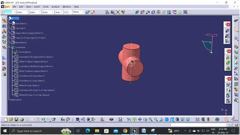
Step 2: Using Coincidence constrain between the Base and support block axis to make a axis alignment. And later provide offset constrain to the block face and support block down face.
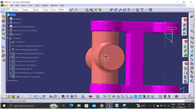
Step 3: Now unhide the base 2 follow the previous step of constrain.
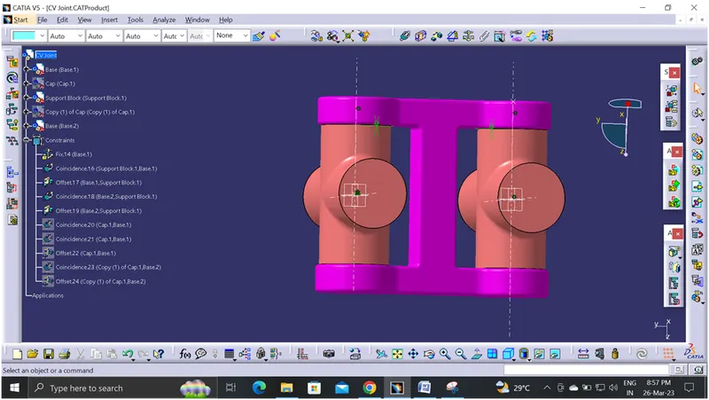
Step 4: Now unhide the Cap 1, and make a coincidence constrain between Cap 1 axis and Base 1 axis. Then provide the offset constrain between Cap 1 bottom face and Base 1 top face.
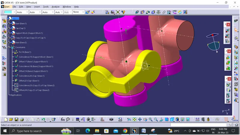
Step 5: Unhide the Cap 2 and follow the previous step of constrain for connect the Cap 2 with base 2.
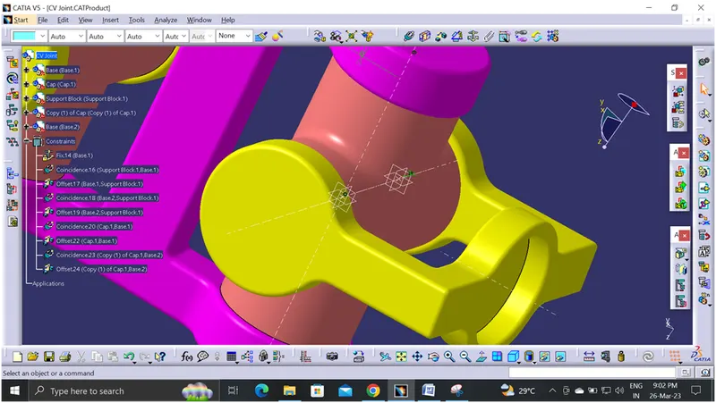
All the necessary constrain are provided, for checking purpose we explode the entire parts using explode command. Now the parts are separate in different direction.
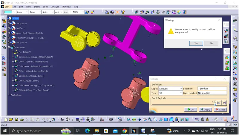
Now click the update button all the parts are rearrange its original position based on the given constrain.
Step 6: Drafting sheet prepared for every component and save it in same folder.
Conclusion:
CV Joint are created in assembly workbench with all necessary constrain.