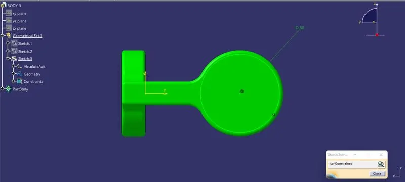
Week 7 Challenge - Assembly Workbench
REPORT ON QUICK RETURN MECHANISM ASSEMBLY
OBJECTIVE:
The aim of Challenge to Create Quick Return Mechanism Assembly and Drafting by taking input of 2D Drawing PDFs.
QUICK RETURN MECHANISM:
A quick return mechanism is an apparatus to produce a reciprocating motion in which the time taken for travel in return stroke is less than in the forward stroke. It is driven by a circular motion source (typically a motor of some sort) and uses a system of links with three turning pairs and a sliding pair. A quick-return mechanism is a subclass of a slider-crank linkage, with an offset crank.
Quick return is a common feature of tools in which the action is performed in only one direction of the stroke, such as shapers and powered saws because it allows less time to be spent on returning the tool to its initial position.
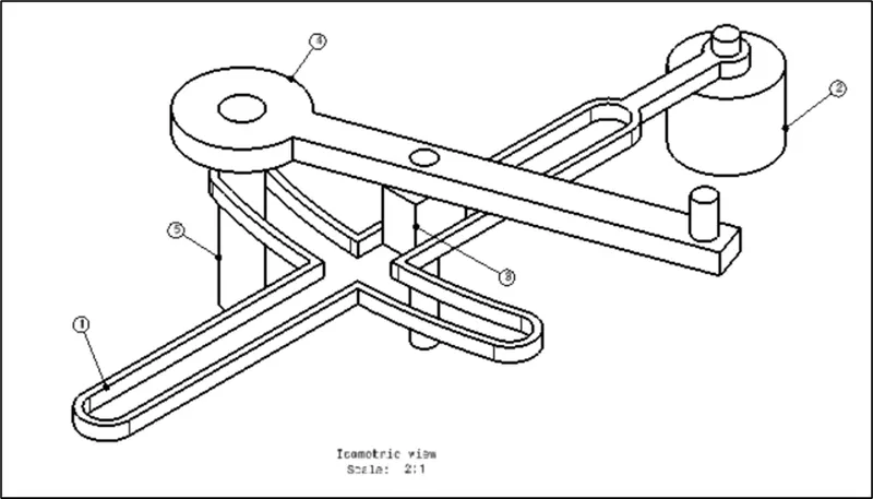
The above picture shows an Assembly of Quick return Mechanism with Pointing the Parts with numbers.
1.BASE FRAME:
Base Frame is shell type structure which supports for remaining components to Guide the Crank to move in Linear direction.
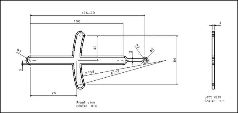
The above picture shown views of Base frame. Below steps explains how created this Base Frame along with Pictures.
2. HOLDER FOR FRAME:
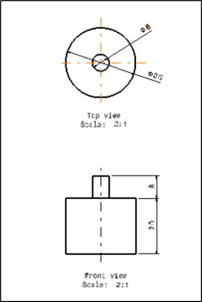
The above Picture shown Holding Frame which will connect end of the Base Frame. And will support to rotate.
3. SLIDER:
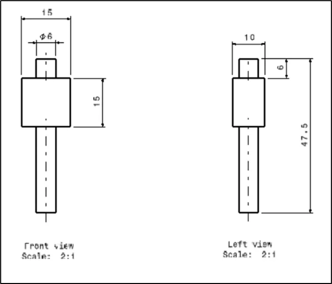
The above Picture shown Slider which slides in Base frame slots in linear motion.
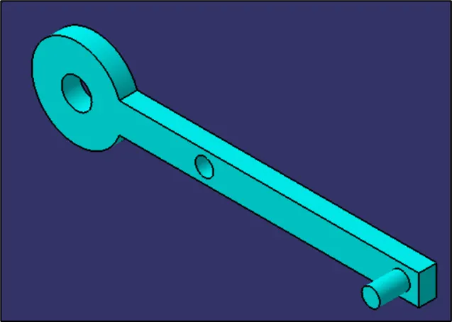
4. CRANK:
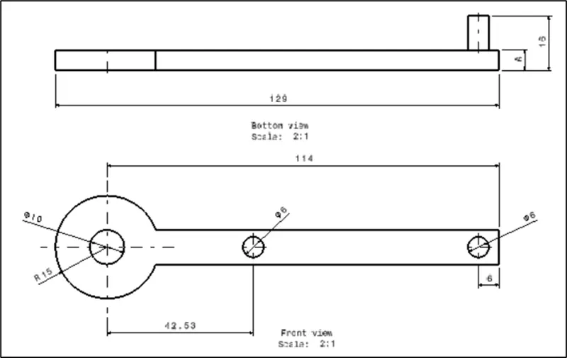
The above Picture shown Crank which connects Holder and Slider. This component is main for this mechanism. This will change rotational motion into linear motion.
5. CRANK PIN:
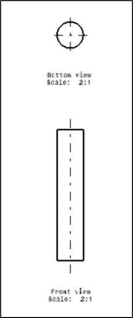
Crank pin is connected to Crank end and this also slides in Base Frame.
QUICK RETURN MECHANISM USES:
- It is used in the shaper Machine for flattening the workpiece.
- Same is used in the Slotter and Planer Machine.
- It is also used in the Screw press, Mechanical actuator, and Rotary combustion Internal Engine.
3D IMAGES:
ASSEMBLY
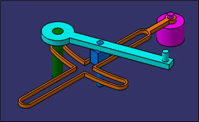
COMPONENTS
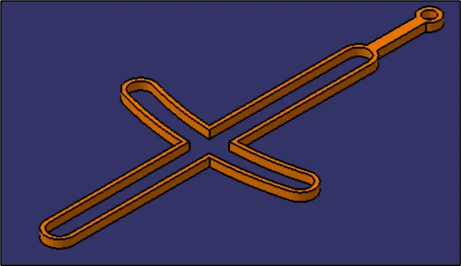
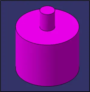
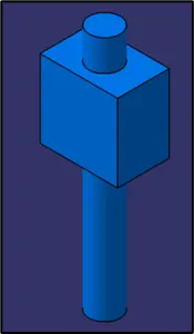
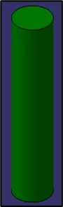
After working with the assembly workbench in CATIA. I got to know various relations and constraints that would be joined together to make a full working assembly.
And I got to know how to work with parts and their assembly and also the different tools used for assembly.
ASSEMBLY VIEWS & FEATURE TREES:
FRONT VIEW
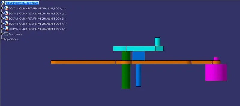
SIDE VIEW
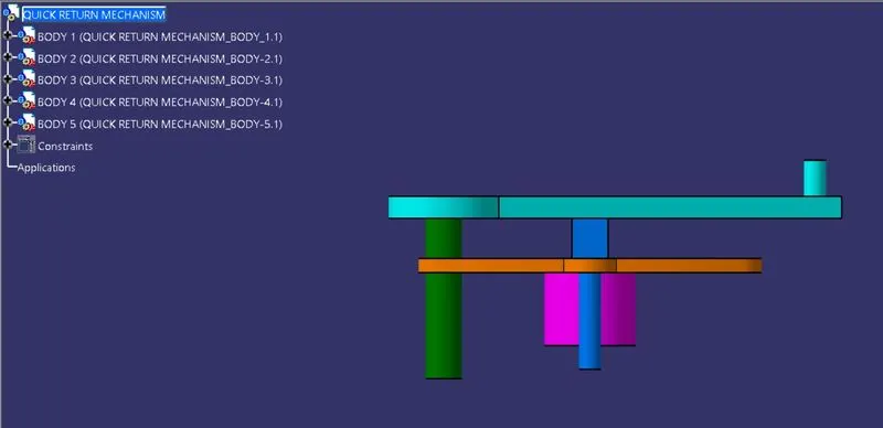
TOP VIEW
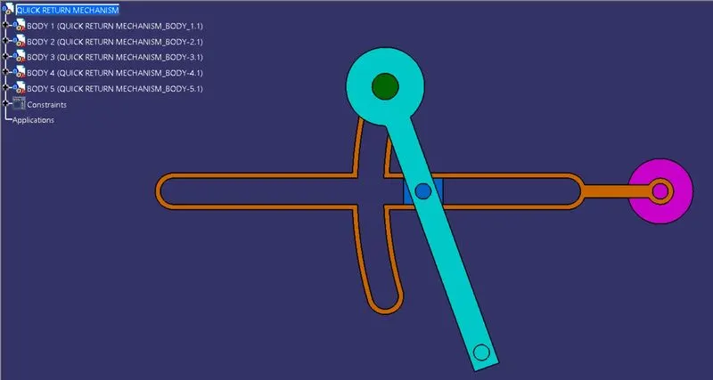
ISOMETRIC VIEW
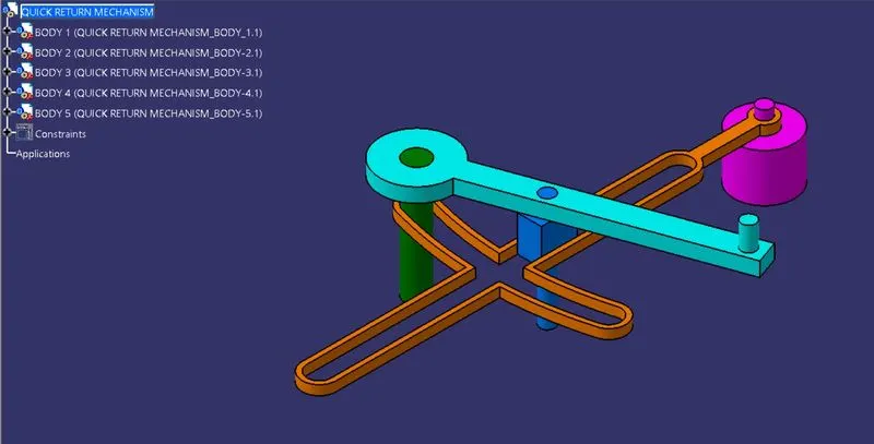
FEATURE MANAGER TREE
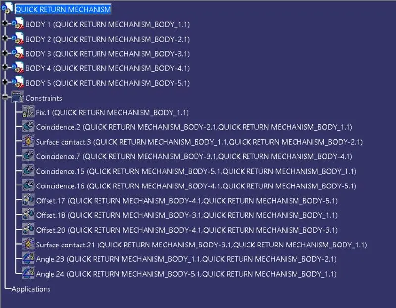
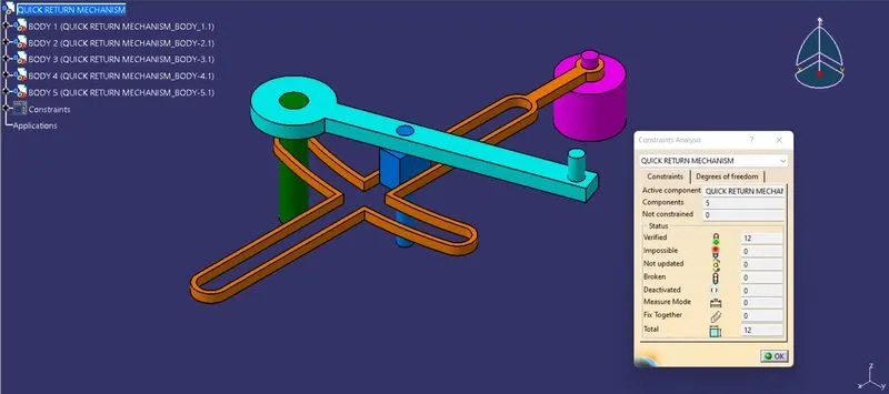
CONSTRAINTS
BODY 1 VIEWS, FEATURE TREE & SKETCH:
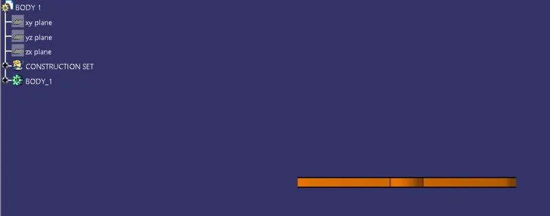
FRONT VIEW
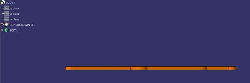
SIDE VIEW
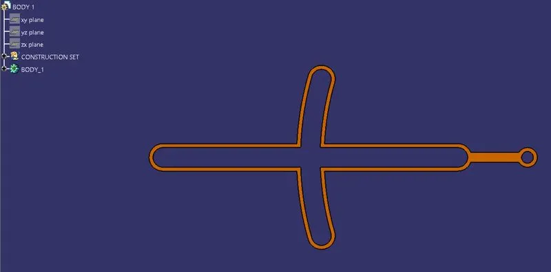
TOP VIEW
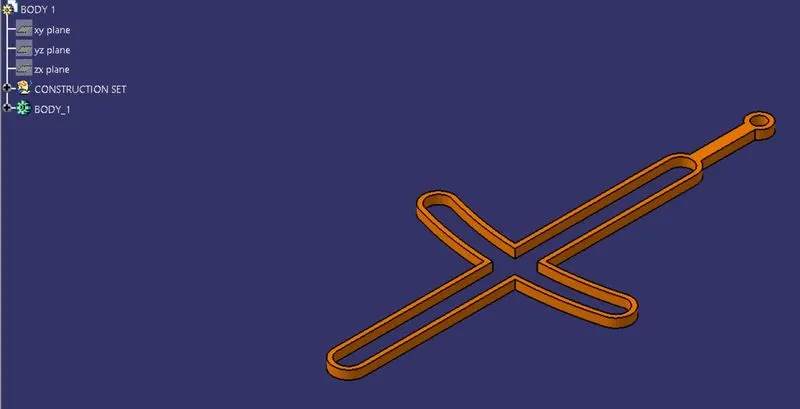
ISOMETRIC VIEW
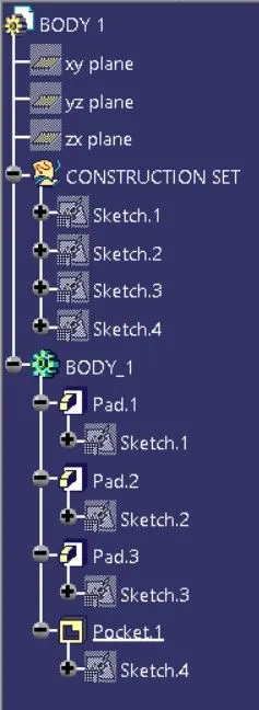
FEATURE MANAGER TREE
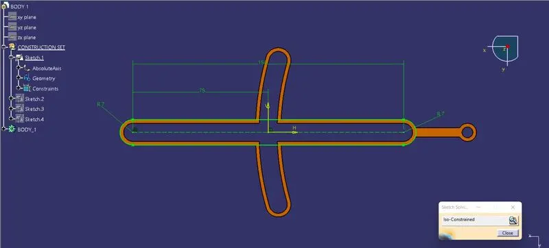
SKETCH_1
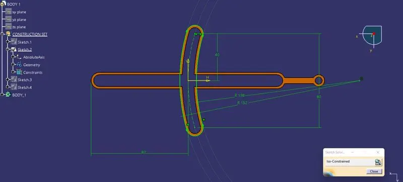
SKETCH_2
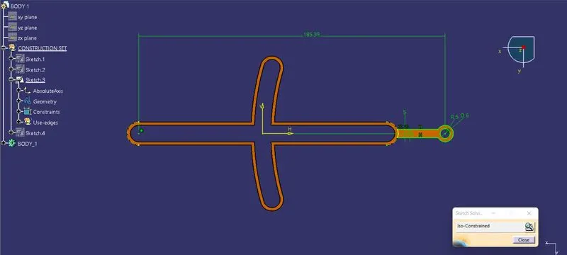
SKETCH_3
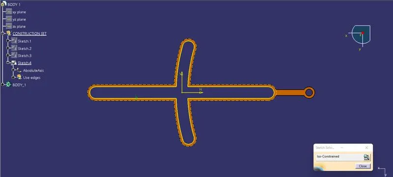
SKETCH_4
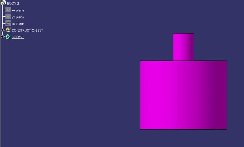
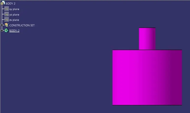
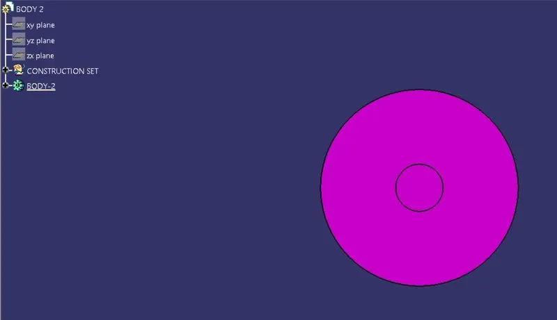
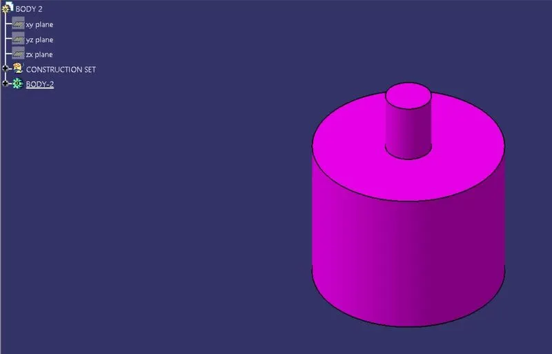
BODY 2 VIEWS, FEATURE TREE & SKETCH:
FRONT VIEW
SIDE VIEW
TOP VIEW
ISOMETRIC VIEW
FEATURE MANAGER TREE
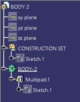
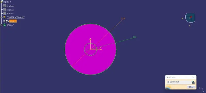
SKETCH_1
BODY 3 VIEWS, FEATURE TREE & SKETCH:
FRONT VIEW
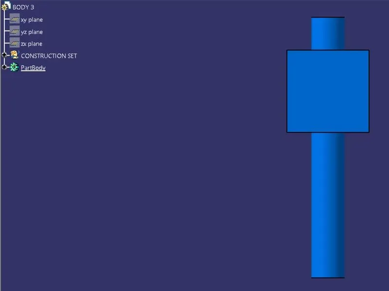
SIDE VIEW
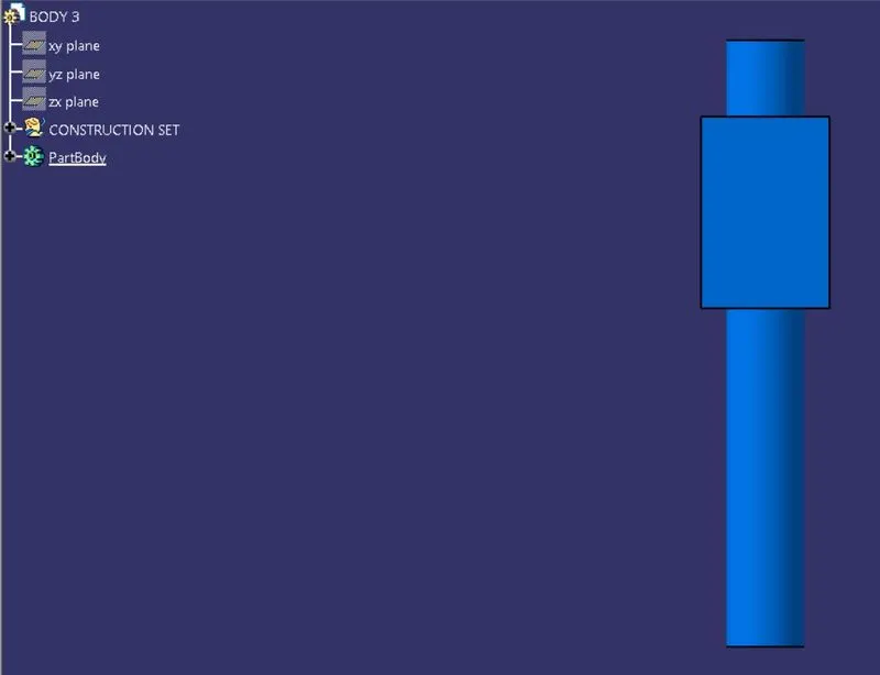
TOP VIEW
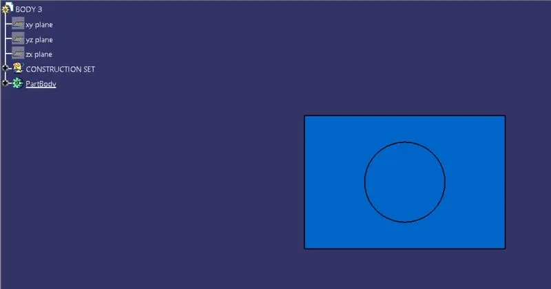
ISOMETRIC VIEW
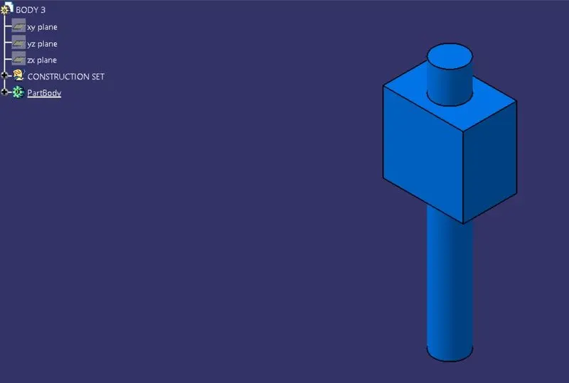
FEATURE MANAGER TREE
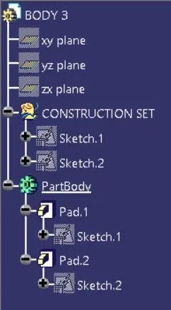
SKETCH_1
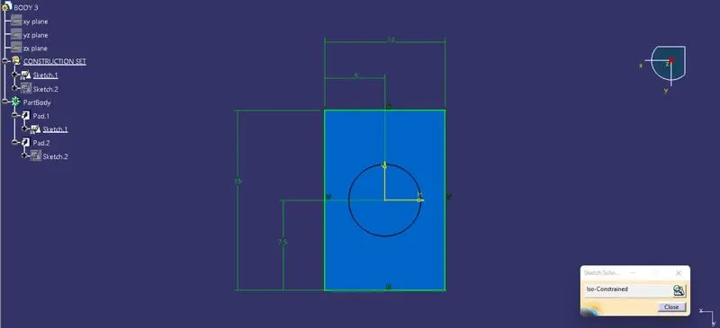
SKETCH_2
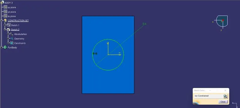
BODY 4 VIEWS, FEATURE TREE & SKETCH:
FRONT VIEW
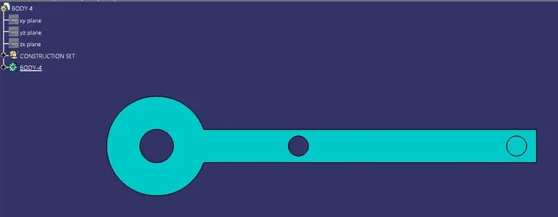
SIDE VIEW
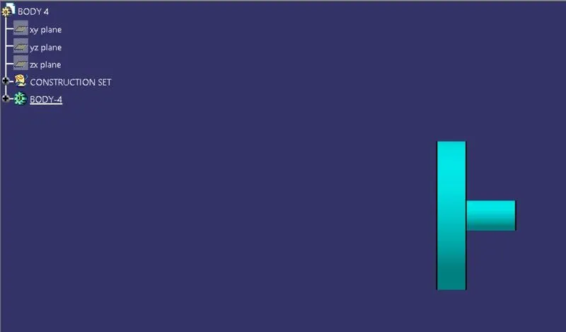
TOP VIEW
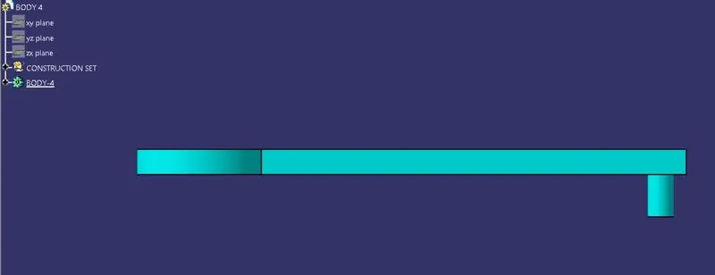
ISOMETRIC VIEW
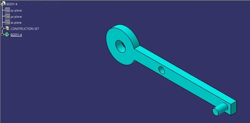
FEATURE MANAGER TREE
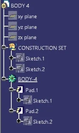
SKETCH_1
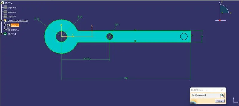
SKETCH_2
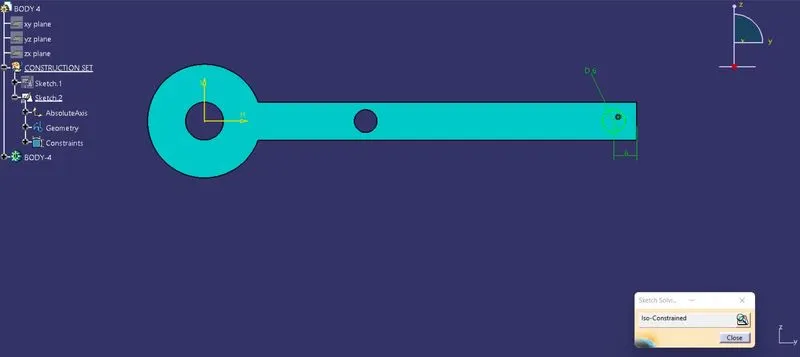
BODY 5 VIEWS, FEATURE TREE & SKETCH:
FRONT VIEW
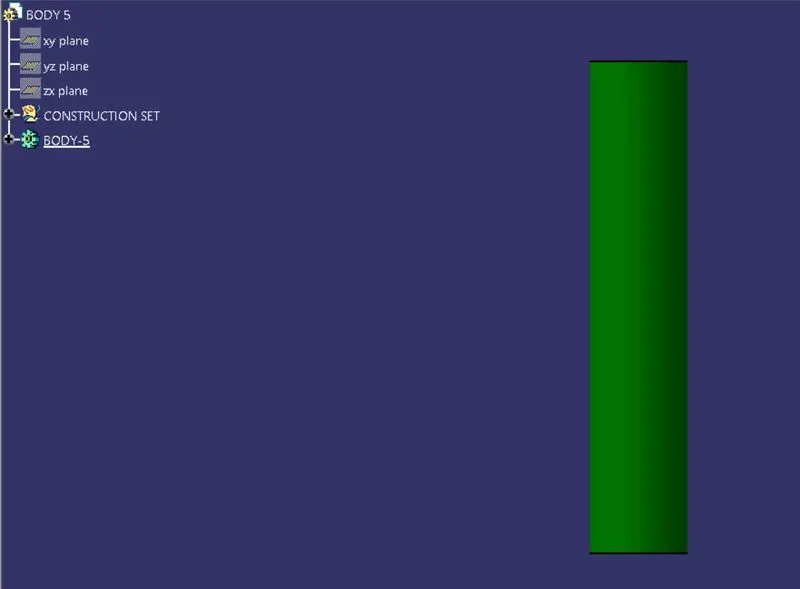
SIDE VIEW
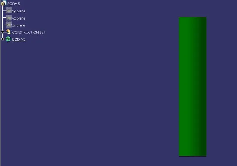
TOP VIEW

ISOMETRIC VIEW
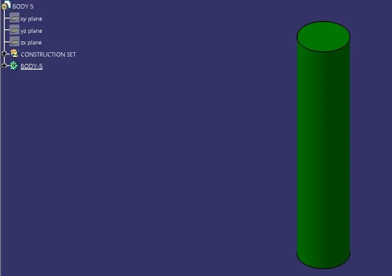
FEATURE MANAGER TREE
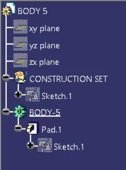
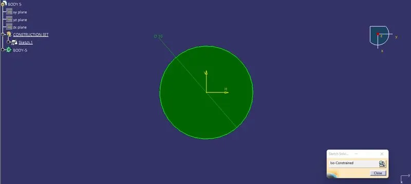
SKETCH_1
REPORT ON CV-JOINT ASSEMBLY
OBJECTIVE:
The aim of Challenge to Create CV-Joint Assembly Model and Drafting by taking input of 2D drawing PDFs.
CV-JOINT:
Constant-velocity joints (also known as homokinetic or CV joints) allow a drive shaft to transmit power through a variable angle, at constant rotational speed, without an appreciable increase in friction or play. They are mainly used in front-wheel drive vehicles. Modern rear-wheel-drive cars with independent rear suspension typically use CV joints at the ends of the rear axle half shafts and increasingly use them on the drive shaft.
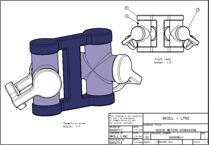
The above picture shows an Assembly of CV-Joint with Pointing the Parts with numbers.
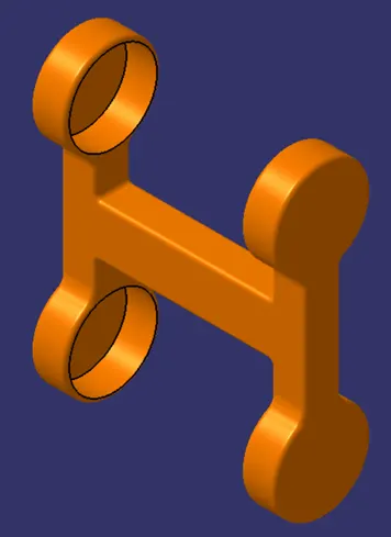
- CONJUNCTION PART OR 'I' TYPE COMPONENT:
Conjunction Part is the Mediator for Support and hold the Energy Converging parts. It is like Base component for remaining Parts as well as Assembly.
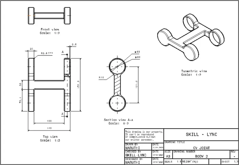
The above picture shown views of Conjunction Part It looks like an I shape which is having High strength.
2. CIRCULAR CONVERGING PART:
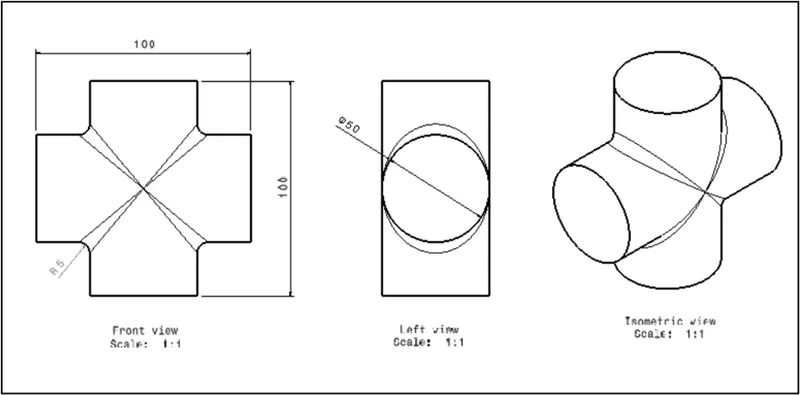
The above Picture shown Circular Converging part which will supports to transfer energy from one side to other. This Part rotates in Multi direction to transfer rotational motion angularly. This Part will Made by welding of Circular rod in Cruciform shape.
3. VERTICAL MOVEMENT PART OR TYPE 'C' PART:
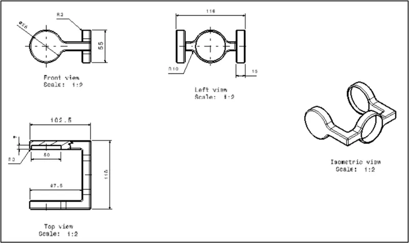
The above Picture shown C type Part which Connects Shaft and CV joint.
CV-JOINT USES:
The CV joints are needed to transfer the torque from the transmission to the drive wheels at a constant speed, while accommodating the up-and-down motion of the suspension. In front-wheel drive cars, CV joints deliver the torque to the front wheels during turns.
3D IMAGES:
ASSEMBLY
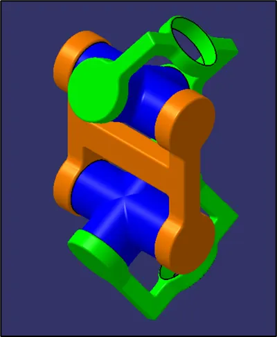
COMPONENTS
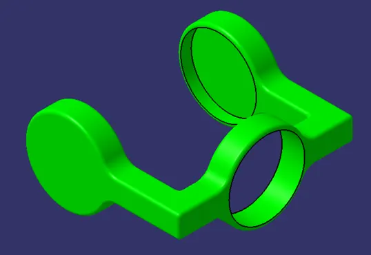
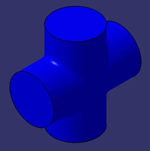
After working with the assembly workbench in CATIA. I got to know various relations and constraints that would be joined together to make a full working assembly.
And I got to know how to work with parts and their assembly and also the different tools used for assembly.
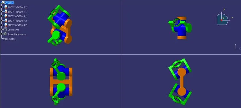
ASSEMBLY VIEWS & FEATURE TREES:
FRONT VIEW
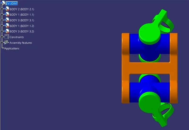
SIDE VIEW
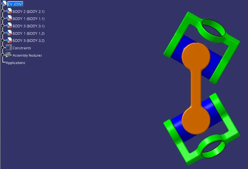
TOP VIEW
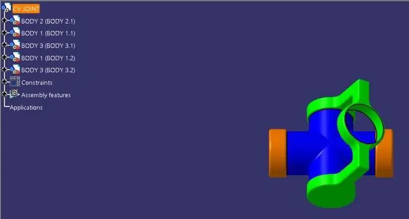
ISOMETRIC VIEW
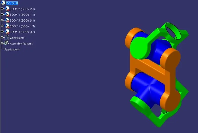
COLOR VARIOUS IMAGE
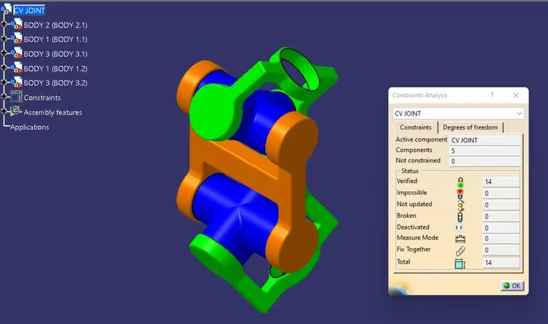
ASSEMBLY CONSTRAINED
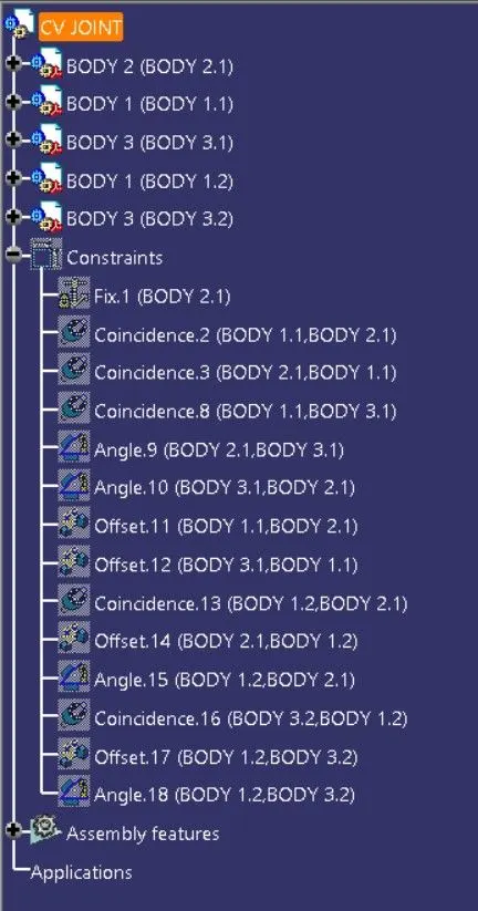
ASSEMBLY_FEATURE MANAGER TREE
BODY 1 VIEWS, FEATURE TREE & SKETCH:
FRONT VIEW
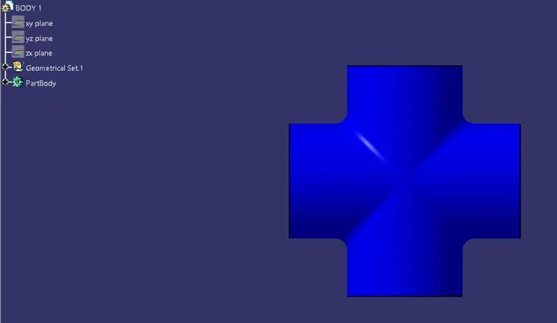
SIDE VIEW
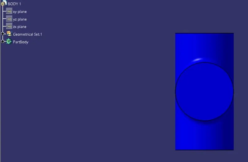
TOP VIEW
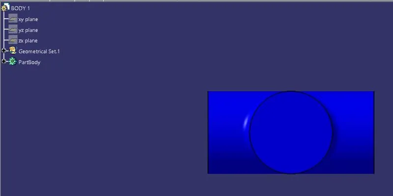
ISOMETRIC VIEW
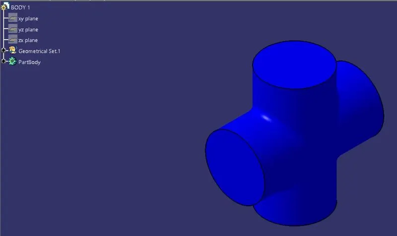
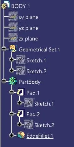
FEATURE MANAGER TREE
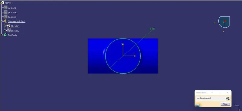
SKETCH_1
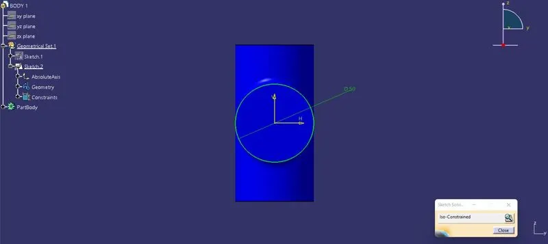
SKETCH_2
BODY 2 VIEWS, FEATURE TREE & SKETCH:
FRONT VIEW
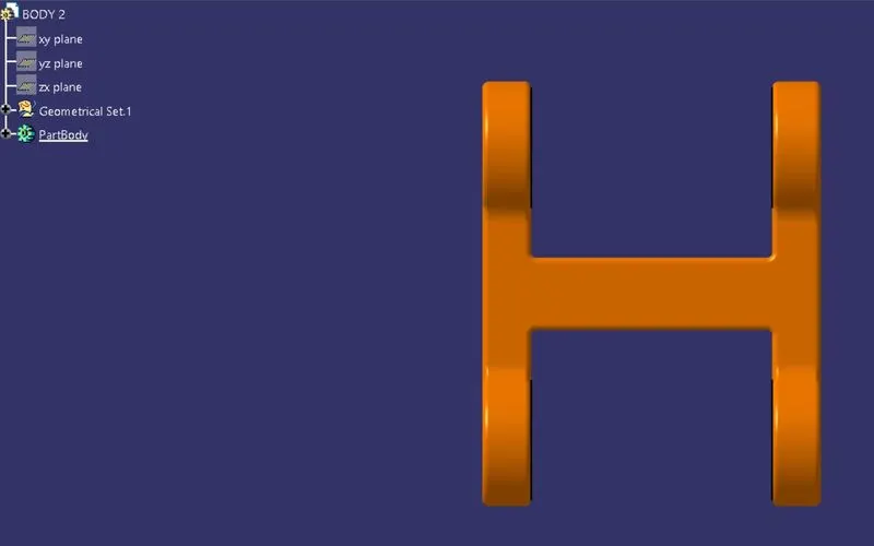
SIDE VIEW
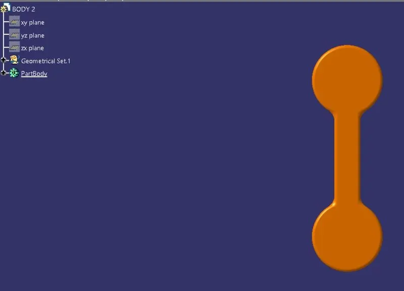
TOP VIEW
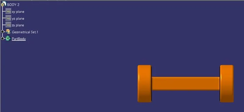
ISOMETRIC VIEW
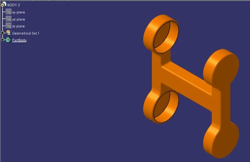
FEATURE MANAGER TREE
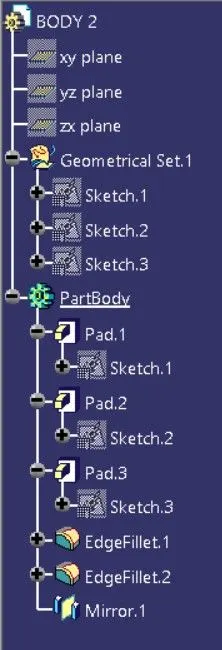
SKETCH_1
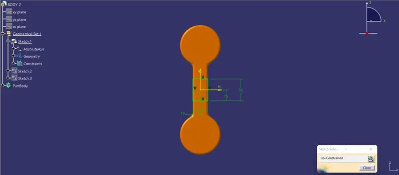
SKETCH_2
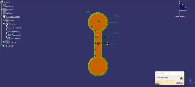
SKETCH_3
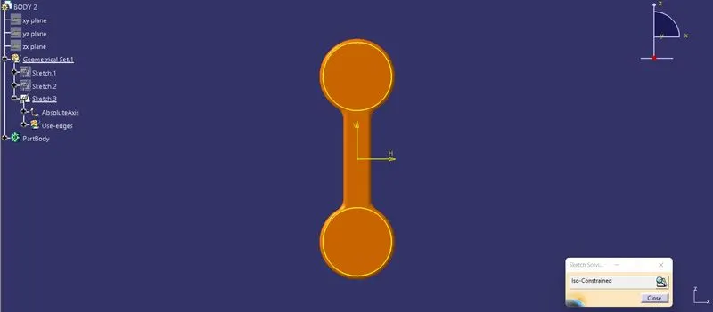
BODY 3 VIEWS, FEATURE TREE & SKETCH:
FRONT VIEW
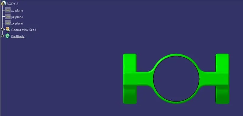
SIDE VIEW
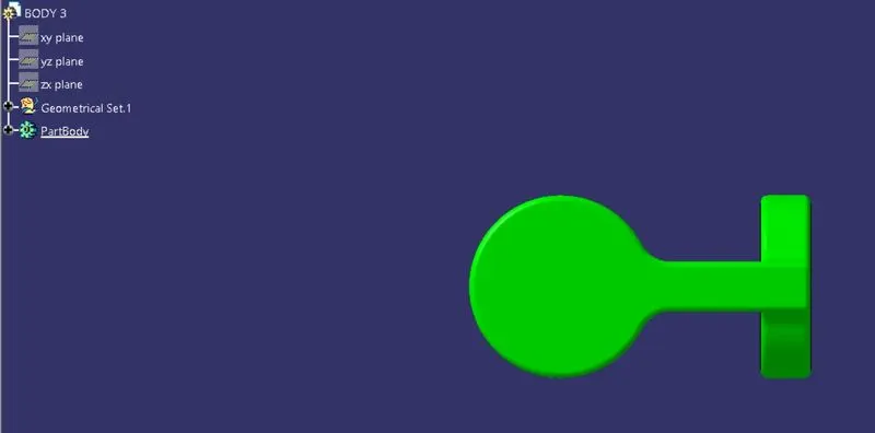
TOP VIEW
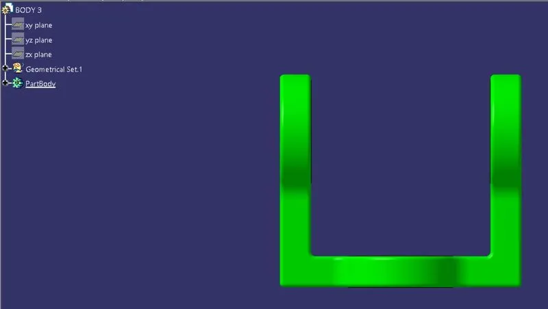
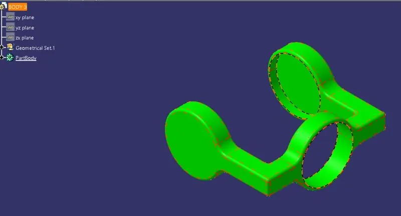
ISOMETRIC VIEW
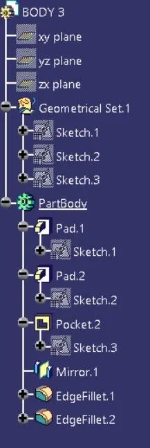
FEATURE MANAGER TREE
SKETCH_1
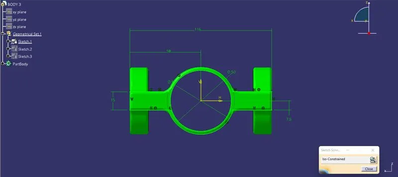
SKETCH_2
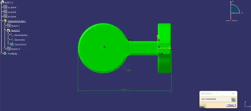
SKETCH_3