Radar Mast & Final Assembly of Yacht
1. Radar Mast:
2. Predator Yacht Final Assembly:
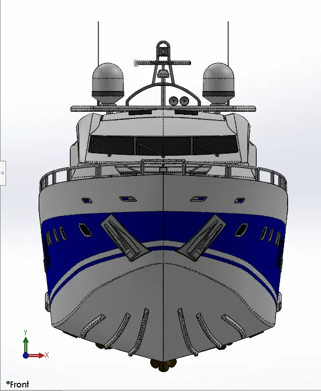
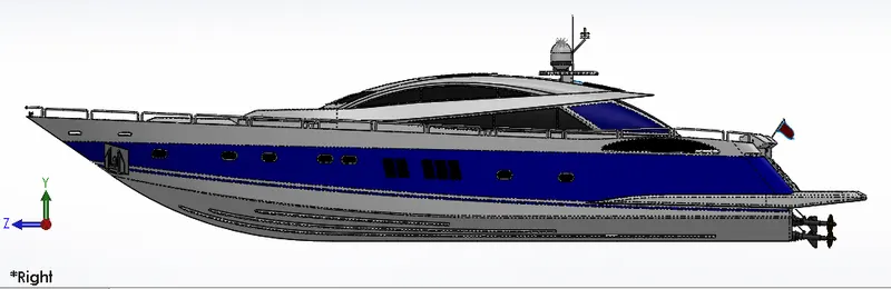
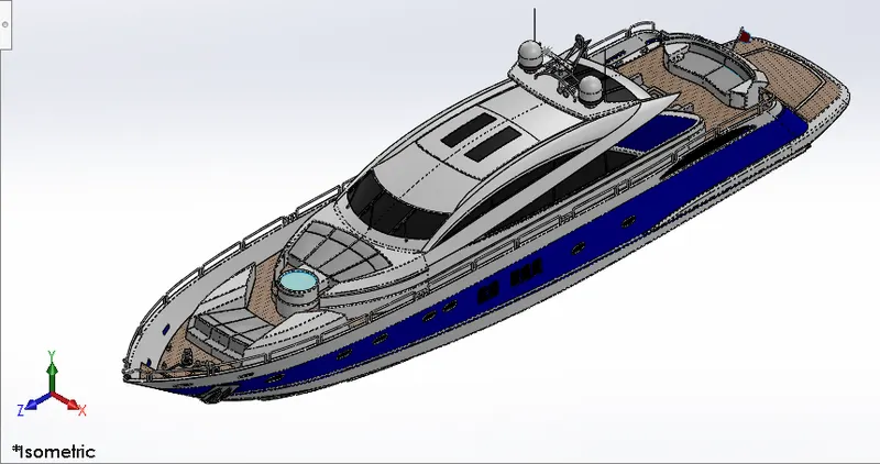
3D Modelling of Predator Yacht
objective:
The main objective of this Project is:
- To create Individual Part models of Predator Yacht by using Solid works
- To Create Assembly by using all individual Parts
- Add Appearances and Decals
Introduction:
Solid works is one of the prominent modelling software uses to model 3D Parts using 2D sketch. It also has options Like Appearances to specify the Material and look for the model which we create. It has Add-in features like Photoview360 which helps in Rendering of the final model to make it look as Photorealistic. In this Project we learned about Detailed design of Predator yacht Parts and Modelling final Assembly.
Design Methodology/approach:
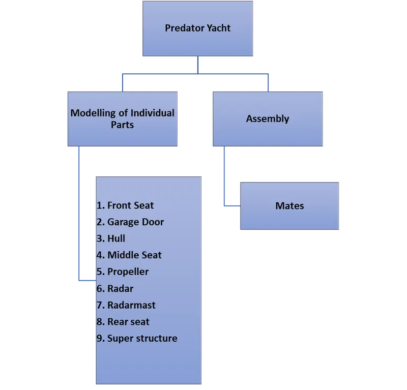
Front Seat:
The Front Seat is mounted on the Hull Deck surface in front of the superstructure.
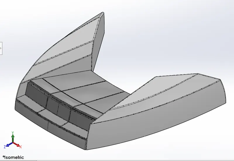
Features used to create Front Seat:
- Sketch
- Reference Plane
- Surface Extrude
- Surface Sweep
- Surface Loft
- Surface Fill
- Surface Trim
- Surface Knit
- Revolve Boss
- Extrude Cut
- Extrude Cut Thin
- Dome
- Fillet
- Chamfer
- Mirror
- Appearances
Sketch:
The sketch is 2D representation of model. These are known as entities in solid works. E.g., Line, Circle, Rectangle, Spline, Ellipse etc.
Reference Plane:
Reference Plane is extra plane created by reference of existed plane, face, point, line or edge. By using two references we can create a plane.
Surface Extrude:
Surface Extrude feature is used to create a new surface by selecting a line or spline and by define the direction for extrude.
Sweep surfaces:
Sweep surfaces are surfaces that are generated from a section curve positioned along a path.
Surface Loft:
Loft surfaces are surfaces generated by multiple 3D curves or existing edges creating a smooth tangency between the selected curves.
Surface Fill:
The Fill surface feature constructs a surface path with any number of sides with in a boundary defined by existing model edges, sketches or curves including composite curves.
Surface Trim:
Primarily used to cut away material from surface and provides two modes: Standard and Mutual.
Surface Knit:
Surface Knit is used to Knit two free edges/open edges of the surface together. Also reduces the Gap between two edges of the surfaces.
Revolve Boss:
Create a sketch that contains one or more profiles and a center line or an edge to use as the axis around which the feature Revolve Tools.
Extrude Cut:
The feature is used to remove material from the 3D model. It is just opposite to Extrude Boss because it cuts a sketch profile while extruding. You can cut in both directions and mainly used for creating holes, channels, slots etc.
Extrude Cut Thin:
This Feature same as Extrude Cut but It has included thin feature selection. By click check box it will enable.
Dome:
This feature is majorly applied to faces. Select one or more planar or non-planar faces. You can apply dome to faces whose centroid lies outside the face. This allows you to apply domes to irregularly shaped contours.
Fillet:
This feature creates a rounded internal or external face on the part. You can fillet all the edges of a face or loops etc.
Chamfer:
A cut on the edge or corner of something that makes it slope slightly rather being perfectly square.
Mirror:
By using mirror faces with a midplane selected only the chosen faces with in the revolve will be mirrored. Mirroring bodies can be used whether in a single or multibody part and allows you to select solid geometry instead of features and faces in a body. In the fork part the one part is created and the other part is mirrored. Then the parts are manually combined.
Appearance:
An Appearance feature is used to define the color or material of a part. There are different scenes are available. We can choose by our requirement.
Garage Door:
The Garage Door is Placed Backside of Hull. The door is made for Garage which we used to park our vehicle like car.
The sketch for Garage door was imported from hull part drawing. By using save part external option. And then modified separately by using some of the features.
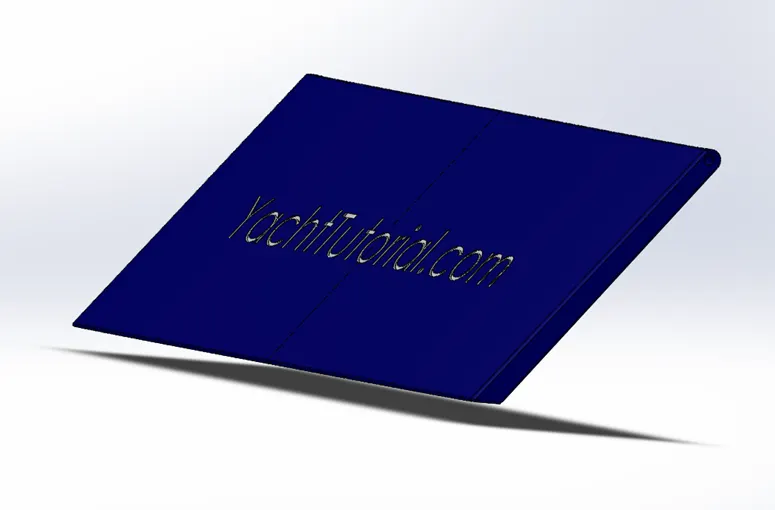
Features used to Garage Door:
- Extrude Cut
- Shell
- Fillet
- Mirror
- Appearances
Shell:
The shell feature is used to define the thickness of thin and thick shell elements.
Hull:
The Hull is main part for assembly. This is the bottom part for yacht floats on water and work as a base for remaining parts.
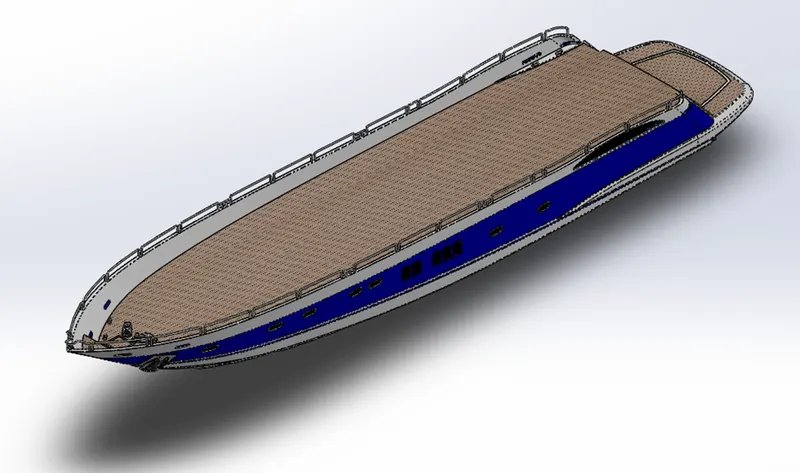
Features used to Create Hull:
- Sketch
- Projected Curve
- Surface Extrude
- Surface Loft
- Surface Fill
- Surface Trim
- Surface Knit
- Reference Plane
- Shell
- Extrude Boss
- Extrude Cut
- Fillet
- Chamfer
- Swept Boss
- Revolve Boss
- Dome
- Helix/Spiral
- Linear Pattern
- Delete Face
- Extrude boss Thin
- Extrude Cut Thin
- Split Line
- Mirror
- Appearances
Projected Curve:
Projected curve is a kind of 3D curve which is projected based on the two different 2D sketches.
Extrude Boss/Base:
This feature is used to convert a 2D sketch into a 3D model.
Helix/Spiral:
This feature is used to create springs by using a circle diameter and pitch distance.
Linear Pattern:
This feature is used to create number of instances linearly a copy of existing entity of body.
Delete Face:
This Feature is used to remove excess faces from the surface. It has options like Delete, Delete and Patch, Delete and Fill.
Extrude Boss Thin:
This is same as Extrude Boss but in this feature we no need to use of Closed sketch. Even by a single line we can create an extrude. And same as extrude cut thin but in this feature, material will be added instead of removing.
Split Line:
This feature use in sketching. If we want to split an entity into two entities by adding a point then split line is used.
Middle Seat:
It is placed Between the super structure and Rear seat on Hull surface.
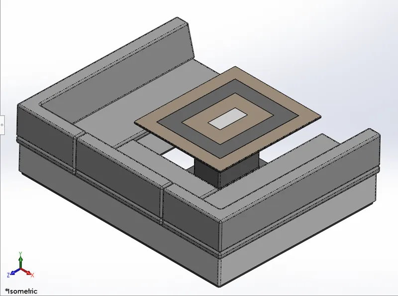
Features used to Create Middle Seat:
- Sketch
- Reference Plane
- Extrude Boss
- Fillet
- Chamfer
- Mirror
Propeller:
Propeller is rotating part gives forward and backward movements for Yacht by rotating in clockwise and anticlockwise directions. It is placing Down-backside of the Hull and is connected to the Engine.
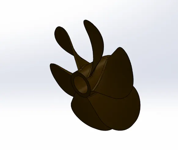
Features used to Create Propeller:
- Sketch
- Revolve Boss
- Reference Plane
- Lofted Boss
- Extrude Cut
- Circular Pattern
- Fillet
- Appearances
Lofted Boss:
The Loft feature allows you to generate complex geometry. It does this by interpolating Surfaces between various cross section of the model. These Cross sections can be sketches, faces or edges. In the Loft interface the cross sections are considered as loft profiles.
Circular Pattern:
This feature is used to create pattern of wings on Propeller shaft. The parent bodies/features are used to create number of instances required to create the pattern circularly.
Radar:
Radar is used to help navigate ships in fog and bad weather situations and used to detect other ships and land obstacles, to provide bearing and distance for collision avoidance and navigation at sea. It is mounted on Radar mast.
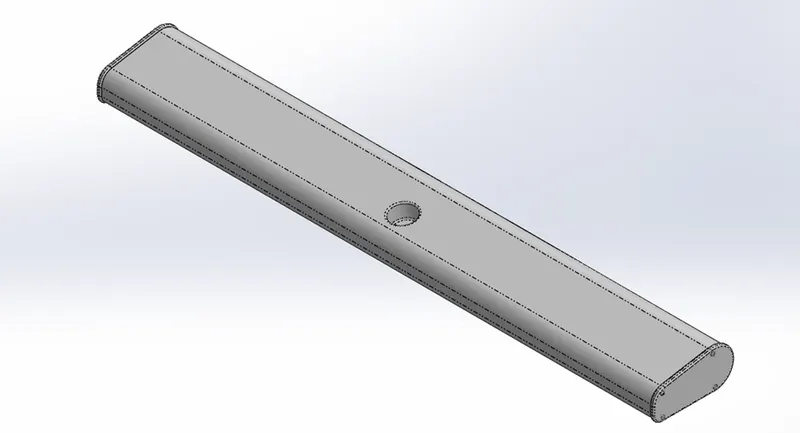
Features used to Create Radar:
- Sketch
- Extrude Boss
- Extrude Cut
- Sketch Pattern
- Split Line
- Fillet
- Mirror
Sketch Pattern:
The sketch pattern tool allows you to create patterns along a sketch.
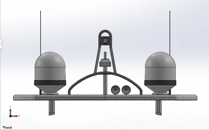
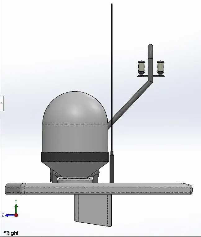
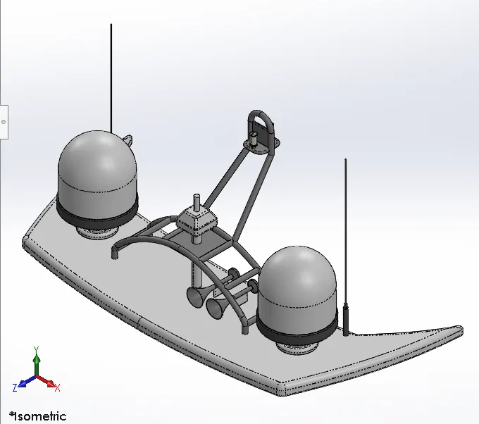
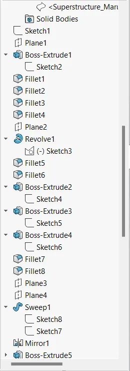
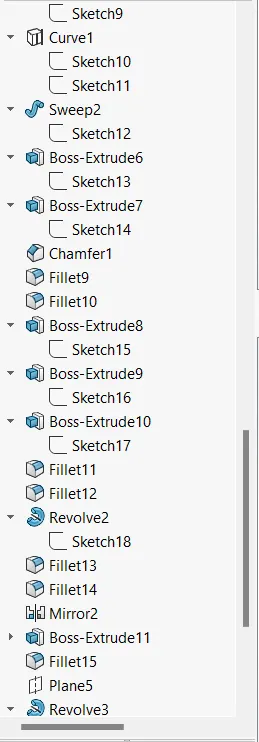
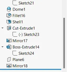
Radar Mast:
Radar mast placed on Top side of super structure. It has connections with Radar and Antennas.
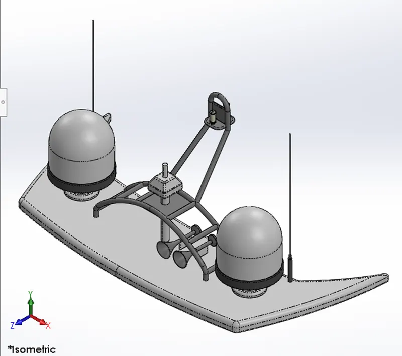
Features used to create Radar mast:
- Sketch
- Curve
- Extrude Boss
- Reference Plane
- Swept Boss
- Revolve Boss
- Dome
- Shell
- Fillet
- Chamfer
- Mirror
- Appearances
Rear Seat:
Rear seat is Placed Backside of super structure on Hull surface.
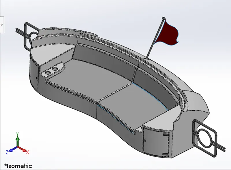
Features used to Create Rear Seat:
- Sketch
- Reference Plane
- Surface Extrude
- Swept Surface
- Lofted Surface
- Filled Surface
- Ruled Surface
- Offset Surface
- Extend Surface
- Trim Surface
- Knit Surface
- Extrude Boss
- Extrude Cut
- Revolve Boss
- Swept Boss
- Fillet
- Chamfer
- Mirror
- Appearances
Filled Surface:
The Filled Surface feature constructs a surface patch with any number of sides, within a boundary defined by existing model edges, sketches, or curves, including composite curves. You can use this feature to construct a surface to fill a gap in a model.
Ruled Surface:
Ruled Surfaces are surfaces that are generated using two curves with a straight line connecting each curve. The two driving curves can be 3D Curves or existing edges of parts or other surfaces.
Offset Surface:
The Surface offset command is used to create a surface, which is parallel to the original surface at a specified distance.
Extend Surface:
To mimic and continue the shape of the surface based on the vector of adjacent edges.
Super Structure:
Super Structure is placed on Hull Surface. Driving cabin and all control system is inside of superstructure. It has doors, windows, mirrors.
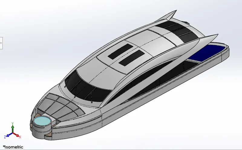
Features used to Create Super Structure:
- Sketch
- Curve
- Reference Plane
- Surface Extrude
- Swept Surface
- Lofted Surface
- Filled Surface
- Offset Surface
- Ruled Surface
- Delete Face
- Extend Surface
- Trim Surface
- Knit Surface
- Thicken
- Extrude Boss
- Swept Boss
- Extrude Cut
- Dome
- Fillet
- Split Line
- Chamfer
- Mirror
- Appearances
Thicken:
Converts a surface into a 3D solid with a specified thickness. Find. A useful technique for modelling a complex 3D curved solid is to first create a surface and then convert it to a 3D solid by thickening it.
Assembly Predator Yacht:
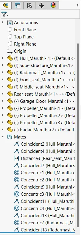
- Initially the Hull part is inserted in the assembly by using insert parts in the option. After that the part Is inserted in the assembly environment and click ok to fix the Hull.
- Super structure, Front seat, Middle Seat and Rear seat inserted and click OK to fix on the Hull surface automatically.
- After those other parts of the Predator Yacht are inserted into the assembly and given possible mate conditions.
- Camera View added.
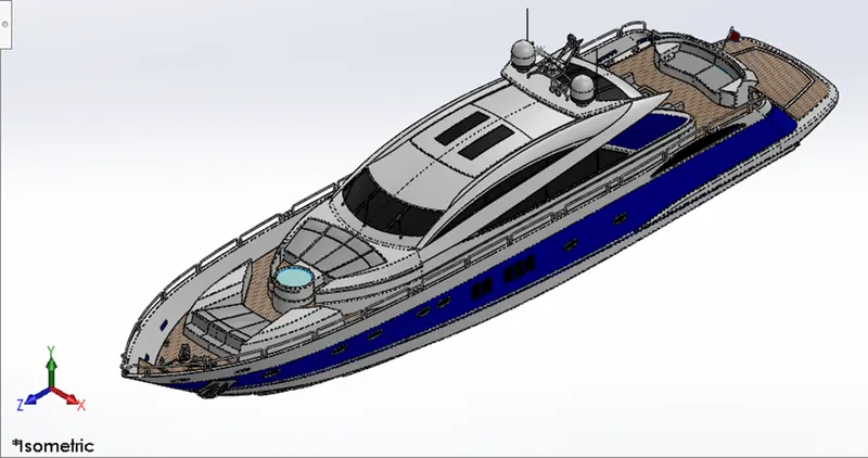
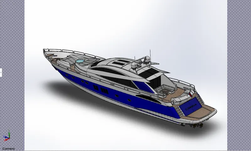
Features used in Assembly Predator Yacht:
- Inserting Parts
- Mates
Mates:
Mates create geometrical relationship between the assembly components. As we add mates, we define the allowable directions of linear or rotational motion of the components. We can move a component with in its degree of freedom, visualizing the assembly of behavior.
Conclusion:
- The Parts of Yacht are modelled.
- The Parts are inserted into the assembly environment and Yacht is assembled.
- The Camera View is Prepared.