Week 7 Challenge - Assembly Workbench
Week 7 Challenge - Assembly Workbench
Model drawing 1 - This assembly deals with the setup of Quick Return Mechanism which consists of total 5 models as shown in the below attached screenshot. These models are made in the 'part' workbench and then opened in the assembly workbench.
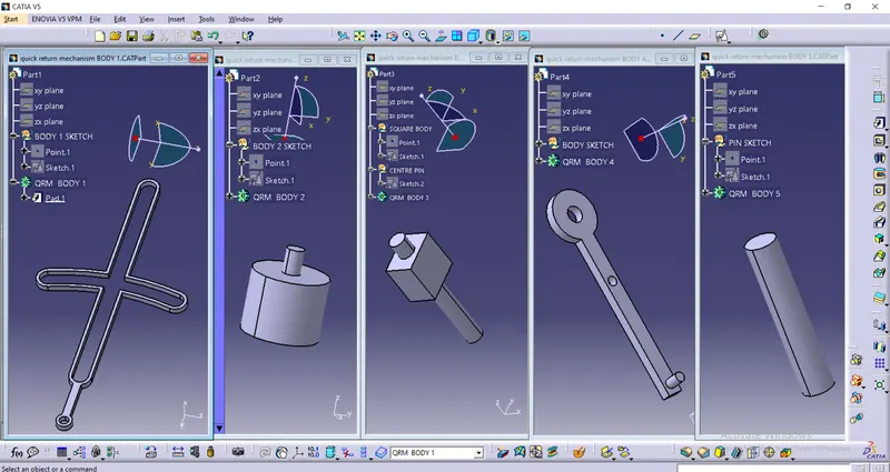
These models are then assembled together at their respective positions as shown in the below screenshot of Assembly.
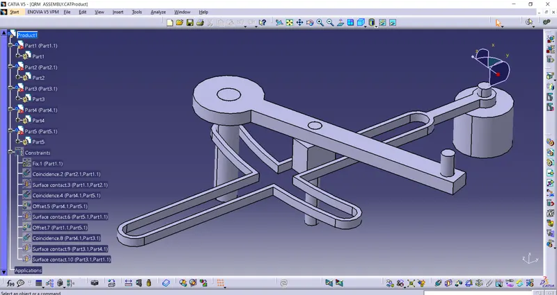
The above assembly is created by importing the existing part components and assembling them together. These 5 models are named as BODY 1, BODY 2, BODY 3, BODY 4, and BODY 5. After inporting models the BODY 1 is made fixed to its position.
Then BODY 2 is asembled to BODY 1 by using the 'coincidence constraint' (by selecting axis to be coincide) and 'contact constraint' ( by selecting the faces to be contacted). Then BODY 5 is assembled to BODY 4 by using the 'coincidence constraint' and 'offset cointraint' (making the faces at 0 distance).
Then BODY 3 is assembled to BODY 4 by using both coincidence & contact constraint.
Then these three assembled bodies (BODY 2, BODY 3, BODY4) are assembled to BODY 1 at the specific position using contact and offset constraints as shown in the above picture.
After assembly the Drafting sheets of the models and complete assembly are also created and those files are attached below.
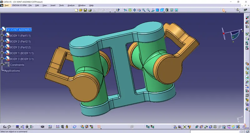
Model Drawing 2 - This assembly deals with the setup of CV JOINT ASSEMBLY which consists of total 3 models as shown in the below attached screenshot. In this assembly 2 out of 3 models are used twice for the completion of joint. These models are made in the 'part' workbench and then opened in the assembly workbench.
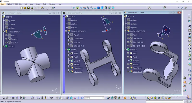
The drawing 2 consists of the assembly of CV JOINT which has total 3 parts that are BODY 1, BODY 2, and BODY 3. In the assembly BODY 1 and BODY 3 are imported twice to complete the assembly as shown below. To assemble the parts, first of all BODY 2 is made fixed and BODY 1 is assembled to the 1st and 2nd side of BODY 2 by using coincidence and contact constraints. Then BODY 3 is assembled to the open part of BOdY 1 at both the sides using coincidence and contact constraints. The below picture represents the complete assemble of CV JOINT. In the picture BODY 1 is represented by Green color, BODY 2 is represented by Blue color, and BODY 3 is represented by Brown color.