Week 7 Challenge
OBJECTIVE- CORE , CAVITY AND SLIDER CREATION FOR DOOR BEZEL USING SOLIDWORKS
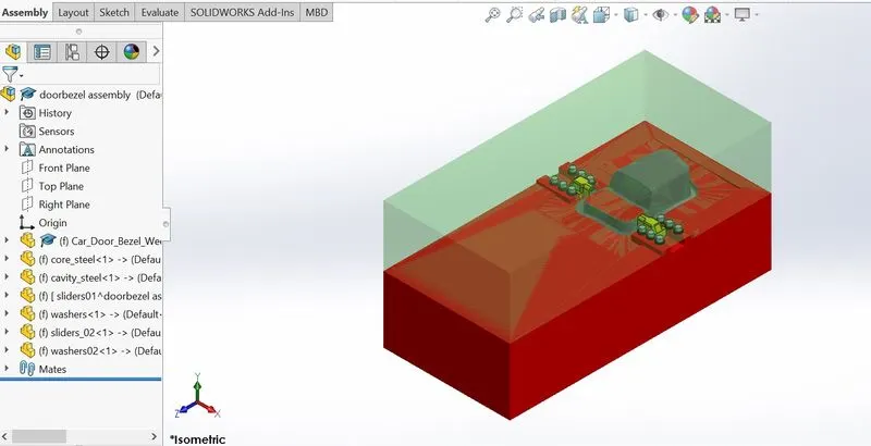
- In this project core, cavity blocks and slider for a car door bezel was created and assembled by following step by step process to attain best results.
- Bolt, Washer and locking mechanism were created and assembled for the sliders.
- Assuming the material for the model as ABS (shrinkage-0.6%), the scale value is determined as (0.6/100)+1=1.006 for the model.
STEPS-
The steps followed and commands used for core and cavity block creation are-
- mold pull direction
The direction in which the core moves apart from the model, bsed on the models and the features in the model the direction of pull is determined.
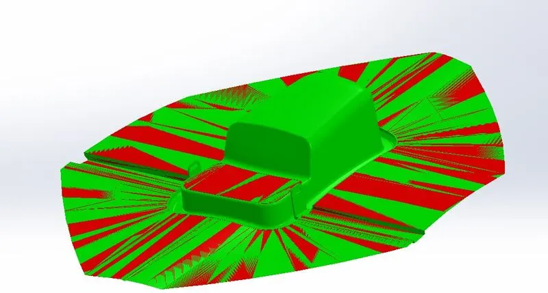
- Draft analysis
Analyse draft angles of face based on mold pull directions for moment of core and cavity. There should not be any zero draft angle genrally positive draft angle is on cavity side and negative draft angle is on core side.
- Scale
Scales the model by a specifed factor based on the material provide (shrinkage factor)
- Parting line
Parting lines and surface are created for seprating the core and cavity surface.
- Shutoff suurface
Create mold shut off surfaces, it prevents the flow of injected material by creating shut off surfaces.
- Parting surface
Create paerting surface between core and cavity blocks.
- Core and cavity blocks
The core and cavity blocks are created as individual part in asssembly by inserting the component as core and cavity surface created for car door bezel. The sprue location will be adjusted by rotating and giving mates with the planes of assembly.
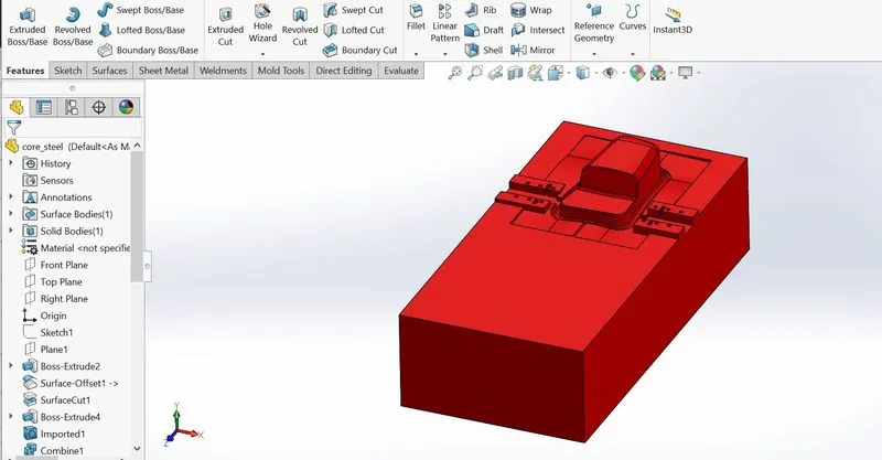
1.Core
The core block is created using the core surface created and there will be 2 blocks internal and external block which are created considering the minimum distance between mold and the outer edge and the base of slider these two blocks are due to a curvature in parting line and combinedly these two blocks acts as a single core block.
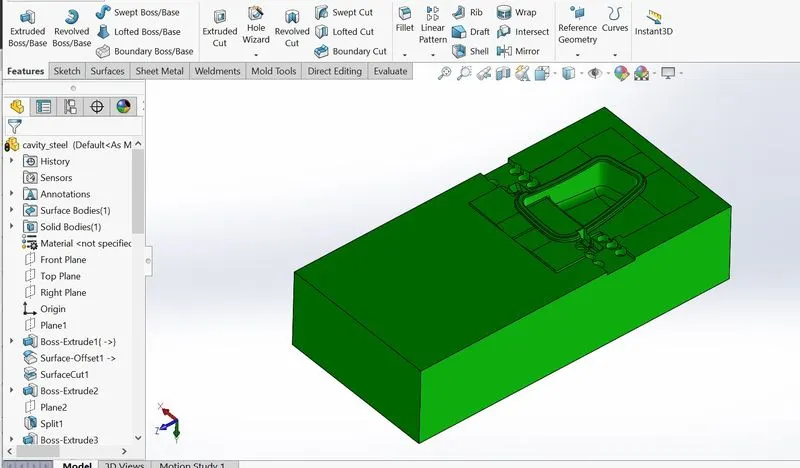
2.CAVITY
The cavity block is created using the cavity surface created and there will be 2 blocks and external block which are created considering the minimum distance between mold and the outer edge and the base of sliders these two blocks are due to a curvature in parting line and combinedly these two blocks as single cavity surface.
During mold design of car door bezel in the step of draft analysis we can clearly observe an undercut sliders will be used.
3.Sliders
Due to special requirements of a particular part may not be consistent with the mold opening direction of the injection molding machine ( product undercut ), the slider also known as slide , it is a mold mechanism that is developed to solve the issues with the undercut. The basic principle is to turn vertical movement of a mold opening/ closing into a horizontal motion. In order to cope with the situation that the undercut is located in the core or cavity, different structural forms are developed. During mold design of car door bezel in the step of draft analysis we can clearly observe an undercut sliders will be used.
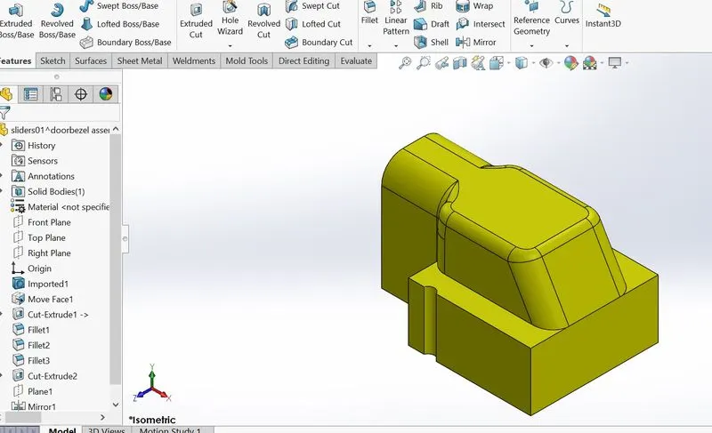
Slider direction will be perpendicular to the direction of the pull which will be horizontal these are separable from the core and cavity as the slider are movable , they should have base for the movement from the model we easily provide a base while creating the block itself, and the undercut will be the slots slider are designed in a manner that they will be able to close that slot with an extruded shape of the slot.
SLIDER CREATION
The commands used for creation of sliders are
- Reference plane- command used to create a plane, axis.
- Sketch- command used for creating sketch.
- Convert entities- it is a tool availaible in sketching to project the sketch selected.
- Split- it is a availaible in features tabs used to split the body in two pieces along the sketch based applications.
- Fillets- it is used to make fillets to edge of solid bodies.
- Cut extrude- it is used to remove material from a solid body along the sketchn in the direction needed.
- Extrude boss base- it is used to add material in desired directions.
- Move face- it is availaible in the mold tools tab used to move face of a solid body.
- Move/copy bodies- it is available in mold tools used to move , copies and rotate solid and surface bodies.
- Combine- it is availaible in mold tools used to add substract bodies.
4.Washers and bolts
They are designed besides the slider base for this separate space is assigned on the blocks while modifying the blocks after the slider design.
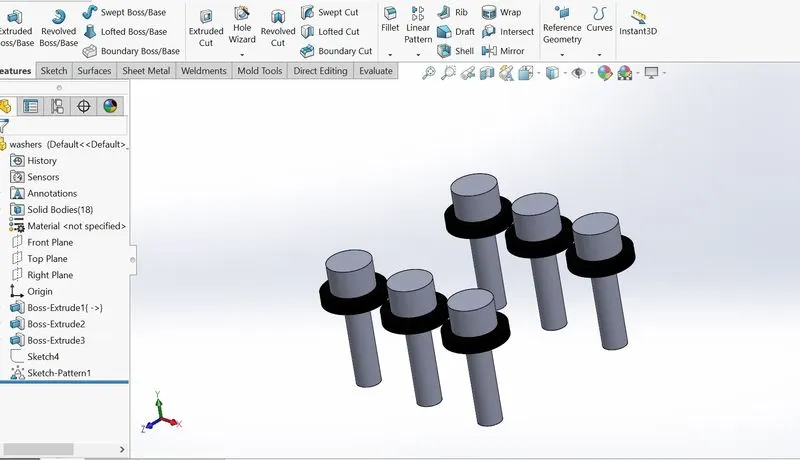
As the slider movement should be restricted , we should create a locking mechanism such that up to some distance only the slider can move for this certain space should be allocated in the cavity block that space will be designed considering the distance of travel of slider.
The final mold design with sliders and locking mechanism created will be
exploded view
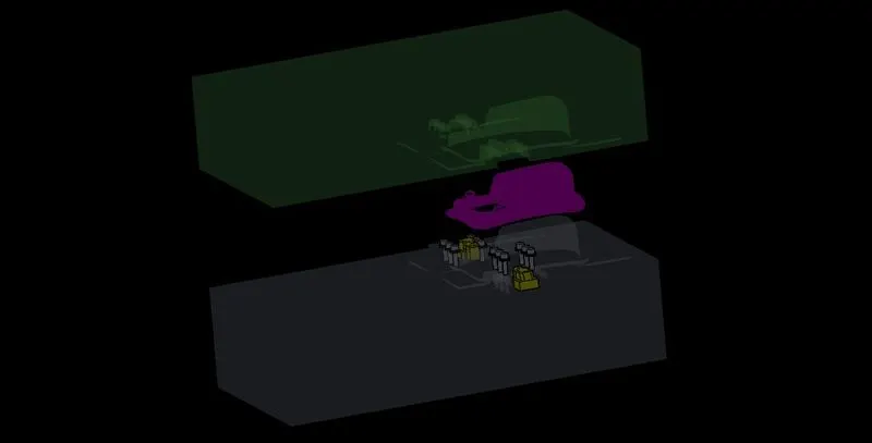
assembly
CONCLUSION- following parts were created and assembled with proper engineering constraints.
- CORE AND CAVITY SURFACE
- CORE BLOCK
- CAVITY BLOCK
- SLIDERS
- BOLTS AND WASHER
- LOCKING MECHANISM