Week 7 Challenge
Q. Load the vehicle parameters. Complete the vehicle model by modelling the remaining equations. Set simulation stop time to 598 sec.
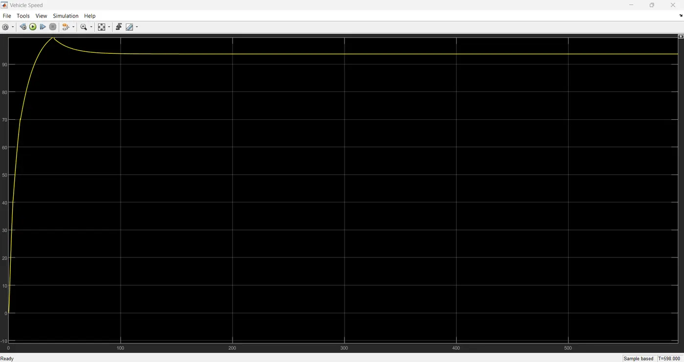
The output should be the vehicle velocity.
Solution:
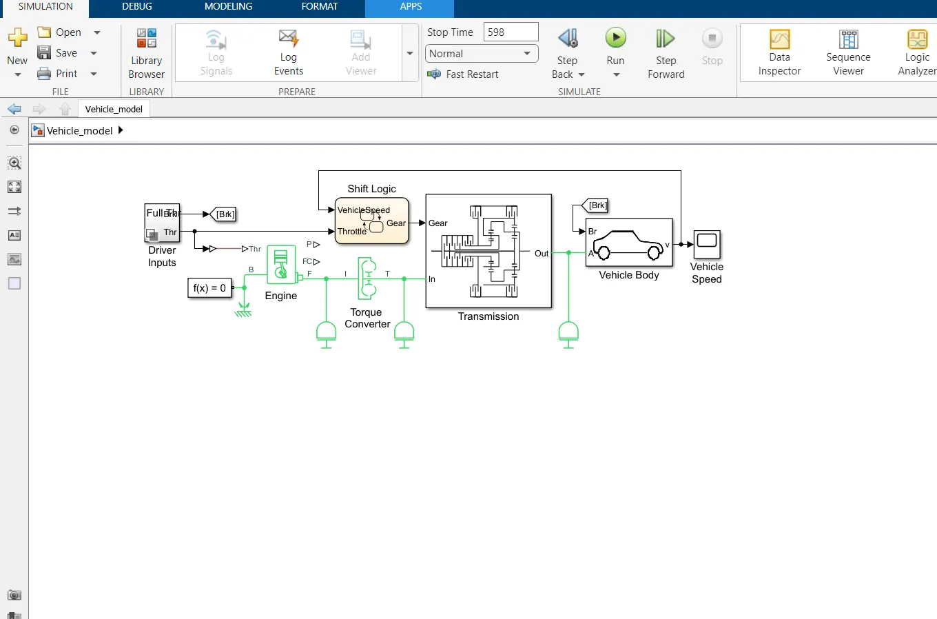
The main driveline subsystems and components are:
- Driver Inputs — Throttle/brake profile
- Engine — System-level model of spark-ignition and diesel engine
- Torque Converter — Three-part torque converter consisting of an impeller, a turbine, and a stator.
- Transmission subsystem — CR-CR 4-speed transmission
- Shift Logic — Stateflow implemented transmission controller
- Vehicle Body — Vehicle, tire, and brake dynamics
While the engine is idling initially at a nonzero speed, the transmission output and the vehicle as a whole are initially not moving.
Model the Throttle/Brake Profile
The Driver Inputs block is a subcomponent implementation that provides throttle and brake signals to the engine and transmission control system. Open the Driver Inputs block to view the throttle/brake profile for the simulation.
The throttle signal feeds to the engine and to the transmission controller.
The brake signal supplies the input force that actuates braking in a Double-Shoe Brake block in the Vehicle Body subsystem.
Model the Engine
For the purposes of system modeling, an engine or motor specifies an output torque as a function of driveline speed. The engine has a connection port coupling it rotationally to the rest of the system.
Using an Engine Block from Vehicle Components
The Engines library contains blocks that you control using an input physical signal for the throttle. You can parameterize the Generic Engine block using vectors to specify speed and torque. The block calculates the maximum possible torque as a function of the engine speed at any instant. The throttle signal controls how much of the maximum torque the engine can deliver. The Piston Engine block accounts for the instantaneous torque transmitted to the engine drive shaft. The instantaneous torque enables you to model vibrations in the drivetrain due to piston revolution. To model just the piston mechanism of a combustion engine, use the Piston block.
The Model uses a Generic Engine block, configured as spark-ignition type. The block properties specified in the property inspector include the maximum power, speed at maximum power, and maximum possible speed of the engine. To view engine settings, click the Engine block. The engine torque and motion are modeled relative to the rotational ground, which is taken as the base reference of the engine and the starting point of the driveline, or mechanical rotational, connections in this model.
Alternative and Advanced Methods for Modeling Engines
Simscape Driveline allows you to create complex, custom engine models. Several important engine features to consider in a complex model are:
- Distinguishing steady-state behavior from engine start-up, when the engine speed-engine torque function has not yet reached its maximum possible envelope
- Details of mechanical power production, such as air-fuel compression and combustion
- Additional controls beyond what can be represented by a single throttle signal
Model the Transmission
The CR-CR 4-speed transmission subsystem in the Model is similar to other examples with the same transmission. The clutch and planetary gear properties are set in the blocks with model workspace variables.
|
Workspace Variable |
Description |
|
eff_tor_rad |
Clutch: effective torque radius (m) |
|
num_fric_surf |
Clutch: number of friction surfaces in contact |
|
engagement_area |
Clutch: friction surface area in contact (m2) |
|
fric_coeff |
Clutch: kinetic friction coefficient of surfaces in contact |
|
peak_normal |
Clutch: static (locking) friction coefficient of surfaces in contact |
|
velTol |
Clutch: clutch velocity locking tolerance (rad/s) |
|
pressThresh |
Clutch: Normalized pressure threshold |
|
p0 |
Clutch: Physical pressure normalization (Pa) |
Couple the Engine to the Transmission
The Model couples the engine and the transmission through a torque converter block.
Torque Converter Stage
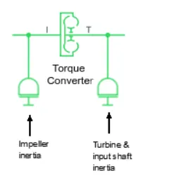
Like a clutch, a torque converter couples two independent driveline axes to transfer angular motion and torque from an input to an output shaft. However, unlike a clutch, a torque converter never locks. The torque converter transfers motion by hydrodynamic viscosity, not by surface friction. Thus a torque converter does not step through discrete stages and avoids the motion discontinuities inherent in friction clutches.
To mimic engine idling at the start of the simulation, the initial condition of the impeller inertia is a nonzero angular velocity. The initial condition of the turbine & input shaft inertia is zero speed.
Model the Tires, Brakes, Wheels, and Road
The transmission feeds its output torque to the final drive subsystem, Vehicle Body. This subsystem represents the vehicle inertia (the load on the transmission), the wheels, the brakes, the driving conditions, and the wheel contact with the road. The subsystem models only the rear wheels as driven by the transmission.
Final Drive Subsystem: Vehicle Body
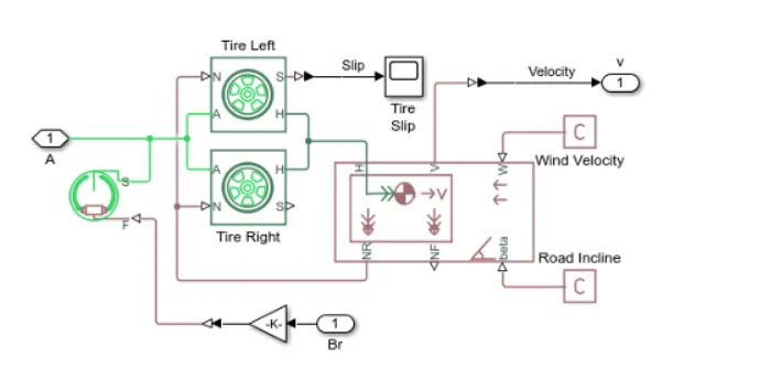
The subsystem has two major areas.
Modeling the Tires and Brakes
The right and left tire blocks accept the driveline torque and rotation from the transmission at their wheel axle rotational ports (A). Given a normal or vertical load (N), this torque and rotation are converted to a thrust force and translation at the wheel hub translational ports (H).
The tires rotate nonideally, slipping before they fully generate traction and react against the road surface. The tire slip of the left tire is reported as a physical signal and converted to Simulink® for use with the Tire slip scope.
The Double-Shoe Brake block represents a brake arranged as two pivoted rigid shoes that are symmetrically installed inside or outside of a drum and operated by one actuator. The brake block converts the braking signal from the Driver Inputs block to an actuator force that exerts a friction torque on the shaft that connects the brake drum to the tire blocks.
Modeling the Vehicle Body and Load
The driveline connection line sequence of the model ends with the Vehicle Body block, which specifies the vehicle geometry, mass, aerodynamic drag, and initial velocity (zero). This block generates the normal forces that the Tire blocks accept as vertical loads. Vehicle Body accepts the developed thrust force and motion at its horizontal motion translational port (H). The vehicle body model also accepts a wind velocity (W) and a road incline (beta), both provided by physical constants.
The rear wheel vertical load force (NR) is reported back to the Tire blocks. The forward wheel vertical load (NF) is not used.
The forward velocity (V) of the vehicle is converted and reported, through the subsystem outport, to the Vehicle velocity scope.
Alternative Differential, Wheel, Road, and Braking Models
The Model models only the rear wheels, the rear tires, and the vehicle body, without the more realistic drivetrain components of differential gears and brakes. The model illustrates how to model a vehicle that has four wheels and front and rear differential gears.
Control the Clutches
To select and engage the appropriate gear set, the model uses a Stateflow block and clutch schedule. To see how these components work, return to the main model of Model.
State-Controlled Gear Selection
The Stateflow block, which is labeled Shift Logic, implements gear selection for the transmission. The block determines whether to shift up or down based on input from two other components in the model. Driver Inputs block supplies throttle and braking information. The Vehicle Body subsystem supplies the velocity of the vehicle body via a feedback loop.
To open the Stateflow diagram, double-click the Shift Logic block. The Model Explorer is utilized to define the inputs as throttle and vehicle speed and the output as the desired gear number. Two dashed AND states keep track of the gear state and the state of the gear selection process. The overall chart is executed as a discrete-time system. The Stateflow diagram shown in the figure illustrates the functionality of the block.
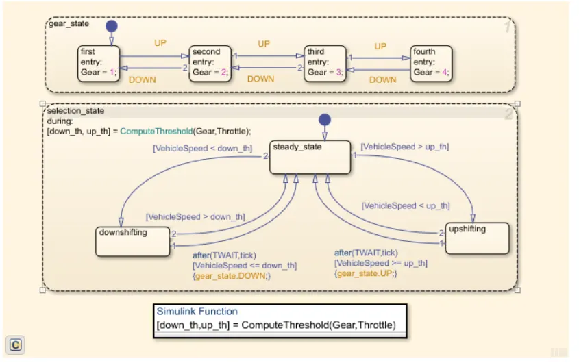
The model computes the upshifting and downshifting speed thresholds as a function of the instantaneous values of gear and throttle. While in steady_state, the model compares these values to the present vehicle speed to determine if a shift is required. If so, it enters one of the confirm states (upshifting or downshifting), which records the time of entry.
If the vehicle speed no longer satisfies the shift condition, while in the confirm state, the model ignores the shift and it transitions back to steady_state. The steady-state condition prevents extraneous shifts due to noise conditions. If the shift condition remains valid for a duration of TWAIT ticks, the model transitions through the lower junction and, depending on the current gear, it broadcasts one of the shift events. The model again activates steady_state after a transition through one of the central junctions. The shift event, which is broadcast to the gear_selection state, activates a transition to the appropriate new gear. The Stateflow block outputs the gear information to a clutch schedule subsystem that is in the transmission subsystem.
Clutch Schedule Subsystem
The signal from the Stateflow block to the clutch schedule controls the five clutches of the CR-CR 4-Speed transmission. To see the clutch schedule, open the Transmission subsystem, and then the Clutch Schedule subsystem.
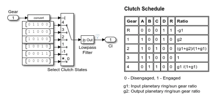
Now loading time as 598s
Result: