Week-6 Challenge: EV Drivetrain
Q.1:Which types of power converter circuits are employed in electric and hybrid electric vehicle?
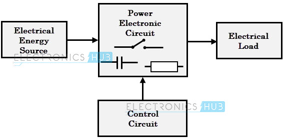
The block diagram of a power electronic converter is shown in figure above. It consist of an electrical energy source, power electronic circuit, a control circuit and an electric load. This converter changes one form of electrical energy to other form of electrical energy.
In the electric vehicle (EV) powertrain, all the electric input sources are connected to a HV–DC bus by an individual DC–DC converter, and the output three-phase electric motor (EM), i.e., the main load of the EV, is powered from this HV–DC bus through a three-phase inverter which drives the EM. Here, the voltage level of this HV–DC bus of the EV is around 400–750 V. Moreover, moving the EV via an EM from electric batteries, a DC–DC voltage is required because the batteries’ output voltage is much lower than the required voltage of EM. A traction inverter is needed to drive the EM by converting the DC batteries into variable-frequency AC.
DC to DC Converters
A DC chopper is a static device that converts a fixed input DC voltage to variable DC output or a fixed DC output of different magnitude (which can be lower or higher) than input value. The block diagram of a DC chopper is shown in figure below.
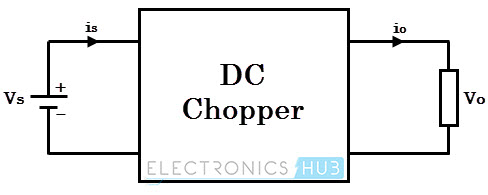
The chopper circuit is connected between DC input source and DC load. This chopper consists of power electronic switching devices such as thyristors which are connected in such a way that they produce required DC voltage to the load.
The output voltage is controlled by adjusting ON time of the thyristor (or switch) which turn changes the width of DC voltage pulse at the output. This method of switching is called as pulse width modulation (PWM) control.
The output of the chopper can be less or greater than the input and also it can be fixed or variable. These can be unidirectional or bidirectional devices based on the application it is intended for.
DC choppers are classified into three basic types based on input and output voltage levels and are discussed below.
Step-down Chopper or Buck converter
A step-down chopper produces an average output voltage lower than the input DC voltage. The circuit for this converter is shown in figure below.
Here the switching component is a thyristor that switches the input voltage to the load when it is triggered at particular instants.
A diode acts as a free wheeling diode that allows the load current to flow through it when thyristor is turned OFF. If this diode is absent, a high induced EMF in inductance may cause damage to the switching device.
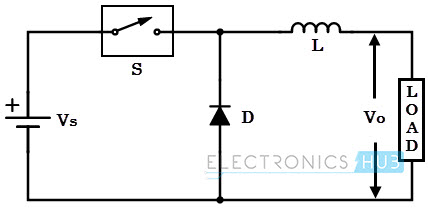
The average output voltage of the converter is varied by controlling turn ON/OFF periods of thyristor. When thyristor is turned ON, the output voltage is same as the input voltage and if it is turned OFF, the output voltage is zero.
The output voltage is equal to (TON / T) Vin. So, by controlling the duty ratio K = (TON / T), the output voltage will be increased.
Step-up Chopper or Boost converter
In this chopper, the output voltage is always greater than input voltage. The configuration of a boost converter is shown in figure below.
Here also a switch is used, which is connected in parallel with the load. This switch is a thyristor or an SCR.
As similar to the buck converter, a diode is placed in series with the load that allows the load current to flow when the thyristor is turned OFF.
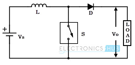
When the thyristor is turned ON, the diode is reverse-biased and hence it isolates the load circuit from the source. So the inductor charges to the maximum input voltage source.
When the thyristor is turned OFF, the load gets the voltage from input as well as from inductor. So the voltage appearing across the converter output will be more than the input.
Here the output voltage is equal to (1/ 1 – d) times the input voltage, where d is the duty ratio (TON / T). By varying this duty ratio, the output voltage will be varied till the load gets desired voltage.
Buck/Boost converter
This chopper can be used both in step-down and step-up modes by continuously adjusting its duty cycle. The configuration of buck-boost converter is shown in figure below that consists of only one switching device, i.e., one thyristor.
Along with an inductor and diode, additional capacitor is connected in parallel with this circuit.
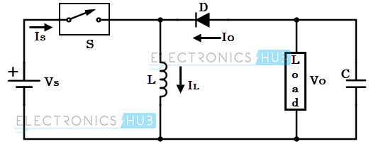
When the thyristor is turned ON, the supply current flows to the inductor through the thyristor and induces the voltage in inductor.
When the thyristor is OFF, the current in the inductor tends to decrease with the induced emf reversing polarity. The output voltage of this converter remains constant as capacitor is connected across the load.
By varying the value of duty ratio to a certain value, the output voltage is lower than the input voltage, typically in the range 0 ≥ k > 0.5, thus a buck converter.
And the output is higher than the input voltage if the duty ratio is in the range of 0.5 > K ≥ 1, thus acts as a boost converter.
AC to AC Converters
AC/AC converters connect an AC source to AC loads by controlling amount of power supplied to the load. This converter converts the AC voltage at one level to the other by varying its magnitude as well as frequency of the supply voltage.
AC/AC Voltage Converters
These converters control the rms value of output voltage at a constant frequency. The common application of these converters includes starting of AC motors and controlling power to heaters.
A single phase AC/AC voltage converter consists of a pair of anti-parallel thyristors along with a control circuit as shown in figure below.
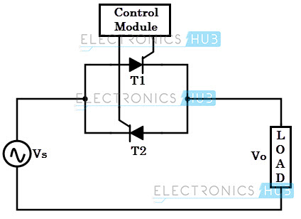
During positive half cycle of the input signal, thyristor-1 is forward biased and it starts conducting, when the triggering is applied. Thus the power flows from source to load.
In negative half cycle of the input, thyristor-2 is forward biased and starts conducting when it is triggered, while thyristor-1 is turned OFF by natural commutation.
By varying the triggering or conduction angel of each thyristor during each half-cycle, the magnitude of voltage appeared across the load is controlled.
The other popular form of AC voltage controller is the use of TRIAC in place of two anti-parallel thyristors. The figure below shows TRIAC based AC controller along with triggering control circuit.
Here diac controls the positive and negative triggering to the TRIAC so that average output voltage to the load is controlled.

DC to AC Converters or Inverters
These converters are connected between DC source of fixed input, and variable AC load. An inverter is a static device that converts fixed DC supply voltage to variable AC voltage.
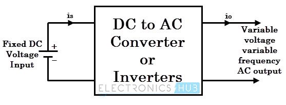
Here the fixed DC voltage is obtained from batteries or by DC link in most power electronic converter. The output of the inverter can be variable/ fixed AC voltage with variable/fixed frequency.
This conversion from DC to AC along with variable supply is produced by varying the triggering angle to the thyristors. Most of the thyristors used in inverters are employed with forced commutation technique.
These can be single phase or three phase inverter depending on the supply voltage. These converters are mainly divided into two groups. One is PWM based inverters and other multilevel inverters.
Further, these are classified voltage source inverter and current source inverter. Each type is subdivided into different types such as PWM, SVPWM, etc. Multilevel inverters are more popular in industrial applications.
The inverters overcome the drawbacks of PWM based inverters.
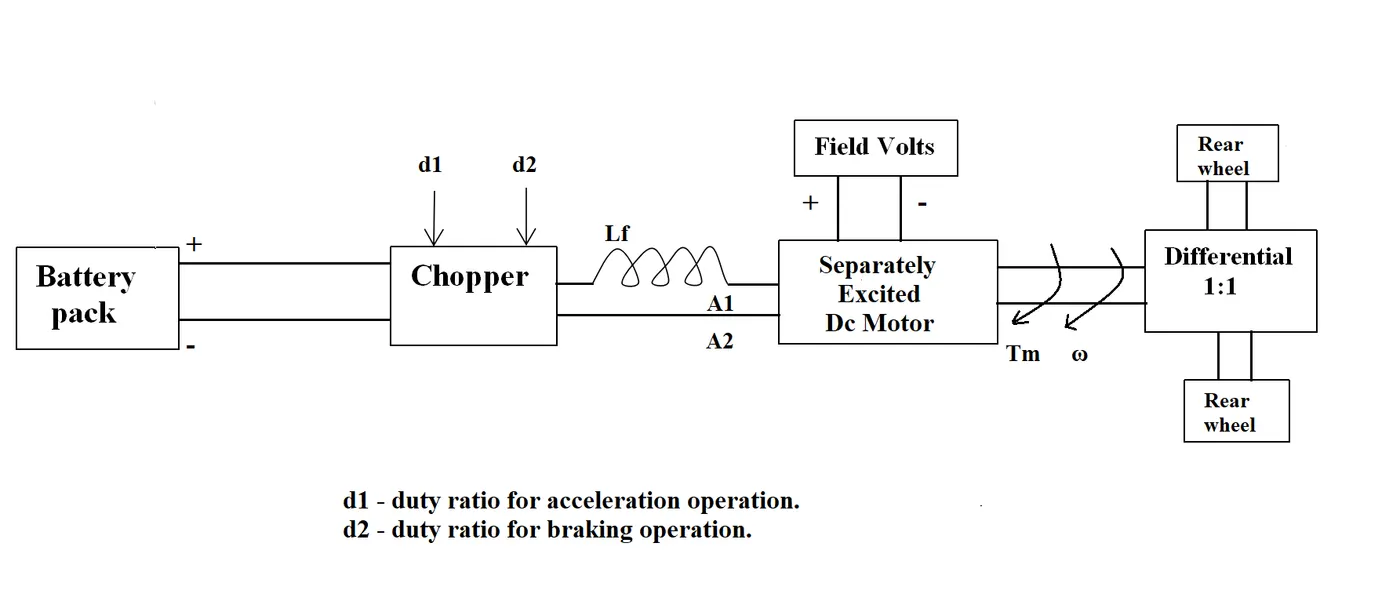
Q.2:An Electric Vehicle's powertrain with 72V battery pack in shown in the diagram below. The duty ratio for acceleration operation is 'd1' and for the braking operation the duty ratio is 'd2'.
The other parameters of the electric vehicle is given below,
Motor and Controller Parameters:
Rated Armature voltage= 72 V
Rated armature current= 400 A
Ra= 0.5Ω, KΦ= 0.7 Volt second
Chopper Switching frequency= 400 Hz
The vehicle speed-torque characteristics are given by the below equation

What is EV steady state speed if duty cycle is 70%?
Motor and Controller Parameters:
V= 72 V
I= 400 A
Ra= 0.5Ω, KΦ= 0.7 Volt second
Chopper Switching frequency= 400 Hz
The vehicle speed-torque characteristics are given by the below equation
Tv=24.7+0.0051 ω2 ------------- (1)
With duty cycle 70%, V=70%(72)=50.4V
Speed of motor
ω =(V/kϕ/Ra)-(Ra/(kϕ)2)T
T =(V*kϕ/Ra)-((kϕ)2*ω)/Ra)
T=((50.4*0.7)/0.5)-(0.72 * ω)/0.5
T=70.56-0.98 ω ------------ (2)
Equating equation (1) and(2),
24.7+0.0051 ω2 = 70.56-0.98 ω
0.0051 ω2+0.98 ω -45.86 =0
Solving the qudratic equation,
ω = 38.92 rad/s or -231.07 rad/s.
As speed cannot be negative, ω = 38.92 rad/s = 371.66 RPM.
Q.3:Develop a mathematical model of a DC Motor for the below equation using Simulink.
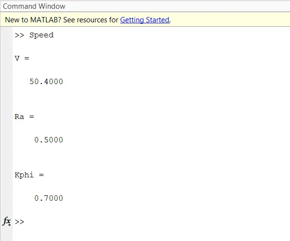
Considering the motor from above model,
Ra= 0.5Ω, KΦ= 0.7 Volt second
V=50.4V
INPUT:
SIMULINK MODEL:
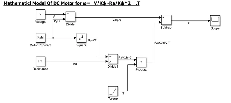
Blocks Used: Constant, Product, Divide, Subtract, Ramp, Mathematical Function(Square), Scope
Logic: The inputs are given by Constant Blocks - V, Kphi, Ra. The torque T is given by Ramp Block. The equation
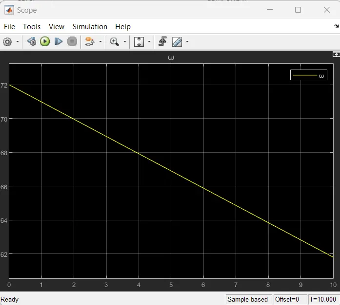
OUTPUT:
Q.4:Refer to the blog on below topic:
Induction Versus DC brushless motors by Wally Rippel, Tesla
Explain in brief about author’s perspective.
The blog Induction Versus DC brushless motors is by author Wally Rippel.
In the beginning author mentions the different types of engines that were and are available and discusses how best type of engine is not yet confirmed, rather, there are different types of engines to suit personal requirements, such as price and performance. This is also true for electric vehicle drives. Previously, there were lead acid batteries, DC brush motors, and contactor controllers. Today, Lead has been replaced by lithium and DC motor by either DC brushless motor or Induction Motor. Contactors are replaced by modulating inverters. He also quotes that there will be the future of both the technology (DC Brushless Motor and Induction Motor) depends upon their demands and uses.
Then he further discusses topics related to EV technology especially related to DC Brushless Motor and Induction Motor.
Brushless DC Motor: The rotor includes two or more permanent magnets that generate a DC magnetic field (as seen from the vantage point of the rotor). In turn, this magnetic field enters the stator core (a core made up of thin, stacked laminations) and interacts with currents flowing within the windings to produce a torque interaction between the rotor and stator. As the rotor rotates, it is necessary that the magnitude and polarity of the stator currents be continuously varied – and in just the right way - such that the torque remains constant and the conversion of electrical to mechanical energy is optimally efficient. The device that provides this current control is called an inverter. Without it, brushless motors are useless motors.
Induction motor: 3-phase induction motor was invented by Nikola Tesla. The stators for the 3-phase induction motor and the DC brushless motor are virtually identical. Both have three sets of “distributed windings” that are inserted within the stator core. The essential difference between the two machines is with the rotor.
Unlike the DC brushless rotor, the induction rotor has no magnets – just stacked steel laminations with buried peripheral conductors that form a “shorted structure.” Currents flowing in the stator windings produce a rotating magnetic field that enters the rotor. In turn, the frequency of this magnetic field as “seen” by the rotor is equal to the difference between the applied electrical frequency and the rotational “frequency” of the rotor itself. Accordingly, an induced voltage exists across the shorted structure that is proportionate to this speed difference between the rotor and electrical frequency. In response to this voltage, currents are produced within the rotor conductors that are approximately proportionate to the voltage, hence the speed difference. Finally, these currents interact with the original magnetic field to produce forces – a component of which is the desired rotor torque.
When a 3-phase induction motor is connected to utility type 3-phase power, torque is produced at the outset; the motor has the ability to start under load. No inverter is needed. The fact that induction motors are directly compatible with conventional utility power is the main reason for their success. In contrast, a brushless DC motor produces no starting torque when directly connected to fixed frequency utility power. They really need the aid of an inverter whose “phase” is maintained in step with the angular position of the rotor.
While 3-phase induction motors have great utility, they also have some severe limitations. They cannot operate from DC; AC is a must. Shaft speed is proportionate to line frequency. Hence, when used with utility power, they are constant speed machines. Finally, when operated from utility power, they have limited starting torque and somewhat limited running peak torque capabilities, when compared to DC type machines.
Author further discusses the advantages and disadvantages of both these motor drives.
Both DC brushless and induction drives use motors having similar stators. Both drives use 3-phase modulating inverters. The only differences are the rotors and the inverter controls. And with digital controllers, the only control differences are with control code. (DC brushless drives require an absolute position sensor, while induction drives require only a speed sensor; these differences are relatively small.)
One of the main differences is that much less rotor heat is generated with the DC brushless drive. Rotor cooling is easier and peak point efficiency is generally higher for this drive. The DC brushless drive can also operate at unity power factor, whereas the best power factor for the induction drive is about 85 percent. This means that the peak point energy efficiency for a DC brushless drive will typically be a few percentage points higher than for an induction drive.
In an ideal brushless drive, the strength of the magnetic field produced by the permanent magnets would be adjustable. When maximum torque is required, especially at low speeds, the magnetic field strength (B) should be maximum – so that inverter and motor currents are maintained at their lowest possible values. Unfortunately, there is no easy way of changing B with permanent magnets.
In contrast, induction machines have no magnets and B fields are “adjustable,” Thus, the induction machine when operated with a smart inverter has an advantage over a DC brushless machine – magnetic and conduction losses can be traded such that efficiency is optimized. This advantage becomes increasingly important as performance is increased. With DC brushless, as machine size grows, the magnetic losses increase proportionately and part load efficiency drops. With induction, as machine size grows, losses do not necessarily grow. Thus, induction drives may be the favored approach where high-performance is desired; peak efficiency will be a little less than with DC brushless, but average efficiency may actually be better.
Author also mentions that the Permanent magnets are expensive. Permanent magnet (PM) rotors are also difficult to handle due to very large forces that come into play when anything ferromagnetic gets close to them. This means that induction motors will likely retain a cost advantage over PM machines. Also, due to the field weakening capabilities of induction machines, inverter ratings and costs appear to be lower, especially for high performance drives. Since spinning induction machines produce little or no voltage when de-excited, they are easier to protect.
Author further confirms that Induction machines are more difficult to control. The control laws are more complex and difficult to understand. Achieving stability over the entire torque-speed range and over temperature is more difficult with induction than with DC brushless. This means added development costs, but likely little or no recurring costs.
Finally Author concludes that DC brushless drives will likely continue to dominate in the hybrid and coming plug-in hybrid markets, and that induction drives will likely maintain dominance for the high-performance pure electrics. He also questions what will happen as hybrids become more electrically intensive and as their performance levels increase? He finally concludes by saying The fact that so much of the hardware is common for both drives could mean that we will see induction and DC brushless live and work side by side during the coming golden era of hybrid and electric vehicles.