Project - Position control of mass spring damper system
Position control of mass spring damper system:
The governing equation for Spring-Mass-Damper (SMD) system is
F=mx_dot_dot+cx_dot+kx
where
m=mass
c=damping coefficient
k=spring constant
x_dot_dot=acceleration
x_dot=Velocity
x=Position
The Laplace Transorm is
F(s)=ms^2X(s)+csX(s)+k(s)=(ms^2+cs+k)X(s)
The transfer function can be written as X(s)/F(s)=1/ms^2+cs+k
The PID control design
The output of a PID controller, which is equal to the control input to the plant, is calculated in the time domain from the feedback error as follows:
u(t)=Kpe(t)+Ki*integral(e(t)dt)+Kd(de/dt)
The Laplace Transform gives us
Kp+Ki/s+Kds where Kp = proportional gain, Ki = integral gain, and kd = derivative gain.
We have considered wn=6.28rad/s (from fn=1 Hz)
zeta=0.9
The parameters given are
m = 3.6; %kg
k = 400; %N/m
c = 100; %Ns/m
The matrices are defined as
A=[0 1; -k/m -c/m]
B=[0; 1/m]
We find the poles of the function using MATLAB command
p1=(-zeta*wn)+(wn*sqrt((zeta^2)-1));
p2=(-zeta*wn)-(wn*sqrt((zeta^2)-1));
P=[p1, p2];
We find the value of K using
K=place(A,B,P);
Initially Kp and Kd are taken from K.
Blocks Used:
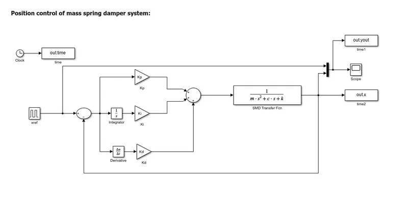
Clock, To Workspace, Pulse generator, Gain, Sum, Integrator, Derivative, Transfer Function, Scope.
Logic:
Input of Pulse Generator with value 1 for every 5 seconds is fed to PID control design with feedback input with sum block. PID control fdesign consists of gain blocks multiplied with integrator block and derivative block to get Kp, Ki and Kd gains. The output is fed to Transfer function block with value 1/ms^2+cs+k.The output also acts as feedback input.
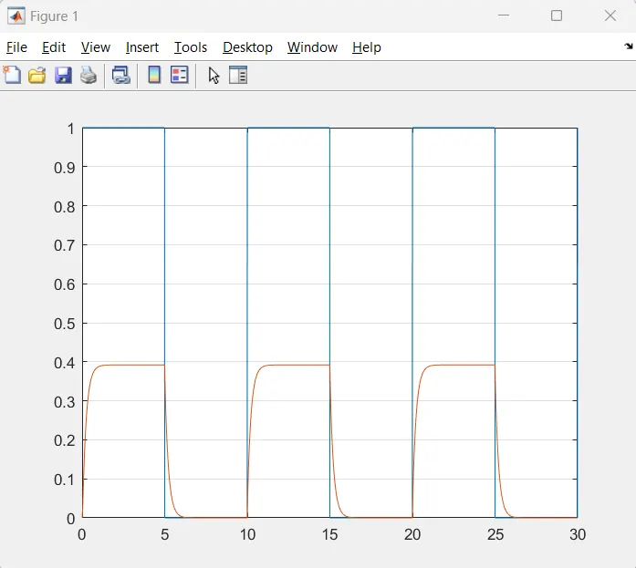
Output is diaplayed via Scope. Graph can be plotted using MATLAB command plot(out.time,out.x);
Simulink Model:
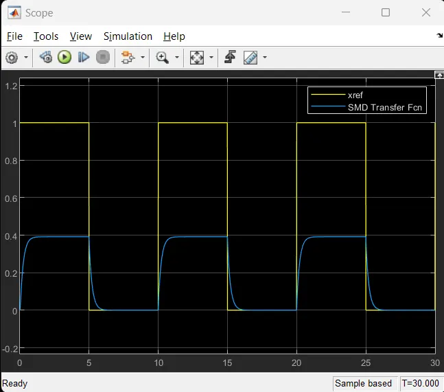
OUTPUT:
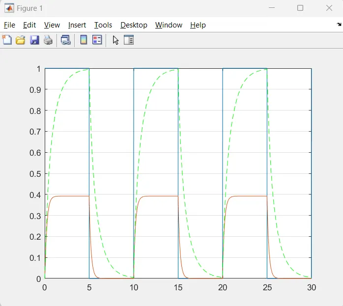
Kp=257.8777; Kd=59.2850;Ki=0;
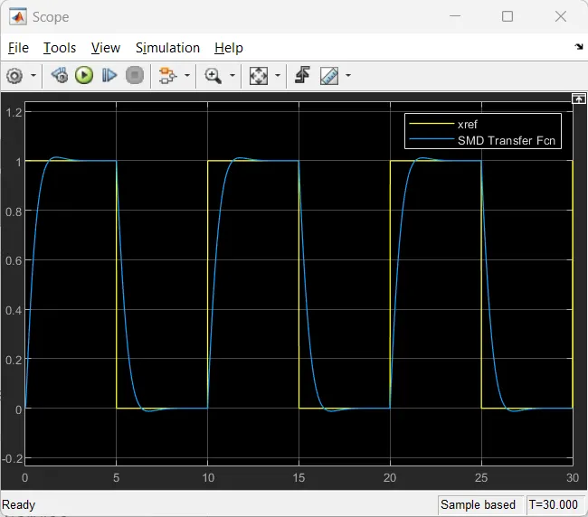
When Ki=500;
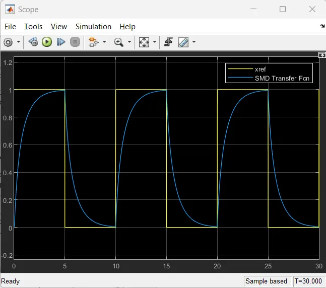
When Ki=1000;
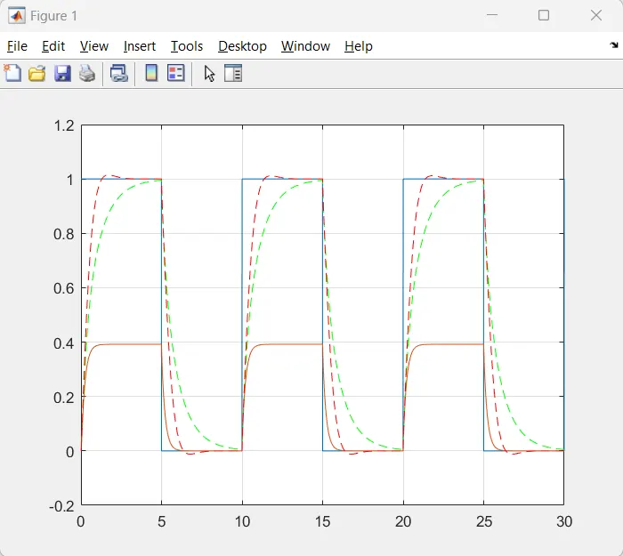
When Kd=25;Kp=300; Ki=2000;
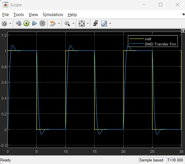
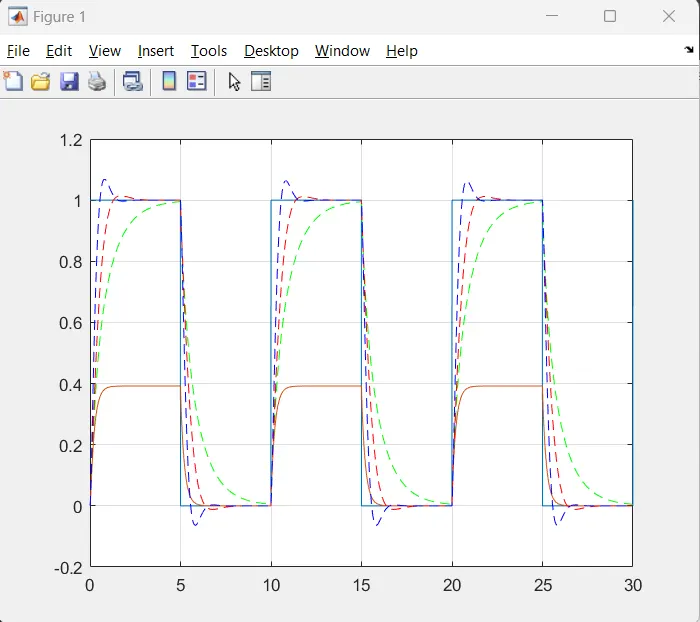
When Kd=10;
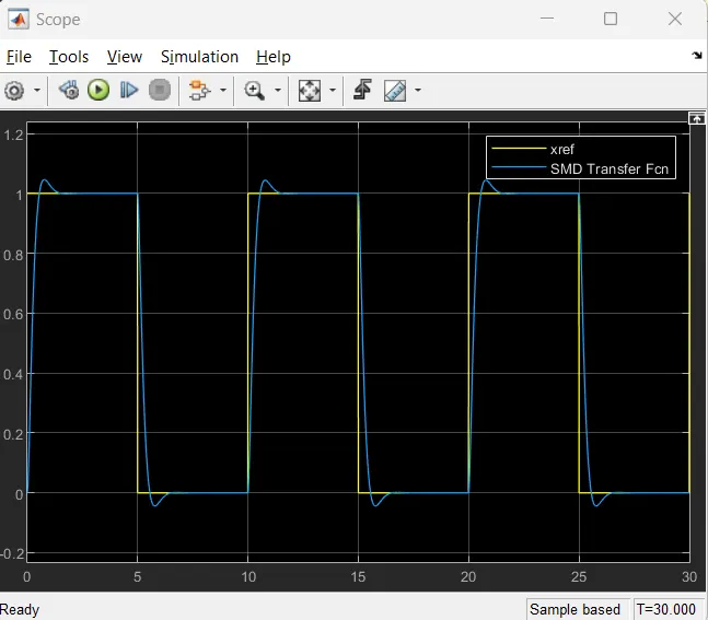
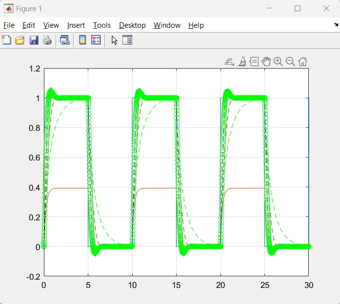
When Kd=10;Kp=400; Ki=2000;
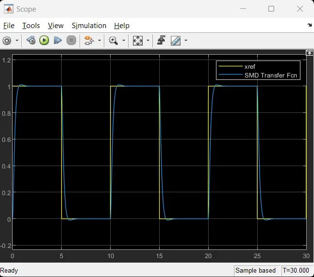
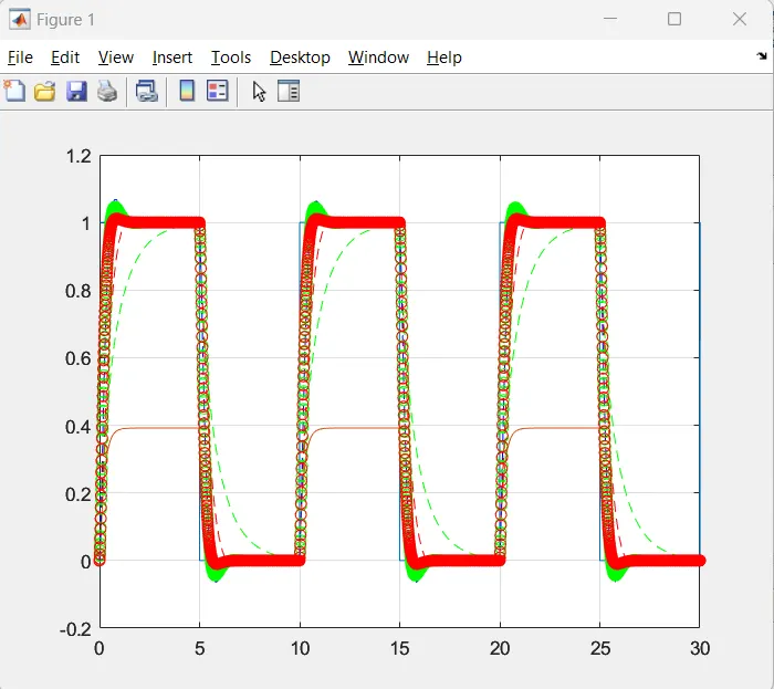
Hence Kd=10;Kp=400; Ki=2000; can be considered.