Week 7 Challenge
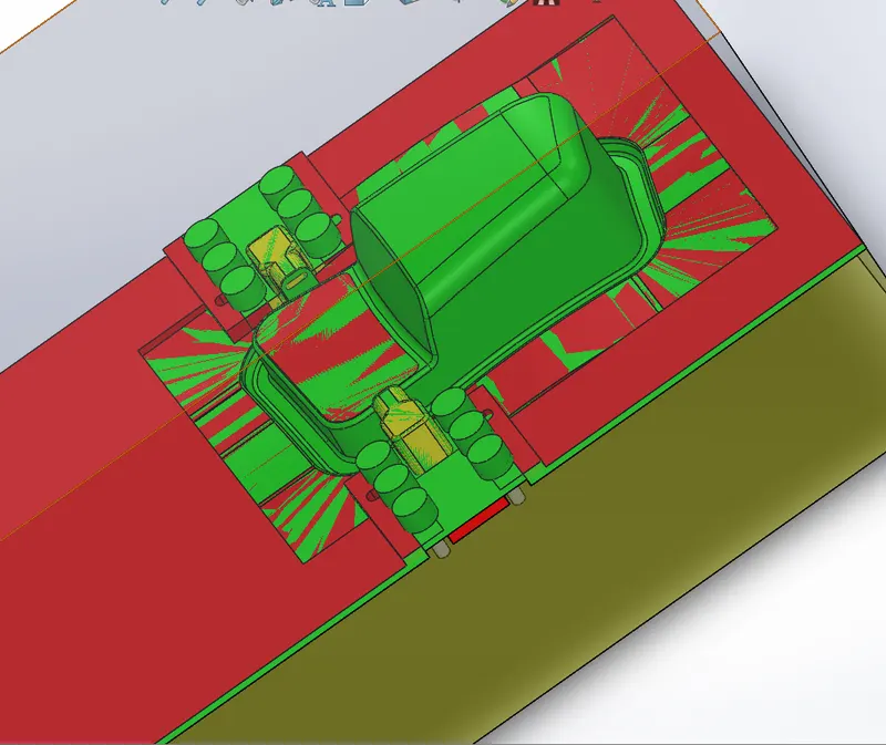
AIM: To create 2 sliders for the 2 undercuts present in the model
STAGES: create parts in the following order
- core and cavity surfaces
- core block
- cavity block
- sliders
- bolts and washers
- locking mechanism cut
PROCEDURE :
ASSEMBLY: In top-down assembly design, one or more features of a part are defined by something in an assembly, such as a layout sketch or the geometry of another part. The design intent comes from the top, which is the assembly and moves down to the parts.
first, we will import our car door bezel and create the necessary core and cavity
then we will create another component and name it as core_steel and then create the core block using the below methods
then we will create another component and name it as cavity steel and then create cavity block using the below method
- draft: (since we cannot change the draft angles for the given component without consulting with the designing team and can only ask them to make required changes but for this example, we are going to add drafts to this model ). A draft angle of 1½ to 2 degrees is required for most parts. This rule of thumb applies to parts with mold depths of up to 2 inches. At this size, a draft as low as 1½ degrees will allow for an easy, non-damaging release from the mold when the expected shrinkage of the thermoplastic material occurs.
- scaling factor: When you create a mold you must account for the scaling factor. The scaling factor is the amount the material in the mold shrinks or expands as it solidifies. The scaling factor depends on the type of material used and the shape of the mold and is expressed as a percentage of the linear size (not volume) of the design part.
The software scales the cavity by the specified scaling factor, using this formula:
Cavity size = part size * (1 + scaling factor/100)
- parting line and parting surface: It is a line that splits the mold into two parts – the core and the cavity. The concept of a parting surface is similar. A parting surface is a surface that separates the mold block into two parts – the core and the cavity. the blue line represents a parting line
- core: Core is an extended or male portion of the mold that creates the internal plastic part surface. Cores are used to get the internal cavity in the castings. Cores are placed into the mold after the removal of the casting. These are made up of sand are used in permanent molds also. The cores are surrounded by molten metal and therefore subjected to severe thermal and mechanical conditions
- cavity: The cavity is the female part that forms the external shape of the molding.
- split lines: lines are created in order to break the curves so that we can easily use ruled surfaces to extrude the edges where we want to
- boss extrude: Extrude tool is used to extend a sketched profile in one or two directions as either a thin feature or a solid feature.
- surface cut: we can cut a solid model by removing material with a surface or plane.
- direct editing : Direct Editing tab includes many tools that allow you to make changes to parts without modifying the existing sketches and features
- sketch driven pattern: Using sketch points within a sketch, you can specify a feature pattern. The seed feature propagates throughout the pattern to each point in the sketch.
- combine: The common function allows you to add or subtract two bodies together, and keep the area that is common to them. To use this feature, we will select the common button, and then under Bodies to Combine, select the two bodies.
- mates: Mates create geometric relationships between assembly components. As you add mates, you define the allowable directions of linear or rotational motion of the components. here we use mates so that we can bring the origin point over the sprue path
important notes:
- The reason for the distance between slider block and component is that it should be big enough so that it won't interfere with another component
- width: there will be a finger cap bit which will be inserted into it
- dia of a standard finger cap is 16mm so the width should be big enough to accommodate the finger cap
- 2/3 should be the length (approx)
- after creating 2 slider blocks use the combine function and subtract them from the core block
- create guide rails on the cavity block
- guide rails help to move the slider block back and forth
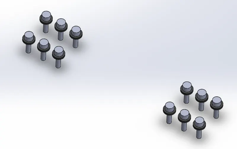
- washer and bolts: The primary purpose of most washers is to evenly distribute the load of the threaded fastener with which they are used. since in the industry, we would get accurate dimensions for making it will get a premade one, but for the practice we are going to make one by ourselves
- holes are created according to standard dimensions
screenshots
core surface
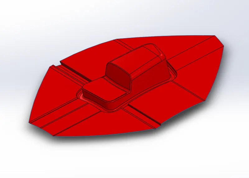
cavity surface
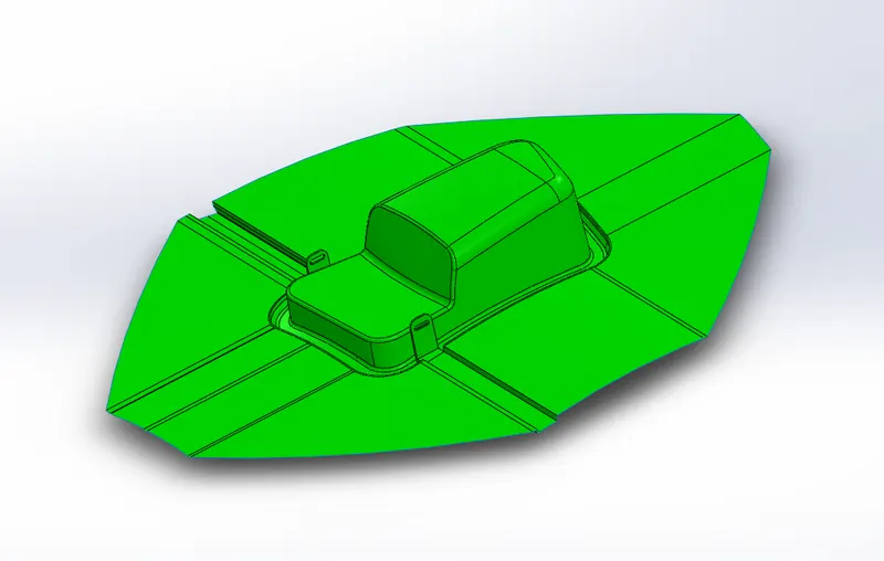
core block with holes and locking key slot
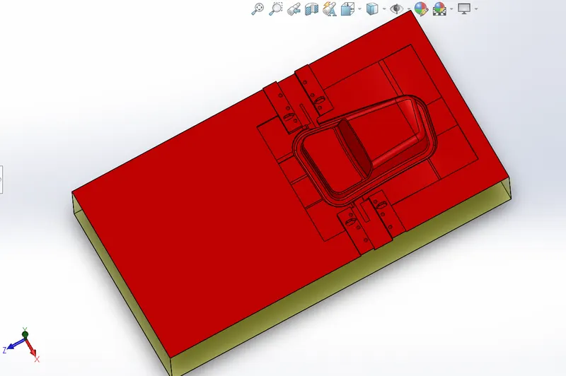
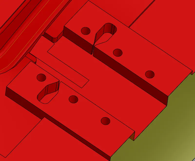
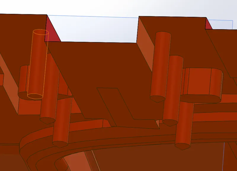
cavity block with tolerance holes
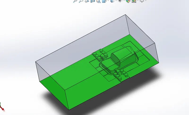
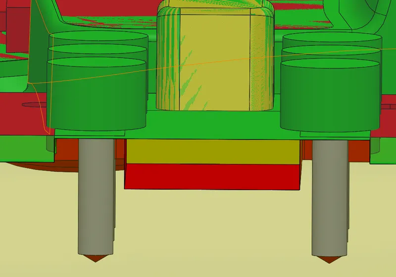
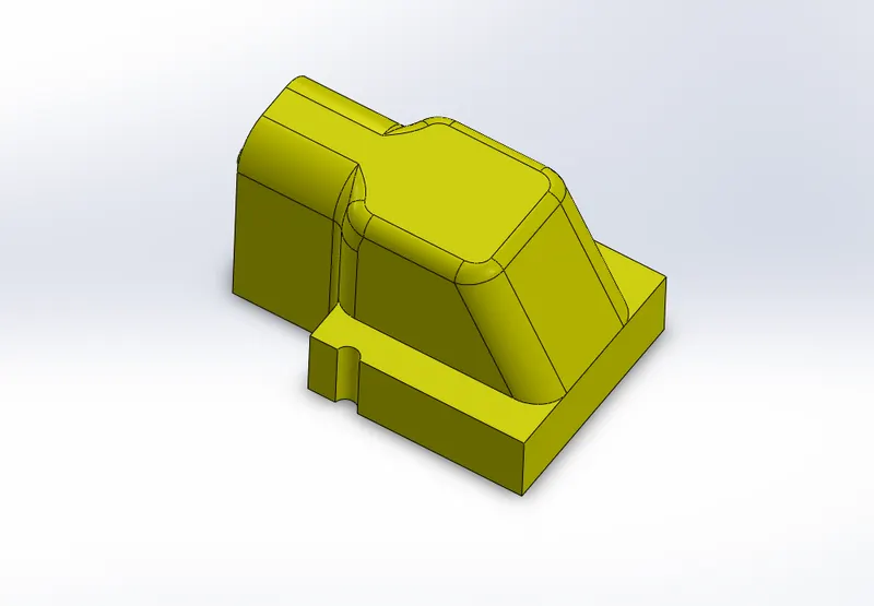
slider block with locking slot
washers and bolts