Week 7 Challenge
Aim:
To develop a mathematical model of vehicle using all the resisitve forces acting on the vehicle given the parameters of the various forces are provided.
Objective:
To output the vehicle velocity which is equal to the desired velocity (usually a drive cycle).
Theory:
- Forces acting opposite to the traction of the vehicle are Areo dynamic force, rolling resistance force, Grade angle force.
- Aerodynamic force:
Force imparted on the vehicle by the air around the vehicle is the areodynamic force. represented as follows
`F_(aero)=1/2**rho**C_d**A_f**V^2`
`rho= air density`
C-d = coefficient of drag
A_f= frontal area of the vehicle
V= velocity of the vehicle - Rolling resistance force:
Force on the vehicle caused due to the friction between road and tyres of the vehicle. Represented as follows
`F_(roll)=M**g**mu_(rr)**cos(theta)`
M - mass of the vehicle
`mu_(rr)`- coefficient of rolling resistance
`theta`-inclination of road
g- acceleration due to gravity - Grade angle force:
Force acting on the vehicle when it is moving on the inclined road. Represented as follows
`F_(gr)=M**g**sin(theta)`
Mathematical model using SIMULINK:
All the parameters required for vehicle modelling are entered into base workspace by running a VEH_Data.mat file in the command window.
Input is the US06 drive cycle which has a duration of 598 sec, so set the stop time of simulation to 598 sec.
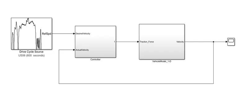
Controller:
Reduces the error between desired velocity and actual velocity. The error between the desired and actual velocity is fed to a PI controller where it reduces the error by given the required tractive force to the vehicle to overcome the resistive forces. So the out put of the controller is Tractive force.
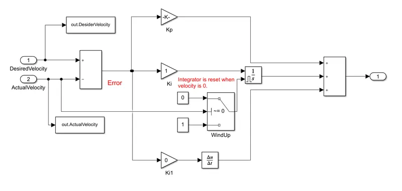
Intergral part of the controller is set with the anti windup facility where the intergrator is stopped from accumulating the error which result in the overshoots in the response. So integrator is reset whenever the velocity reaches 0.
Vehicle model: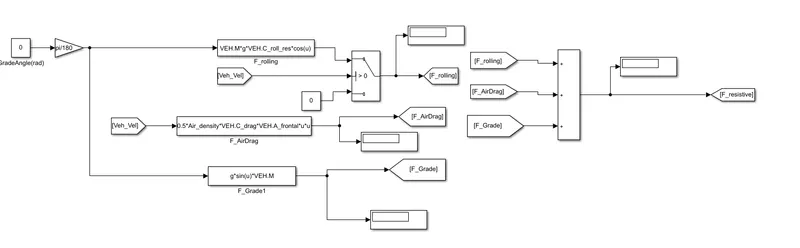
All the resistive forces are model using function blocks where the formulas for various force are written using the variables which are defined in the base workspace.
All the resistive forces are summed up and substracted from the tractive force(output of controller). The differnce between tractive and resistive results in acceleration of the vehicle.
Acceleration integrated upon time given the velocity of the vehicle. This velocity itself is used to calculat the resistive forces.

Result:
Actual velocity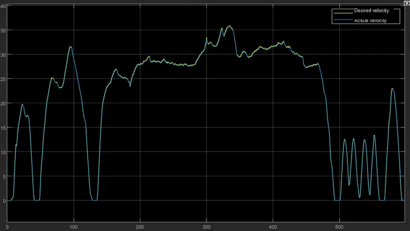
Actual velocity and desired velocity are almost overlapping each other.