Week 7 Challenge
AIM AND INTRODUCTION:
To calculate the water current forces for the bridge structure and apply the calculated loads in the Staad pro.
GIVEN DATA:
- The high flood level is 2 m above the foundation level.
- The span of the bridge is 45m.
- The mean velocity of the river is 3 m/s.
Water Current Forces:
An ocean current is a continuous, directed movement of sea water generated by a number of forces acting upon the water, including wind, the Coriolis effect, breaking waves, cabbeling, and temperature and salinity differences.
PROCEDURE:
To calculate the Water Current Forces;
Mean Velocity,Vmean=3m/s
Max.Velocity,V=√2*Vmean
=√2*3
=4.24m/s
Water Current,P=52*K*V^2
I have assumed the pier is circular, therefore K=0.66
∴Water Current,P=617.76KN/m^2.
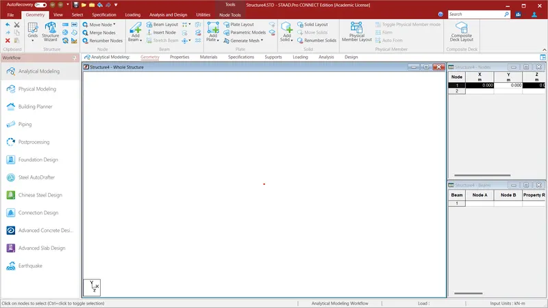
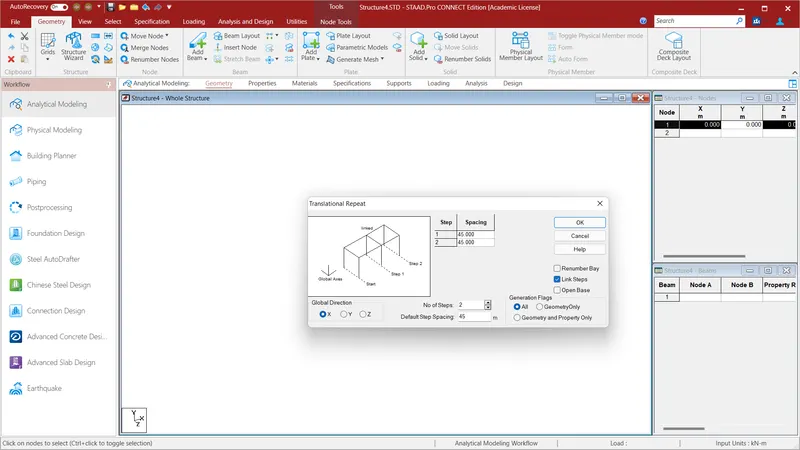
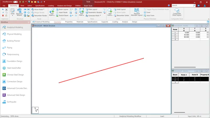
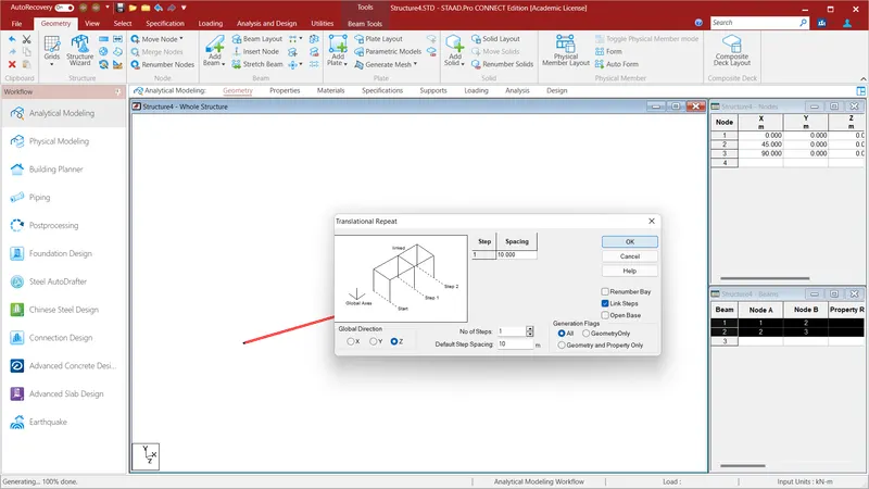
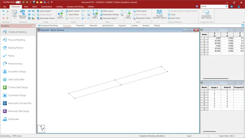
Create a node by creating the values of X=0;Y=0;Z=0 . Select the node using node cursor in the select option and go to Geometry option and select Translatyional Repeat and in Global X Direction by assigning the No.of Steps=2;Default Step Spacing=45m and click Link Steps and click OK. Again go to Geometry option and select Translatyional Repeat and in Global Z Direction by assigning the No.of Steps=1;Default Step Spacing=10m and click Link Steps and click OK.A Bridge of Length 90m and width of 10m will be created.
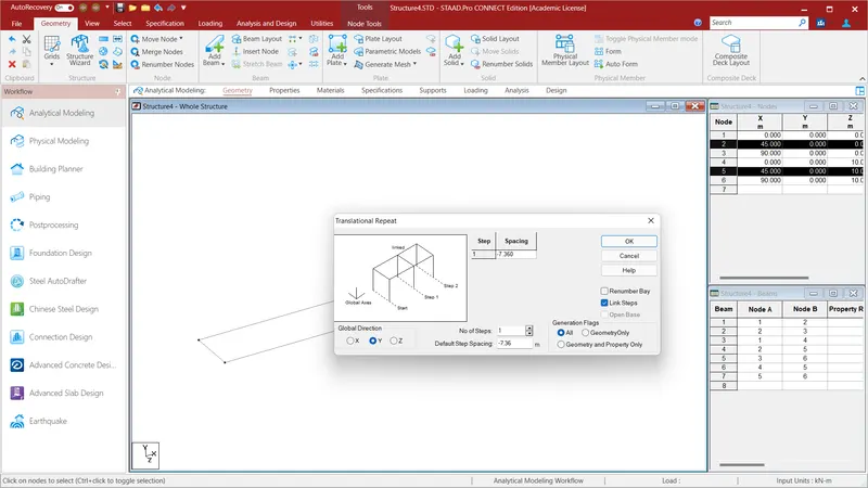
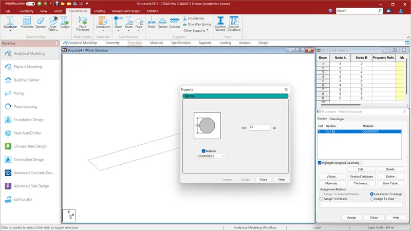
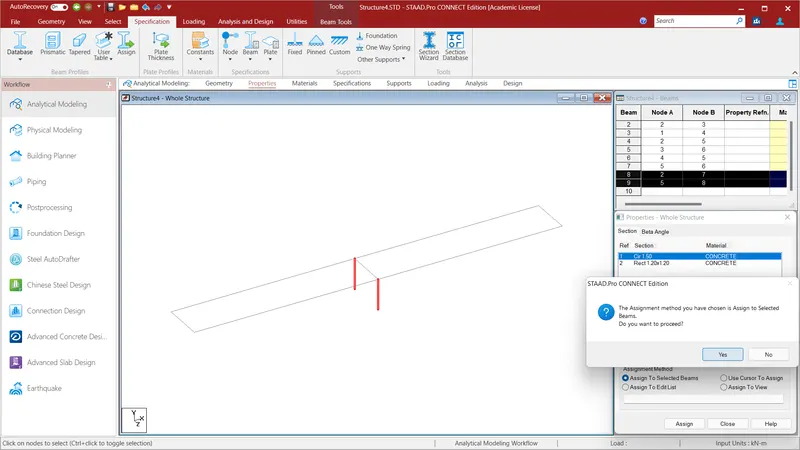
Go to Geometry option and select Translatyional Repeat and in Global Y Direction by assigning the No.of Steps=1;Default Step Spacing=-7.36m and click Link Steps and click OK.{I have assumed the height from the Foundation to Riverbed as 2m i,e.,5.36+2=7.36m}.A pier of Height 7.36 will be created at the 45m length. Now we shall assign properties to the Pier. Go to Specification Option and select Prismatic Option and select the Circle and give the values of YD=1.5m by using Concrete Material and click ADD. Now select the Piers and give Assign to Selected Beams and Assign and click ADD and YES. The properties to the piers will be assigned.
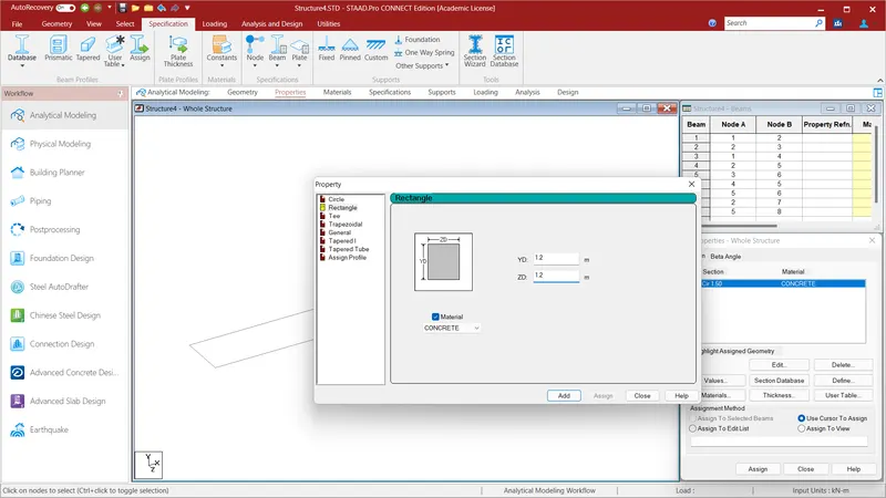
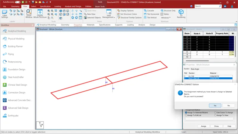
Now we have assign properties to the beams.Go to Specification Option and select Prismatic Option and select the Rectangle and give the values of YD=1.2m;ZD=1.2m by using Concrete Material and click ADD. Now select the Beams and give Assign to Selected Beams and Assign and click ADD and YES. The properties to the piers will be assigned.
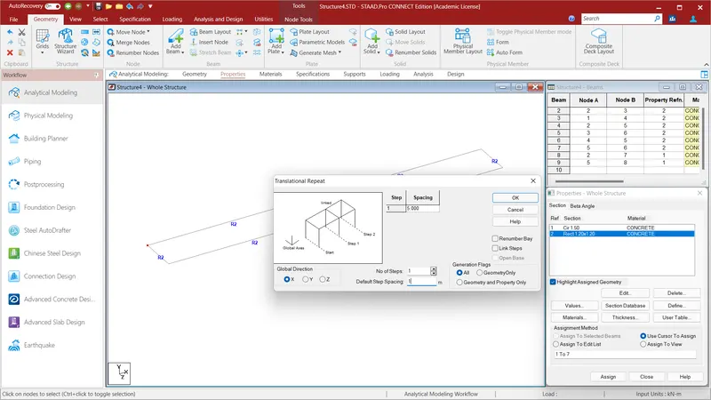
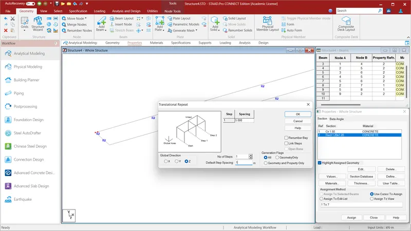
We will create Deck slab to the bridge . To do that go to Geometry option and select Translational Repeat and in Global X Direction by assigning the No.of Steps=1;Default Step Spacing=1m and click OK using node cursor. Now again select the two node sand again go to Geometry option and select Translational Repeat and in Global Z Direction by assigning the No.of Steps=1;Default Step Spacing=1m and click OK. Go to Geometry option and click Add Plate and connect all the nodes and using plate cursor create a plate in select option.
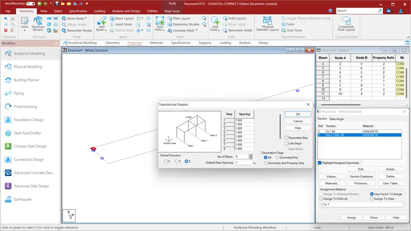
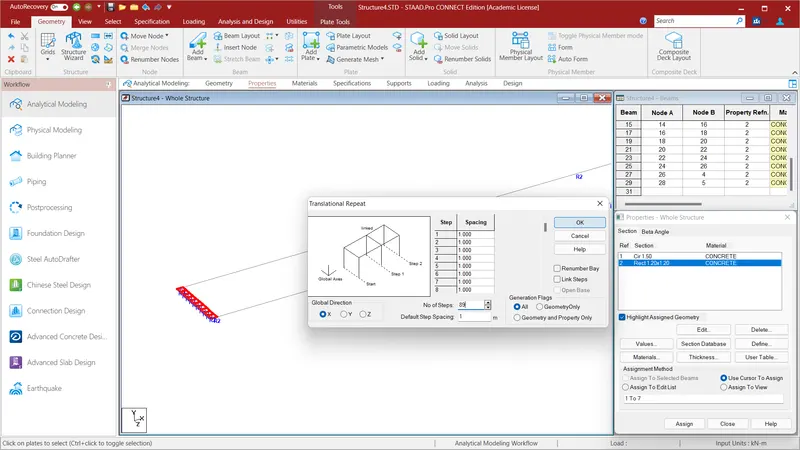
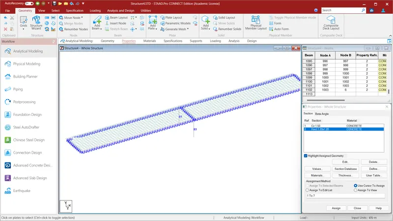
We shall apply the plates throughout the deck slab.To do that again go to Geometry option and select Translational Repeat and in Global Z Direction by assigning the No.of Steps=9;Default Step Spacing=1m and click OK using node cursor. Again go to Geometry option and select Translational Repeat and in Global X Direction by assigning the No.of Steps=89;Default Step Spacing=1m and click OK.We have created all the plates throughout the Deck Slab.
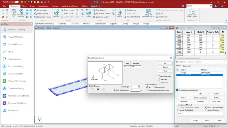
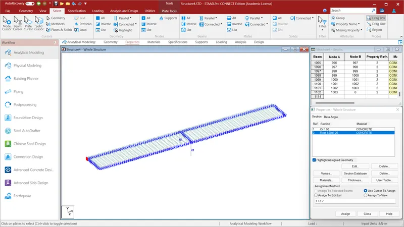
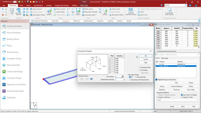
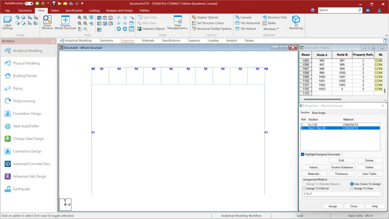
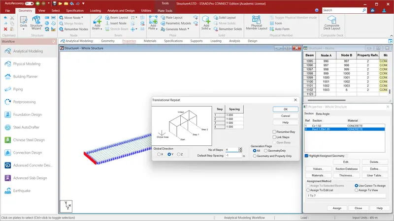
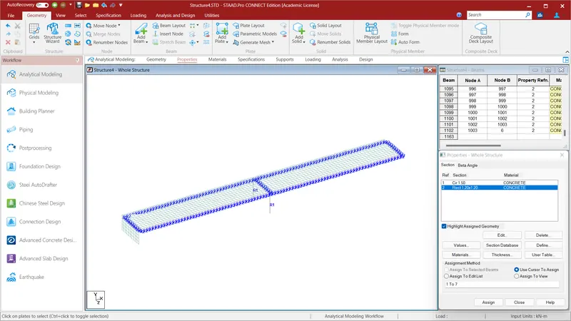
Go to Geometry option and select Translational Repeat and in Global Y Direction by assigning the No.of Steps=1;Default Step Spacing=-1m and click OK using node cursor. Again go to Geometry option and select Translational Repeat and in Global X Direction by assigning the No.of Steps=89;Default Step Spacing=1m and click OK. Go to Geometry option and click Add Plate and connect all the nodes and using plate cursor create a plate in select option.Again Go to Geometry option and select Translational Repeat and in Global Z Direction by assigning the No.of Steps=9;Default Step Spacing=1m and click OK using plate cursor. Again go to Geometry option and select Translational Repeat and in Global Y Direction by assigning the No.of Steps=4;Default Step Spacing=-1m and click OK. We will have created an Adutment Wall in the bridge.
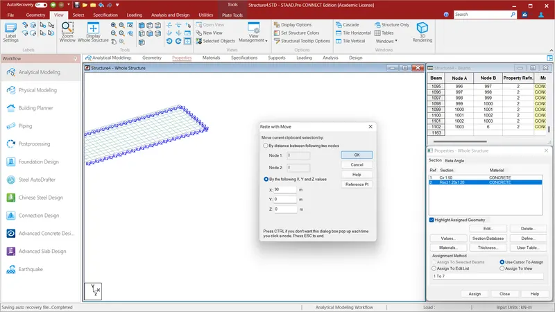
Now using plate cursor select all the plates and right click the mouse and copy all the plates and again right click the mouse and Paste Plate . A Plate with Move table will appear. Select the Referance Point and click OK. Now select the corner note at 90m length and click OK . The Abutment Wall on the other side will be created.
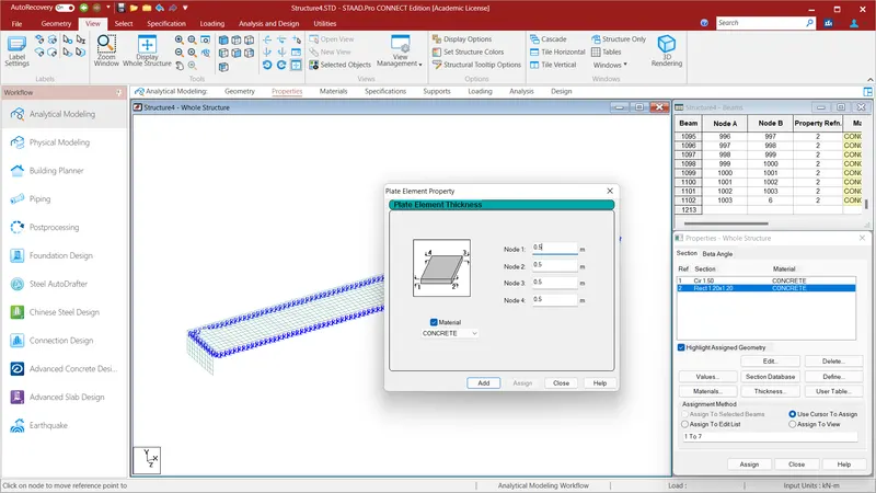
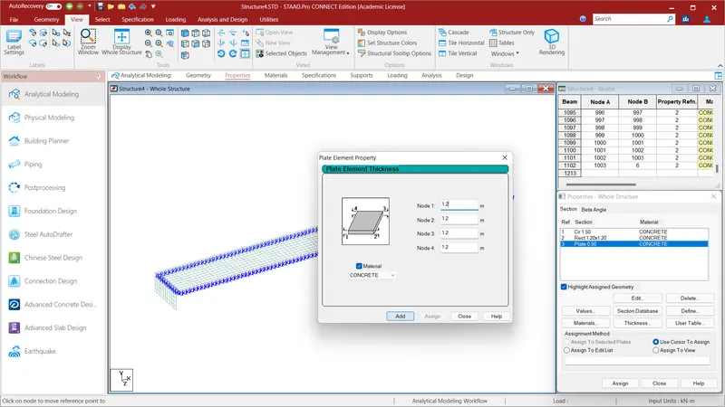
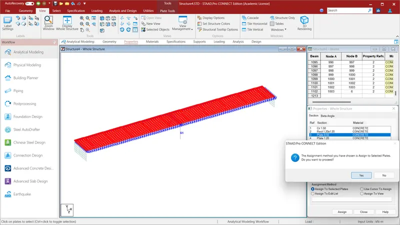
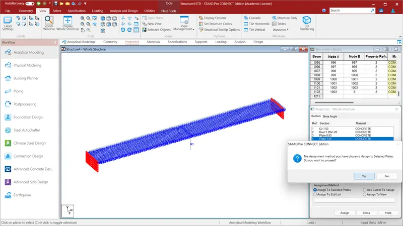
We shall assign properties to the Deck Slab and Abutment Wall. To do that go to Geometry option and select Specification Option and select plate Thickness give the values of Node 1=0.5m;Node 2=0.5m;Node 3=0.5m;Node 4=0.5m by using Concrete Material and click ADD.Now selct the Deck slab using plate cursor and Assign to Selected Beams and Assign and click ADD and YES. The properties to the Deckslab will be assigned. Again go to Geometry option and select Specification Option and select plate Thickness give the values of Node 1=1.2m;Node 2=1.2m;Node 3=1.2m;Node 4=1.2m by using Concrete Material and click ADD and Assign to Selected Beams and Assign and click ADD and YES. The properties to the Abutment Wall will be assigned.
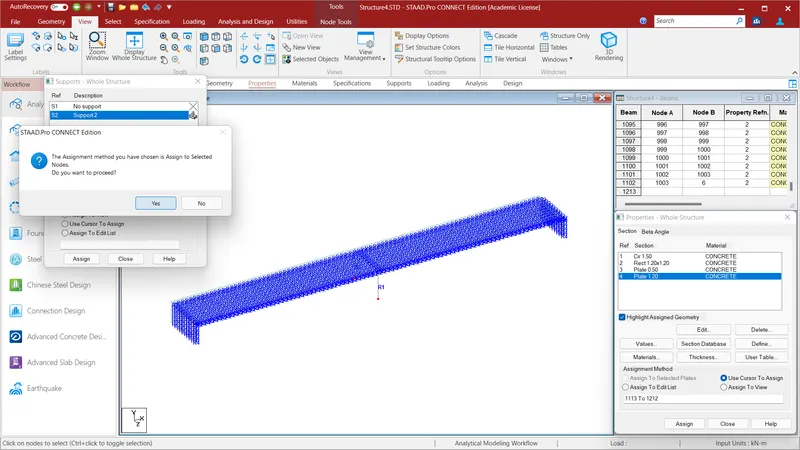
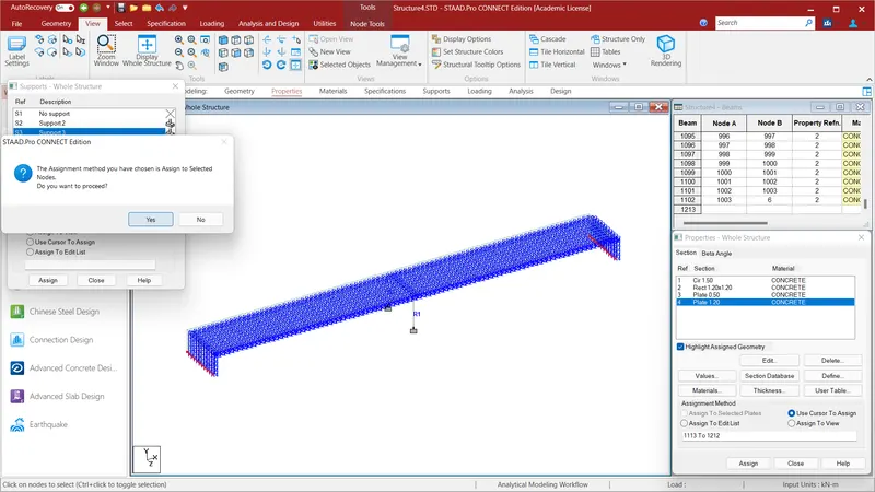
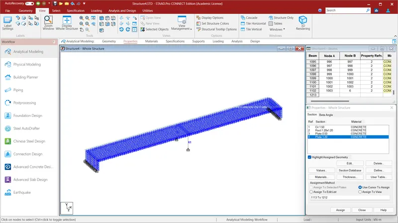
We have assigned all the properties to the structure . Now we will have Fixed support to the Piers and Abutment Wall and we will analyse the structure . Go to select option and select the node cursor and slect the bottom pier nodes and go to Geometry option and select Specification Option and select Fixed and click Add and select Support 2 and click Assign to Selected Beams and Assign and click ADD and YES. Again select all the Bottom Abutment Wall nodes on both sides of the structure and go to Geometry option and select Specification Option and select Fixed and click Add and select Support 3 and click Assign to Selected Beams and Assign and click ADD and YES.
RESULT:
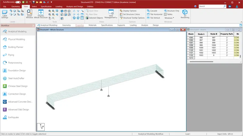
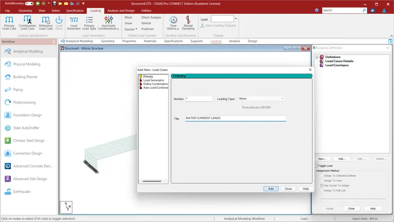
We shall assign current loads to the piers and abutment walls.Go to loading option and select the Load Case Details and give the title as WATER CURRENT LOADS and click ADD and close .
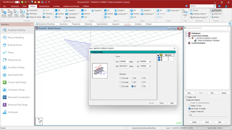
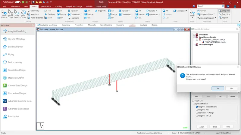
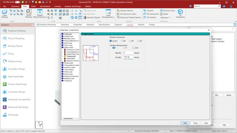
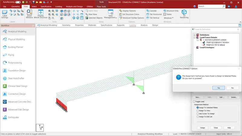
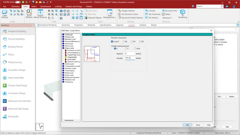
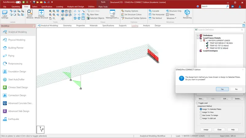
We shall apply loads to the piers . Select the WATER CURRENT FORECE and click ADD and go to Member Load and select Trapezoidal and give the following values as follows W1=0;W2=926.64KN/m^2 and d1=4m;d2=7.36m. Now select the piers and click Assign to Selected Beams and Assign and click ADD and YES.Again Select the WATER CURRENT FORECE and click ADD and go to Plate Load and select Trapezoidal and give the following values as follows Start (f1)=0;End(f2)=741.312KN/m^2 and Local Z Direction. Now select the Plates of Abutment Wall upto 2m fron the bottom and click Assign to Selected Beams and Assign and click ADD and YES.Again Select the WATER CURRENT FORECE and click ADD and go to Plate Load and select Trapezoidal and give the following values as follows Start (f1)=0;End(f2)=-741.312KN/m^2 and Local Z Direction. Now select the Plates of Abutment Wall upto 2m fron the bottom and click Assign to Selected Beams and Assign and click ADD and YES.We have assigned the WATER CURRENT LOADS to the walls and piers.
REPORT:
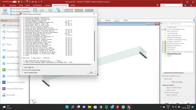
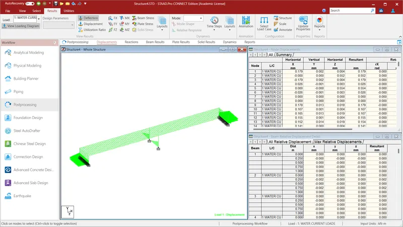
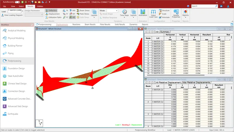
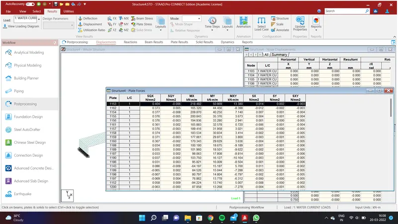
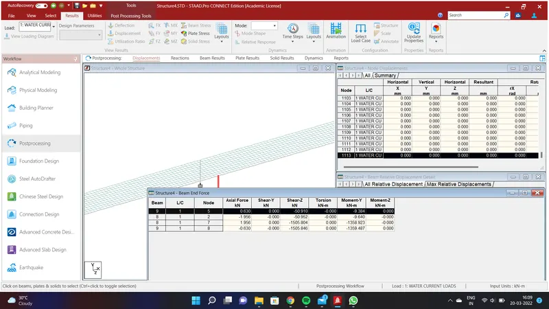
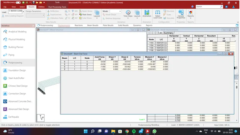
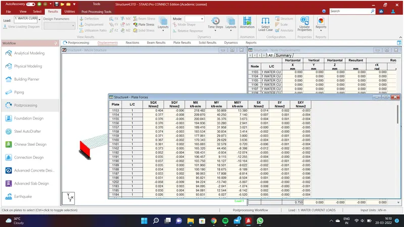
For the given problem the moment is calculated at X and Y and also deflection at Y.
Plate Stresses are calculated
Beam End Forces are calculated.