Week 7 Challenge
AIM and INTRODUCTION :
- To calculate the water current load for the given bridge and apply the calculated loads in the staad pro.
- The water current loads are formed due to temperature and density gradients.
- The topography and ocean basins also influence water currents.
- The major ocean currents are
> North Equatorial currents.
> Atlantic currents.
> North Pacific currents.
> South Indian currents.
- P= 52 * K * V * V
- P is the pressure intensity due to water current.
- v maximum velocity of water current.
- where K is constant, varies accordingly with shape.
- The maximum velocity v = 1. 414 * V mean.
- The High flood level is above 2m from the foundation level.
- The mean velocity is given as 3m/s
PROCEDURE :
- first, we need to calculate the water current load using the above formula 52*k*v2
- The k value differs with pier shape
- for square = k = 1.50
- for circle = 0.66
- for semi circular = 0.66
- triangular = 0.50
- Here we use circular
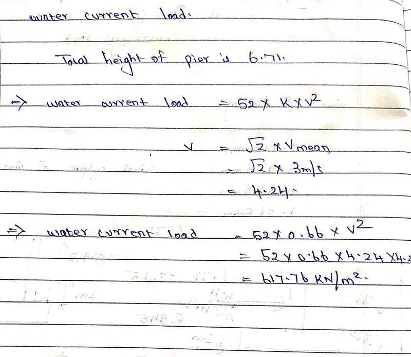
- So we need to apply the load of 617.76 kn/m2 load to the pier as a water current load.
step by step procedure :
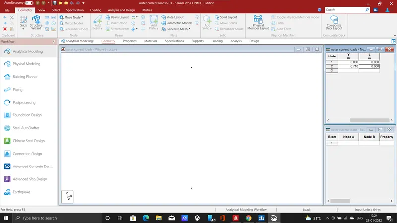
- The first step is needed to enter the nodes for the pier, he (0,0,0),(0,6.710,0).
- connect the nodes by using add beam command in the geometry section.
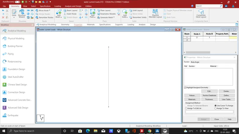
- The pier is added for a height of 6.710m with reference to the given question.
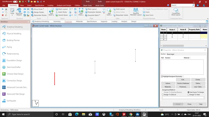
- Now use translational repeat command for creating the bridge span, add two piers at distance of 22.5m each.
- In the translational repeat command add spacing as 22.5 and no of steps as 2 in X direction.
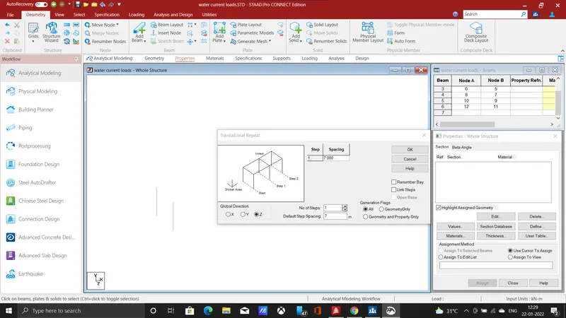
- Select all the piers in the x-direction, now use translational repeat command in the z-direction at a spacing of 7m and number of steps as 1
- Thus the piers have been added in z-direction thus creating the width of the bridge.
- connect the piers by longitudinal and cross beams using add beam command.
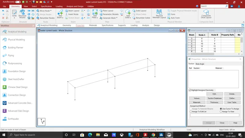
- The bridge is formed by adding the longitudinal and cross beams girders as shown above.
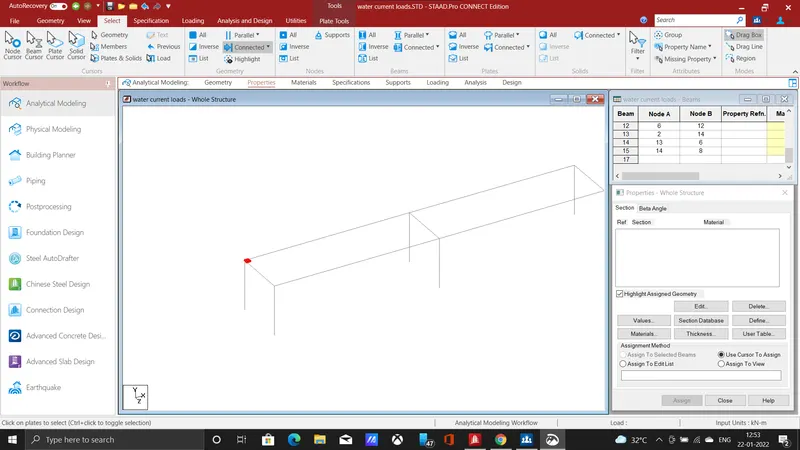
- Add a plate to form a deck slab for the bridge, using translational repeat command add nodes in the x and z-direction.
- add a new node at a spacing of 0.5m in the x-direction by selecting existing using repeat command.
- select the two nodes and copy them in the z-direction at a spacing of 0.5 with no of steps as 1.
- Use add plate command, connect the four nodes and create a new plate.
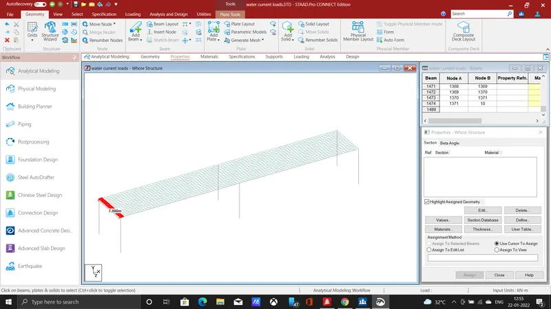
- form a deck slab by repeating the plate for the entire length and width of the slab, using the translational repeat command.
- In the x-direction repeat for 89 steps at a spacing of 0.5m and in z-direction repeat it for 13 number steps at a spacing of 0.5m hence the entire bridge deck is formed.
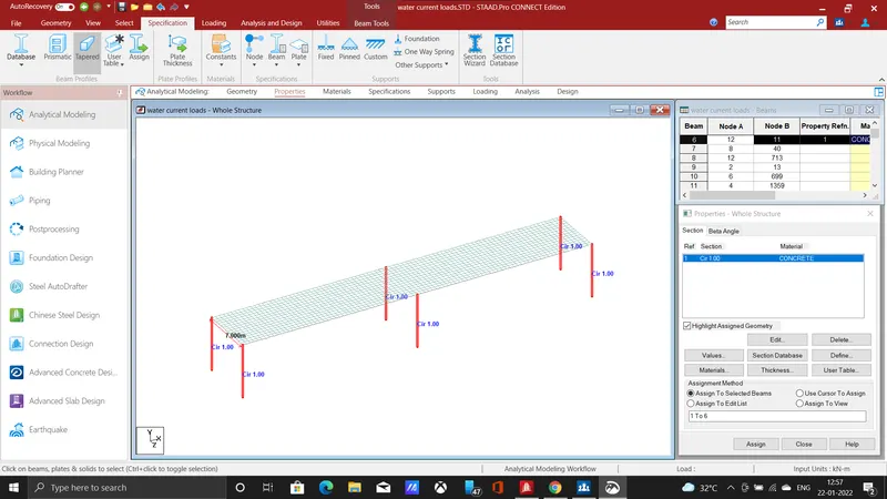
- After creating the deck we need to specify the section for the pier, add a circular section of dia 1m and assign it to the 6 piers
- select the piers and click on the section use assign to selected beam command thus the section is assigned.
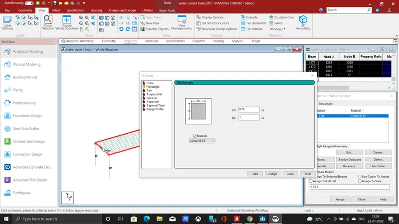
- Add a rectangular section of 0.75 * 1 m with material as concrete, select the cross beam and rectangular beam, assign the section to the beam.
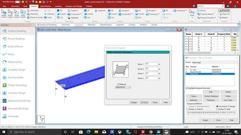
- Add a plate thickness of 300mm and select the deck plate to assign the geometry to the selected deck plates, Thus the sections are assigned with geometrical properties, the next step is to give loading to the structure.
-
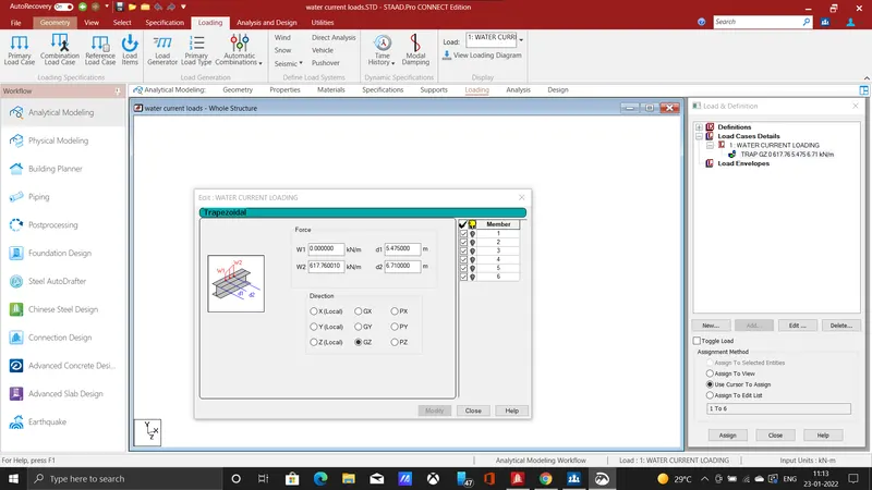
- In the load case details click add, enter the title as water current loads, select add click the member loads, in that member loads click on trapezoidal load.
- Enter the calculated force values, and enter the height up to which the load has been applied, the load will be acting for a height of 1.235 m.
- The high flood level will be at a height of 2m from the foundation level, some parts of the foundation will be beneath the soil surface, we need to subtract them and then we can apply the load.
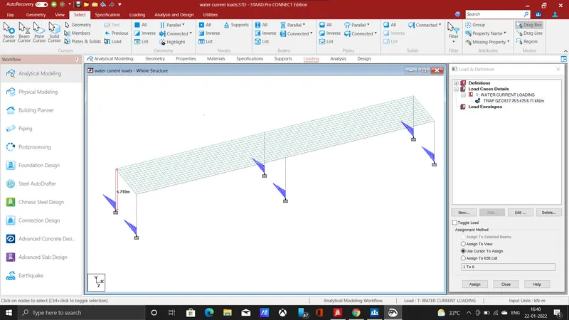
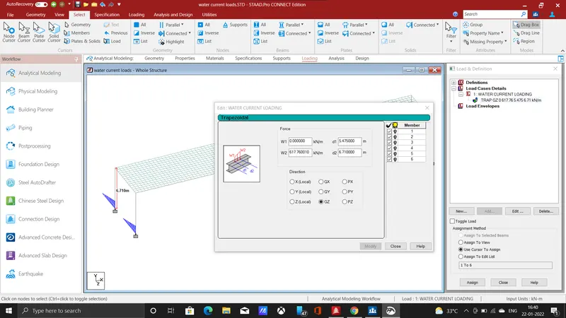
- The load is applied in the z-direction, at the calculated height, next step is to analyse the structure, use the run analysis command to analyze the structure.
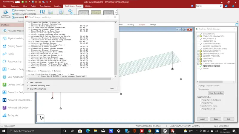
- Enter into post-processing mode, to analyse the structural behaviour of the bridge.
RESULT :
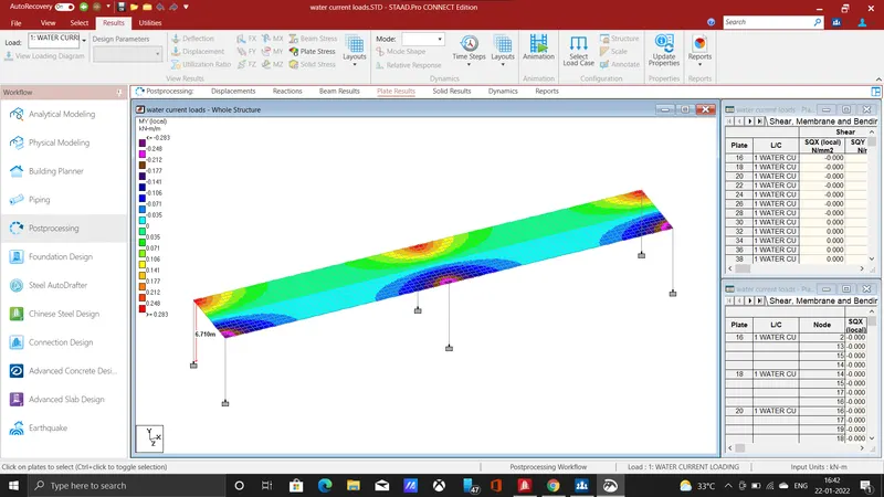
- Click on the plate stress in the results tab, the plate stress will be shown in contour image, The plate stress shown for mY local has a maximum value of 0.283 kn-m/mand minimum of - 0.293
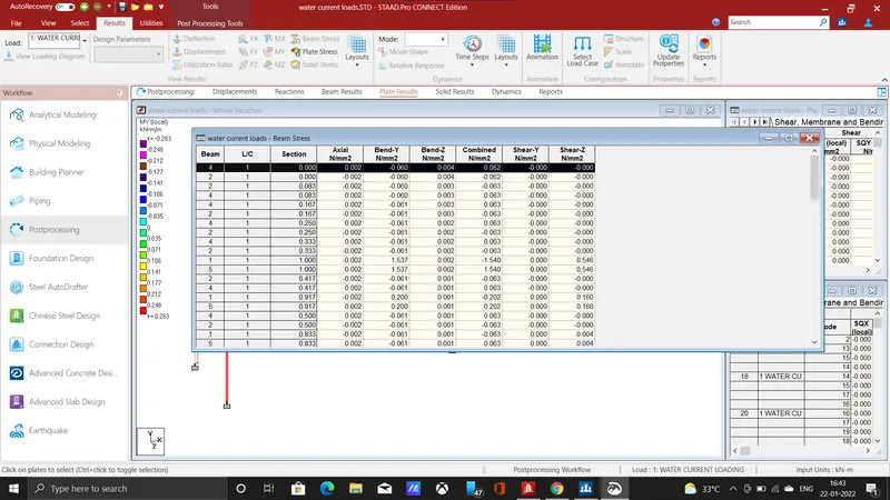
- The beam stress value has been shown for the applied water current loads, click on the report and select the beam stress.
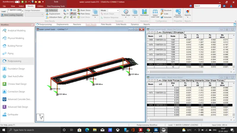
- The beam results have been shown for pier click on annotate, select beam click on beam ends, select mY .
- Hence the water current load has been calculated and applied for the designed bridge using staad pro.