Week 1 Challenge
Aim :
To perform a structural analysis of a BoxGirder bridge using staad pro and to calculate the dead loads acting on the structure.
Introduction :
In this assessment we are going to calculate the various dead loads of structural elements and apply these loads on the structure to perform analysis using Staad pro.
The Dead-load of Box girder is calculated by knowing
Dead loads acting on superstructure :
(1) self-weight of Deck slab.
(2) self-weight of Parapet.
(3) self-weight of Box Girder.
(4) self-weight of the structural elements
Dead loads acting on substructure:
(1) self-weight of the pier
(2) self-weight of pier cap
(3) self-weight of the foundation
Procedure :
To the calculate self-weight of each structural element we have the formula : Area *unit weight
unit weight of Rcc is 25kN/m3
Let us calculate the Dead on super structure :
Self-weight of Deck slab :
=> width * Thickness * unitweight
=> 10.2m*0.225m*25kN/m3
=> 57.375 kN/m
Self-weight of Girder :
Box girder shape splitted into rectangle and triangle for area calculation
self weight = length or height * thickness * unitweight
(1)=> 2.175*0.250*25
=> 13.5kN/m
(2)=> 4.020*200*25
=> 20.1kN/m
(3)=> 0.5*1.2*25
=> 15kN/m
(4)=>2.175*.189*25
=>10.25kN/m
Dead load on sub structure :
self-weight of the pier :
=> pi/4*2.5*2.5
=> 4.9kN/m
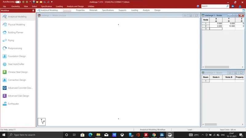
Here the nodes value had been given as (0,0,0) and (0,12,0) for the formation of Pier.
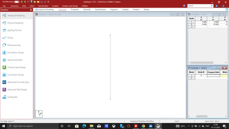
After the pier formation, we need to create the beam by connecting the above two nodes
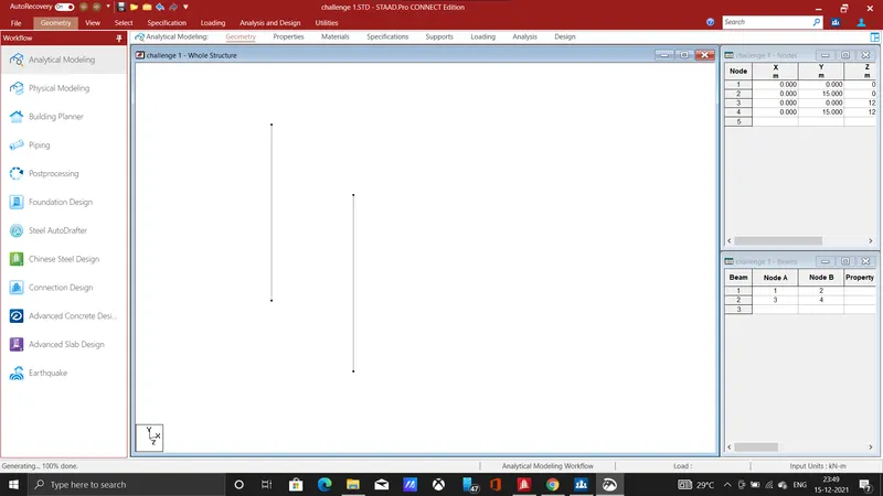
Hence the span between pier is given as 12m, hence the value is given to form another beam by using transitional repeat tool.
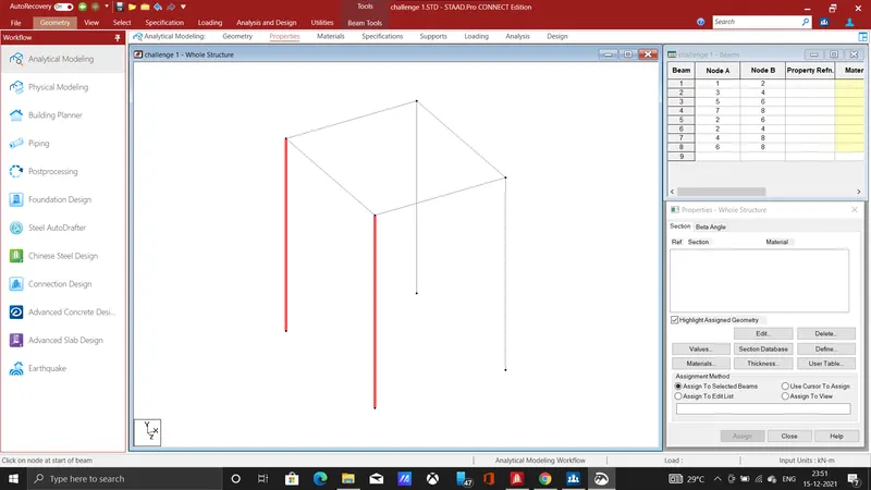
The girder and side beam had created by joining the nodes of pier and width of the deck slab is 10.2m.
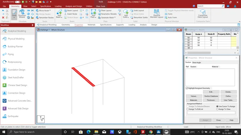
The deck has formed by using the plates as a floor for the deck slab, each plate has given the dimension as 0.6,0.5 and the transitional repeat tool has been used for the formation plate in the whole slab.
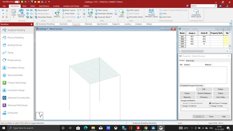
The above image shows the deck slab formed using plate as for the width of 10.2 m.
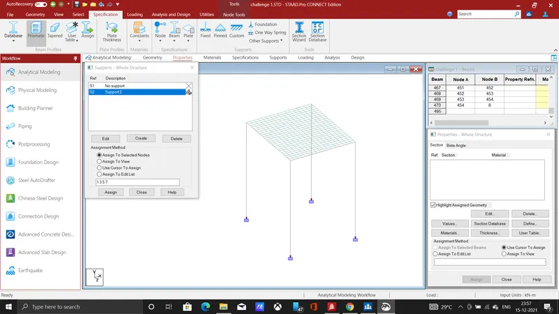
The fixed support is given to the each pier so that both ends are supported and fixed in a place.
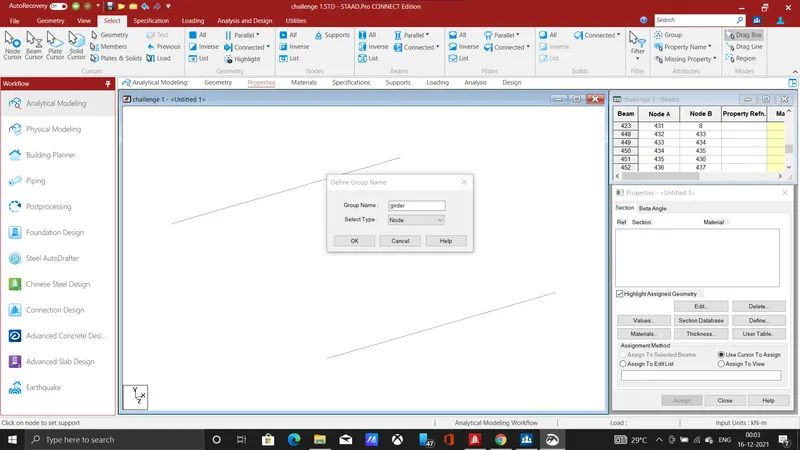
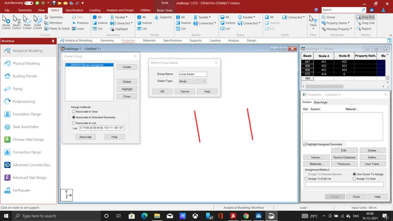
The girder that is longitudinal beam and crossbeam is grouped individually by using the grouping tool, so that we can assign properties and dimension easily for the each structural member.
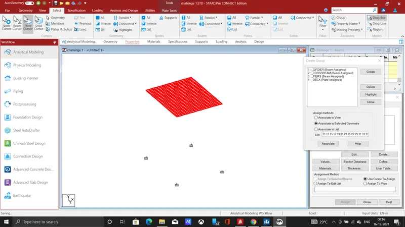
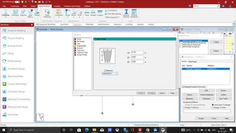
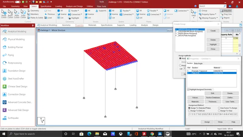
Each structure is specified by shape and dimension, Here it is a box girder so its dimension is given accordingly with reference from the question, the plate thickness is provided as 0.4m.
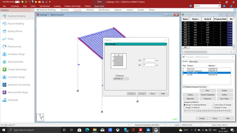
The crossbeam is specified as a rectangle of size 1.5m. hence The property is assigned to all structural member.
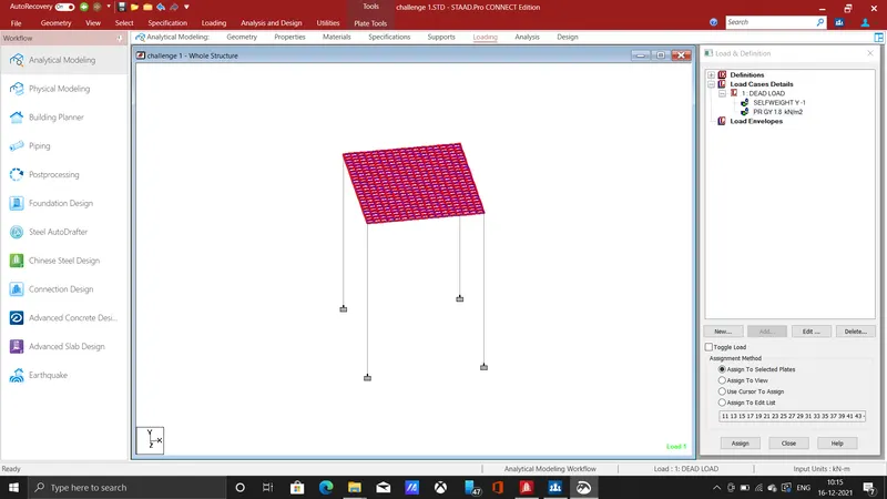
The next step is to give loading to the member, hence the dead is assigned by giving the self weight command, and also pavement finishers load is taken as 1.8kN/m which is acting over the deck slab.
Result :
The result will show the various shear force, bending moment, deflection values for box girder bridge.
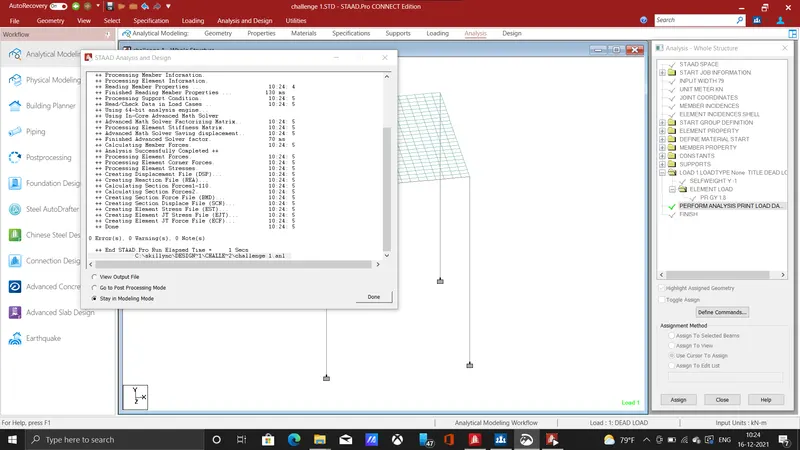
The box girder bridge is specified with all structural details and analysis is carried out by using run analysis command and then post processing mode is used for taking appropriate results.
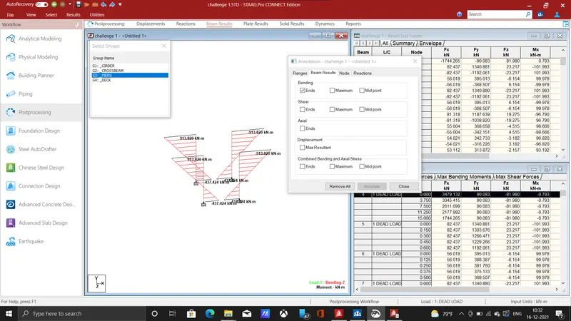
The above one shows for the pier at the ends has a maximum bending moment value of 913.80KNm and minimum value of 437.4KNm .
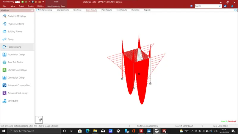
It shows shear, Bending moment, Deflection, for the girder, piers and as well as for the deck slab.
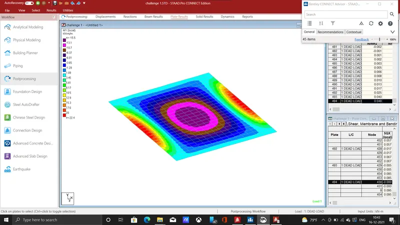
The above one is a contour image for the moment in plates, it is analyzed by using the plate result command.
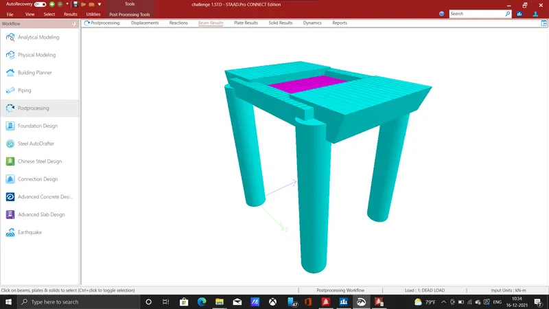
This one 3d rendered image for designed box girder bridge for the given question, Hence the various dead loads has been calculated and analyzed by using staad pro.