Week 2 Challenge
Aim and Introduction :
To design an I girder bridge and to apply the IRC live loads using staad pro thus performing the structural analysis for the bridge.
The live load consists of standard wheeled vehicles or track vehicles or special vehicles, the types of loading are as follows.
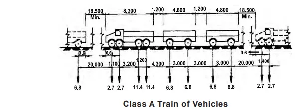
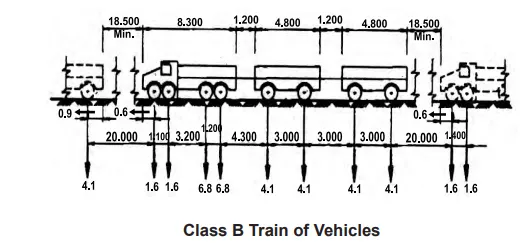
1. IRC class A and class B loading,
class A vehicular loading are shown below,
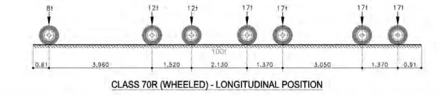
2. IRC class 70R loading, (wheel and track loading)
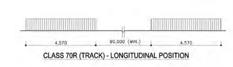
3. Footway loading
For all parts of bridge floors accessible to pedestrians, animals and for all footways the loading shall be 400 kg/m2. For the design of foot over bridges, the loading
shall be taken as 500 kg/m2.
4. special vehicle
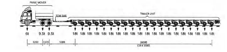
The above image shows the longitudinal axle arrangement of special vehicle loading.
Procedure :
In this analysis, we need to design a bridge and to specify the given dimensions for each structural member of the bridge, and apply the live loads to analyse the structure.
The design steps are given below :
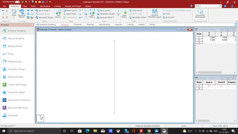
>>. First, we need to enter the node for the pier,(0,0,0) (0,12,0) and then connect nodes by using add beam icon.
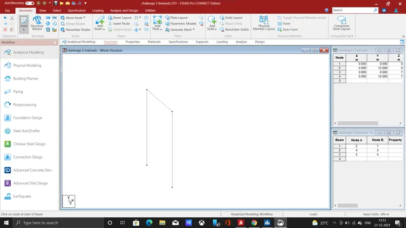
>>. Add another pier by using transitional repeat icon at a distance of 7m which is the width of the deck slab, where carriageway will be formed, then connect the two piers by adding a cross beam.
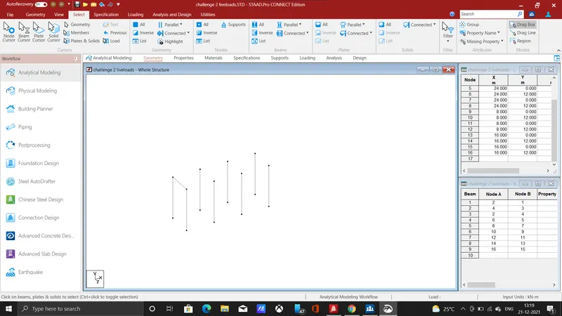
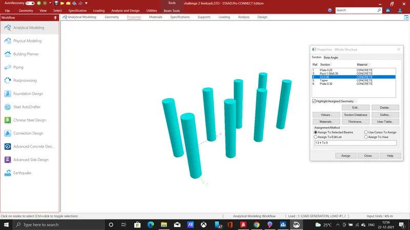
>>.The span of the bridge is given as 24m, By using transitional repeat command at the spacing of 8m, of 3 steps another set of piers had formed, add cross beam by connecting the piers, the piers are given with dimension of 2m dia which forms the circular pier.
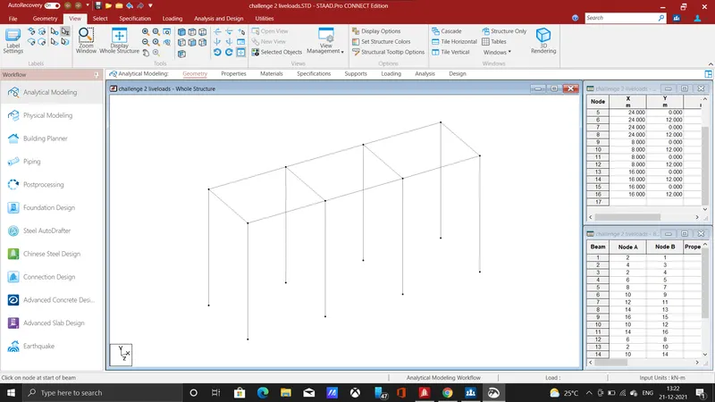
>>.The girder is formed for the entire span of the bridge by connecting the piers at a spacing of 8m each, thus forming the 24m span.
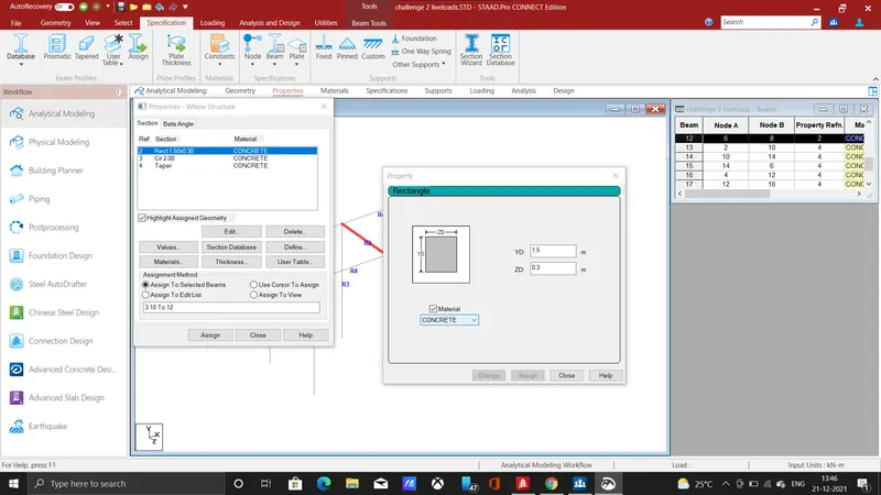
>>.we need to specify the dimension for the cross beam, as per the question it is considered as rectangular section, it is provided with breadth and depth as 1.5 and 0.3 m respectively.
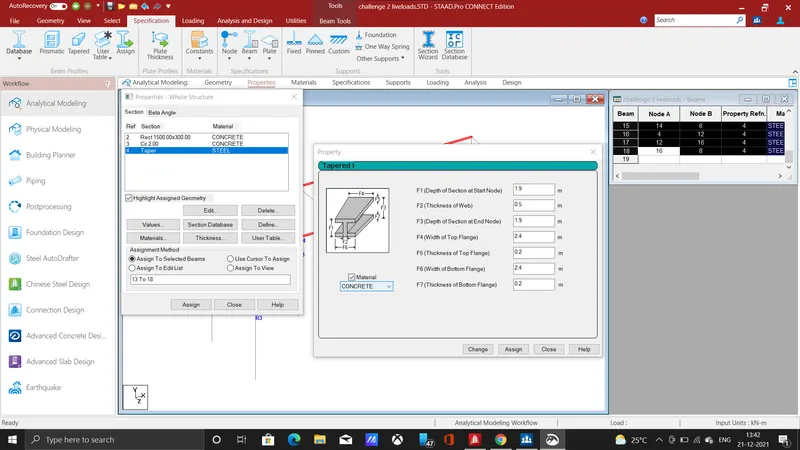
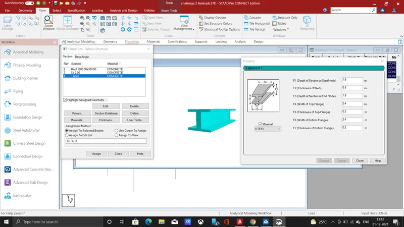
>>.The Girder is specified with above dimensions as I section with reference with the given question, The girder in the bridge is used to provide support to the deck by transferring load to the piers.
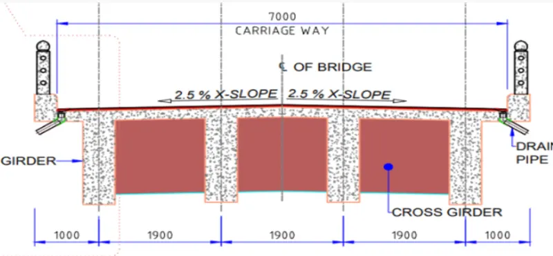
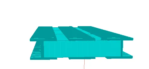
>>.This one shows the compared view of carriageway from the given question and designed 3d view, This shows the I girder and cross beam (cross girder).
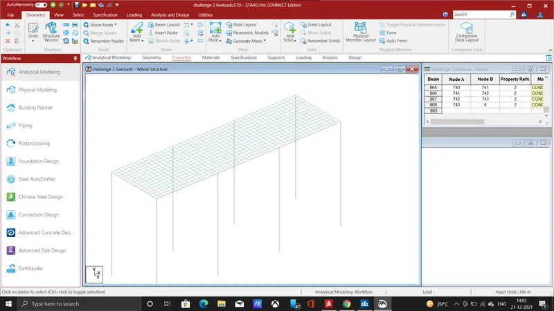
>>.The deck slab is formed by connecting the plates of 200mm thickness at the width of 7m for the span of 24, above the deck slab wearing course is constructed.
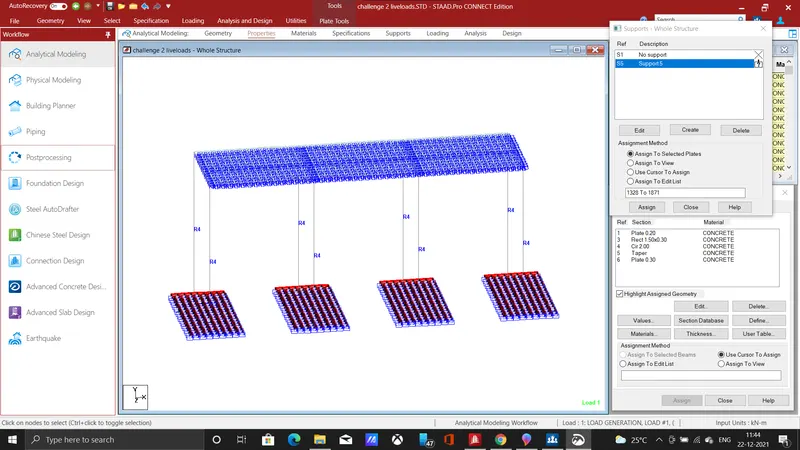
>>. By providing plates of thickness 300mm, and the bottom of the pier the foundation can be specified, plate is added by connecting the nodes which is created at the bottom by using add plate icon.
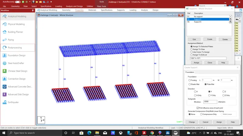
>>. Mat foundation is assigned to the pier by clicking the foundation icon and needs to enter the modulus values and to click on direction then aasign to plates.
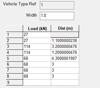
>> After assigning all the properties to the structure, load is need to be generated, in this model I provided IRC class A loading for vehicle width of 1.8m
>>.After assigning the load the bridge is needed to be analysed, hence the run analysis command is used for the analysis, that results can be taken in post-processing mode.
Results :
The above loading values are assigned to the structure and the load has been generated for modelled I girder bridge.
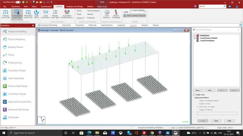
the above load values are assigned as per IRC class A vehicular loading.
The results for shear, moment, deflection, displacement had obtained in post-processing analysis.
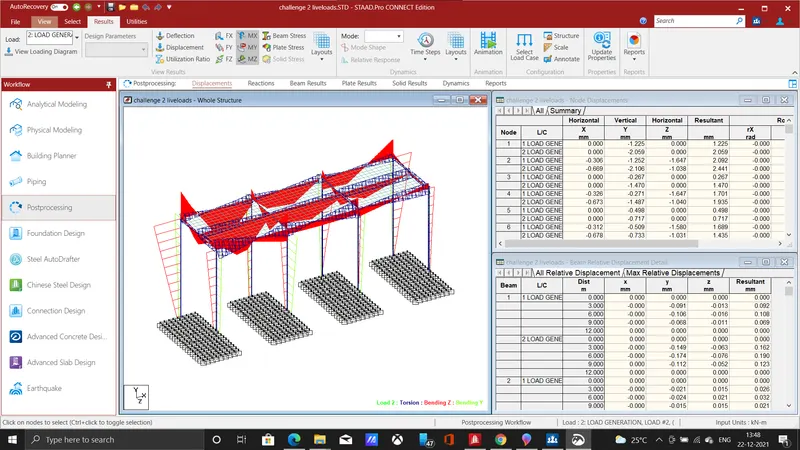
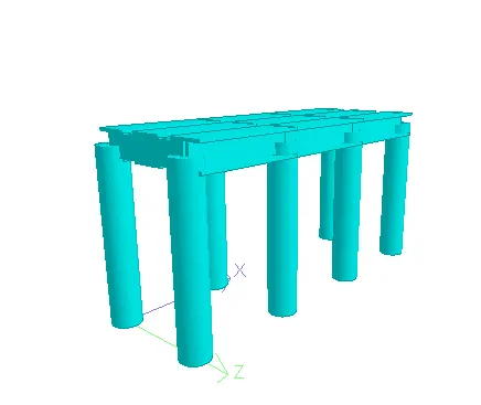
The three dimensional rendered view for the above designed I girder is shown