Week 5 Challenge
Aim and Introduction :
To Design a bridge of height 9m above ground level and to apply the wind load on the bridge using staad pro,
To find wind load:vz = vb*k1*k2*k3*k4.
where vb is the basic wind speed ,
Based on the wind speed, the locations were classified into five different zones
1.under 33m/s
2.33-39m/s
3.39-44m/s
4.44-47m/s.
5.over 50m/s
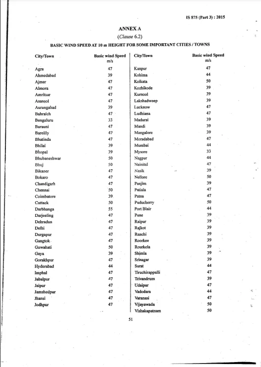
with reference to IS 875 part 3, the wind speed for a given location in Mumbai will be 44m/s, given that location is located in open terrain with a well-scattered obstruction height of less than 10m.
Procedure :
To Calculate wind load (vz) = vb*k1*k2*k3*k4.
=>> vb=44m/s
=>> K1 from table 1 IS 875 part 3 2015
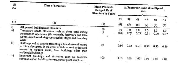
=>> k1 = 1.07
==> k2 from table 2 IS 875 part 3 2015
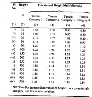
=>> k2 = 1.05
=>> k3 from IS 875 2015 class 6.3.3 IS 875 2015
=>> k3 = 1
=>> k4 from IS 875 2015 location within 60km radius of ocean
=>> k4 = 1.3
vz = 44*1.07*1.05*1.0*1.30
vz = 64.26m/s.
wind pressure = 0.6 * vz * vz
= 2.4 kN/m2
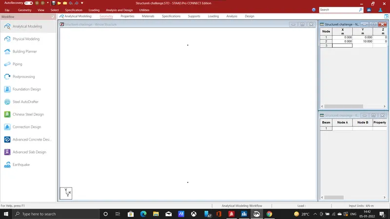
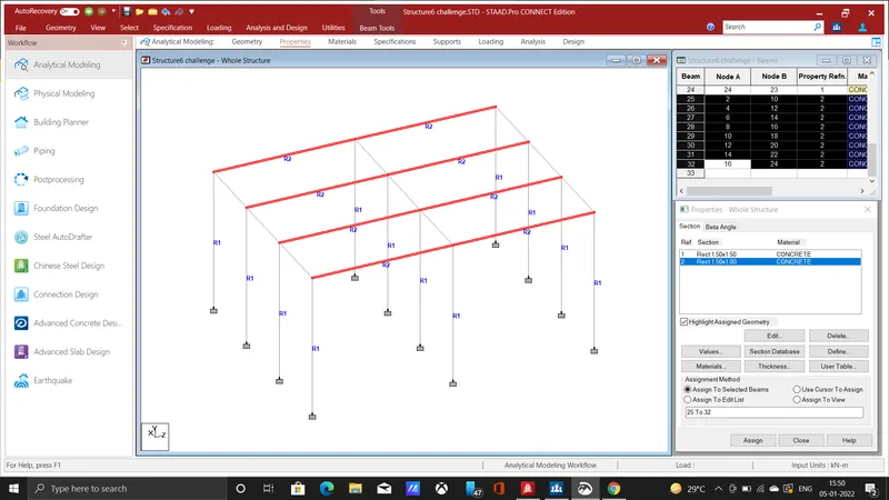
- First enter the node values as (0,0,0) (0,10,0) given that height of the pier above ground level is 9m, so additionally add 1 metre in height which is below the ground level for footing join the two nodes by using add beam command.
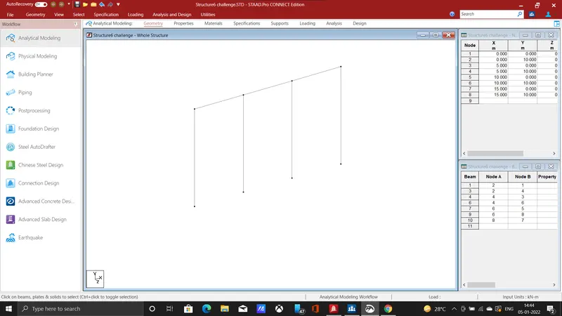 .
.
- use translational repeat command, enter spacing as 5m no of steps as 3 in the x-direction to provide another 3 no of piers, connect the nodes by beam using add beam command.
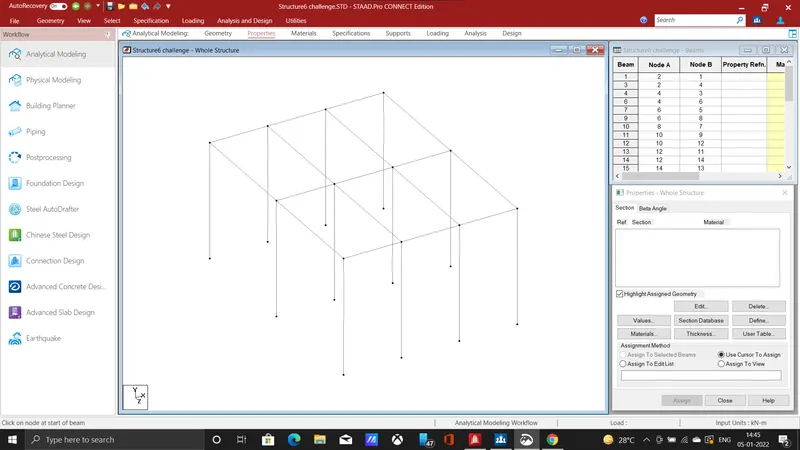
- use translational repeat command in z direction ,enter spacing as 10m and no of steps as 2, connect it using add beam thus bridge of 15m in x-direction and 20m in z-direction is formed.
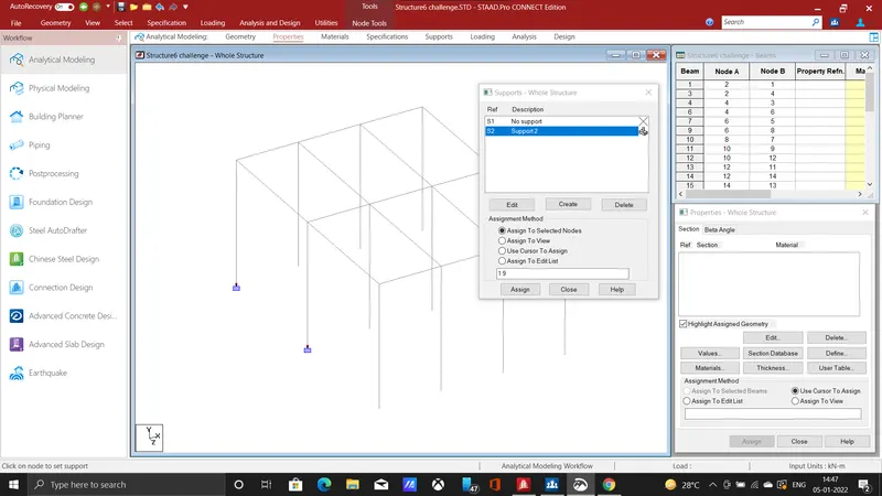
- add fixed support in the specification tab, select the bottom nodes of each pier by using node cursor and click on assign to selected nodes thus fixed support has been created to the piers.
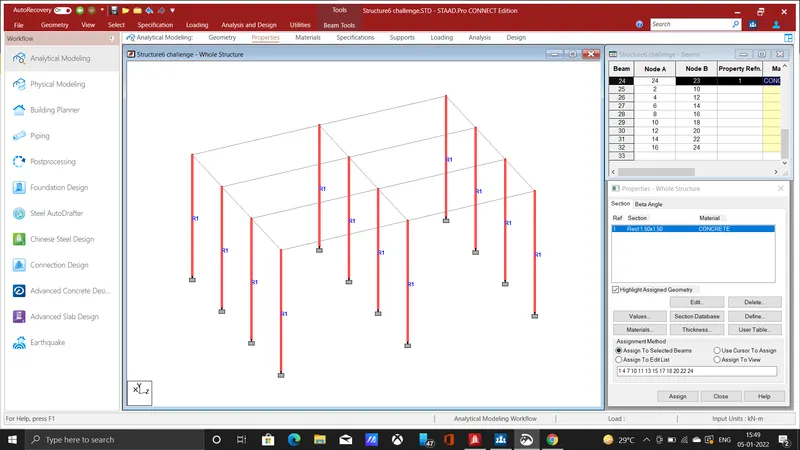
- next, we need to assign property to the members, click on the specification tab then use prismatic,add rectangular section of 1.5m * 1.5m select the piers and assign the property.
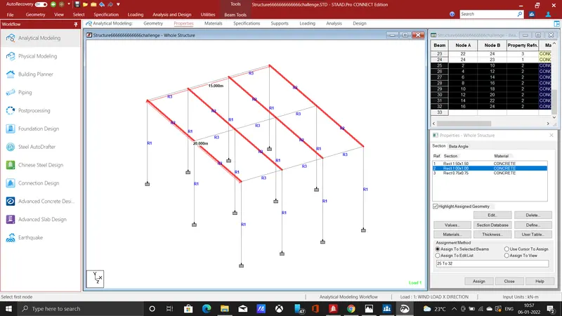
- Also assign property to girders, similarly on specification tab click use prismatic and add rectangular section of 1.m * 1m select the girders and assign the property.
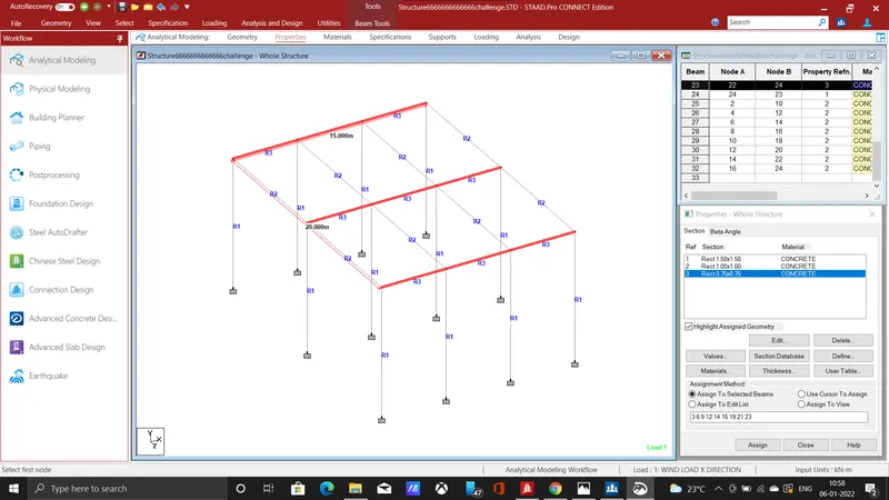
- Assign property to girders ,add a rectangular section and then assign it to the beams, hence the piers and girders were assigned , support were provided, next we need to apply loading.
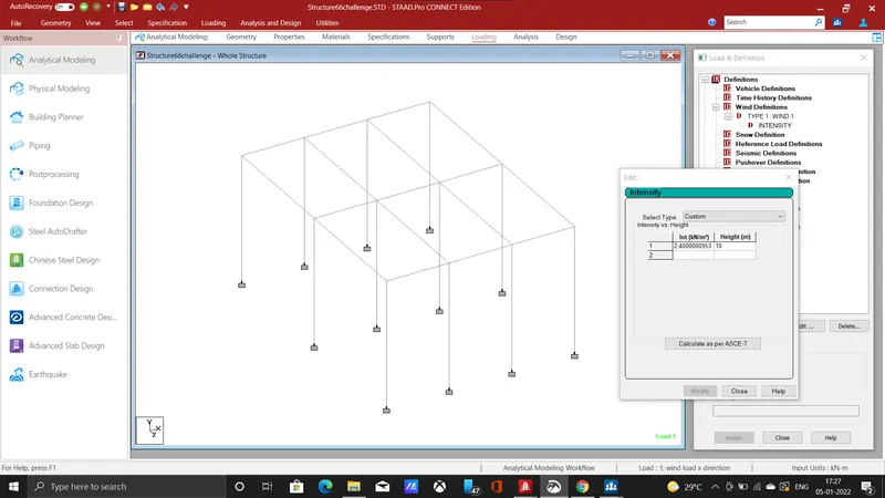
- In the loading tab click on wind load definition, select type custom enter wind intensity value as 2.4 kn/m2 at a height of 10m .
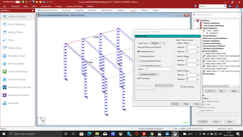
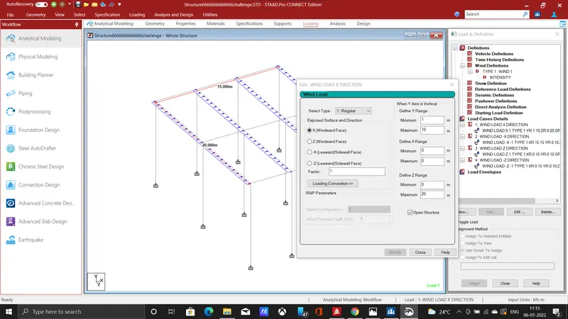
- The above two image shows the wind load along x direction , the difference between them is y co ordinate, which shows that height of pier above ground is 9m , and 1 metre below is foundation.
- 1st picture the load is applied for whole 10m height and in 2nd picture the load applied for 9m that is 1m from foundation to top 10m ,
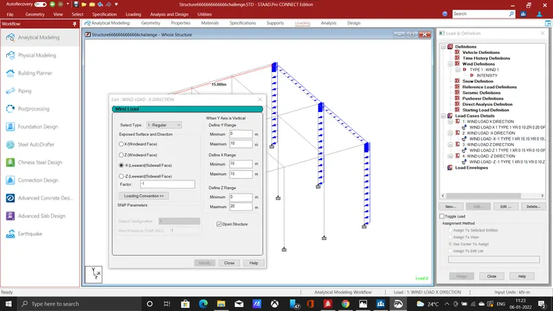
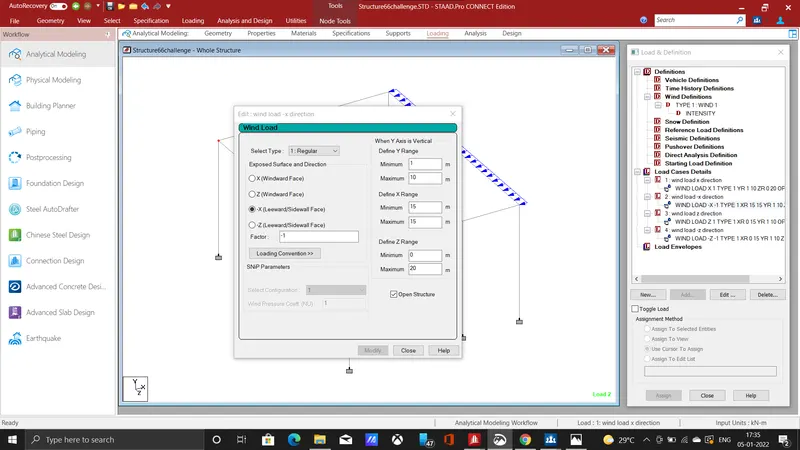
- The wind load is applied in - x direction ,click -x leeward side in wind load tab enter factor as -1 which represents the wind is acting in negative x direction.
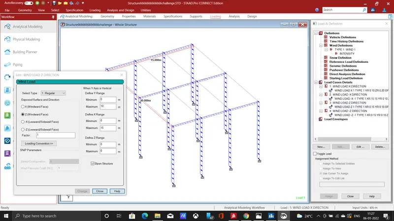
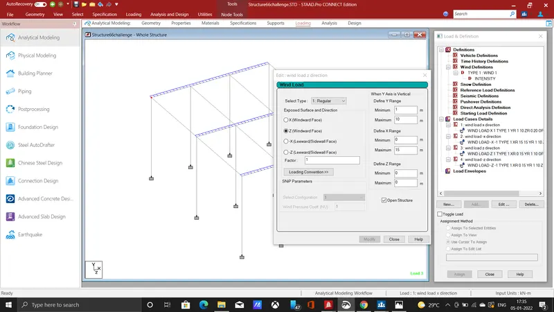
- same like in x direction the wind load is applied in z direction for whole height 10m and also for 9m height which is only for the structure above ground level.
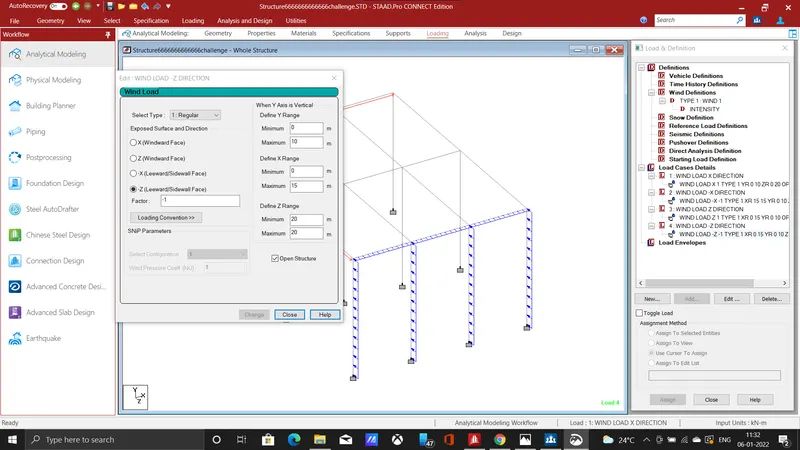
- The above shows that wind load is applied in negative z direction in which factor value is entered as -1 which represents the negative z direction ,and also enter the range value for each direction.
- The load has been applied to the members, therefore click on analysis and design button and then click run analysis command for further structural analysis.
RESULT :
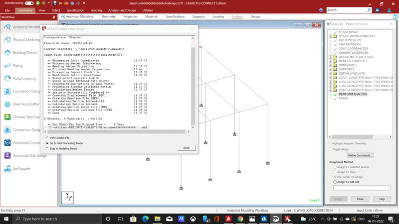
- click on the post processing mode button, then post processing tab will open so we can analysis the behaviour of the bridge for the applied loading.
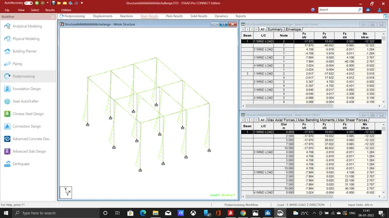
- above image shows the M(y) beam result for the wind load along z direction.
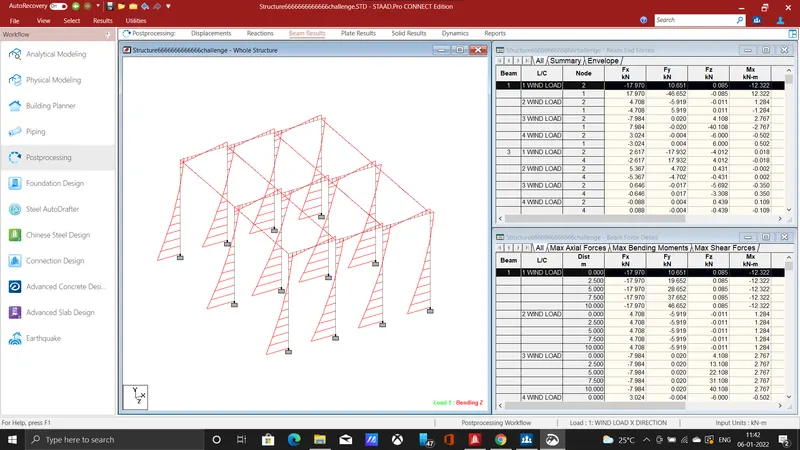
- the above image is the load along positive x direction and bending on z direction M(z),
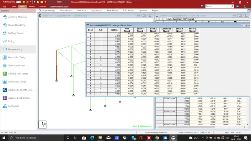
- The beam stress for selected beam is tabulated above, click on reports in results tab ,select beam stress and then click bending direction then select sorting click ok.
- Hence the bridge has been designed and wind load was applied.