Week 7 Challenge
AIM : Water current loads on bridges using given data
INTRODUCTION :
- In this challenge i have to calculate water current loads
- Some values are assumed to make a model and to do calculations
- Waters velocity is very important factor which will affect on the water current loads
CALCULATIONS :
GIVEN DATA :
- The high flood level is 2 m above the foundation level.
- The span of the bridge is 45m.
- The mean velocity of the river is 3 m/s.
ASSUMED DATA :
- Width of bridge = 3m
- Height of the pier = 5m
- 1.5mx1m rectangular pier size
Height of pier subjected to water current forces : 2m
- MAXIMUM VELOCITY = `SQUREROOT`2 x Mean velocity = SQUREROOT 2 x 3 = 4.2`
- `WATER CURRENT LOADS : 52 X K X V X V = 52 X 1.50 X 4.2 X 4.2 = 1402.25 kg/m`
so this value is in kg/m2 then we have to convert it into kn/m2 = 1402.25 kg/m2 = 13.75kn/m2
In the staadpro we apply the water current loads in Uniformly distributed load so convert this value in kn/m
13.72 x 2 = 27.5kn/m (2 = height of pier subjected to water current load)
on the 1m side of the bridge 27.5kn/m load we have to apply
on the 1.5m side= 1.5 x 27.5 = 41.25 kn/m
PROCEDURE TO CREATE A MODEL :
STEP 1 : DRAWING READING :
In this step firstly i read the question i read the drawing carefully but some values are not visible clearly
thats why some values are assumed while making a model in the staad pro .
STEP 2 : GEOMETRY OF THE BRIDGE :
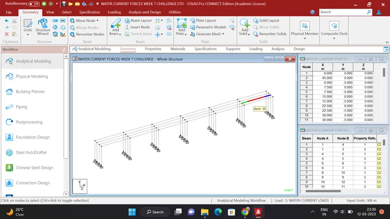
In the above photo to create a geometry following steps are followed :
- Created a node at 0,0,0 then using translational repeat another node is created in Y direction at a distance of 5m added a beam betwen this two nodes and this beam is our 1st pier .
- Selected this created beam and by using translational repeat in Z direction at a distance of 1 m 4 piers are created . after that this 4piers are selected and by using translational repeat in X direction in 7.5 m distance 6 steps are created such as the span of the bridge is 45m . accurately.
- At the top portion girder beams are created by addeding beam by joining the nodes, girders and cross beams are created .
- At the bottom nodes fixed supports are given by using specification box and assigned this fixed support to all the piers of th bridge .
STEP 3 : ASSIGNED PROPERTIES TO THE COMPONENTS OF THE BRIDGE :
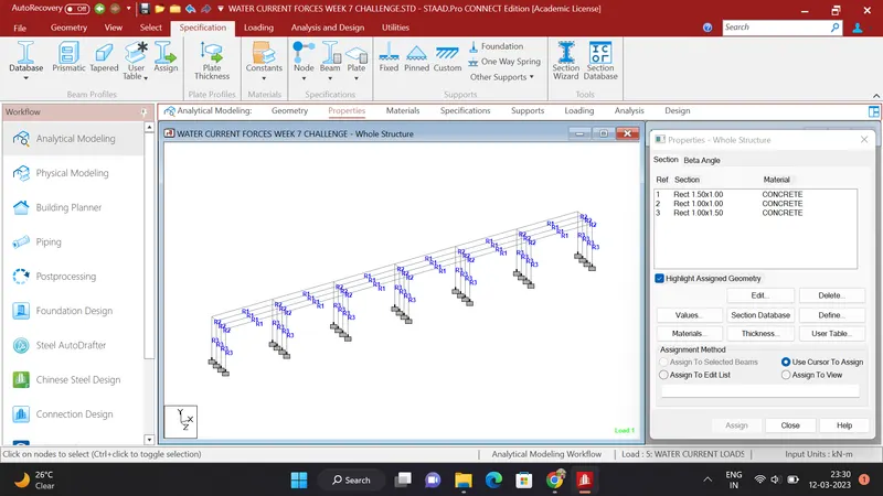
- In the above photo we can see that the properties has been given to the all the components of the bridge properties are as followes
- PIER = R3= RECT 1.00 x 1.50 CONCRETE
- GIRDER = R1 = RECT 1.50 X 1.00 CONCRETE
- CROSS BEAMS = RECT 1.00 X 1.00 CONCRETE
STEP 4 : LOAD APPLICATION IN THE STAADPRO :
LOAD CASES DETAILS :
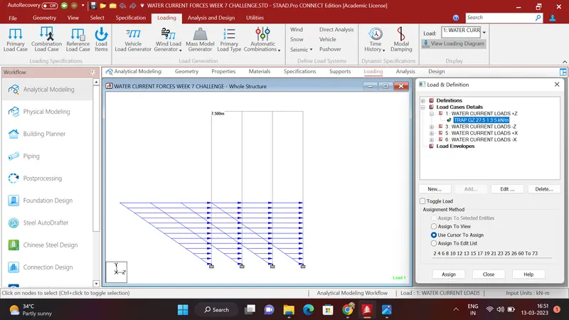
- The 27.5kn/m load is applied on the piers 2m above the foundation Generated a load case named as WATER CURRENT LOAD +Z added a member load which is trapezoidal load W1= 27.5 , W2 = 1 , d1= 3m . d2= 5m and created the load case and applied on th pier , Applied load as per below
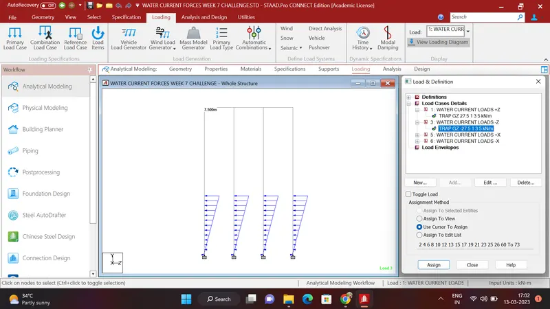
2. The second load case is named as WATER CURRENT LOAD -Z direction in this load case added member load in trapezoidal form W1=-27.5 , W2 = 1 , d1= 3m and d2= 5m and added this load and applied on the pier as per below picture
3. The third load case is generated named as WATER CURRENT LOAD +X direction this load is lies on the 1.5m width side so the load is 41.25kn/m as per calculation added the member load in trapezoidal form of W1=41.25kn/m , W2 = 1kn/m , d1 = 3m and d4= 5m
and this load is applied on the bridge as per below photo
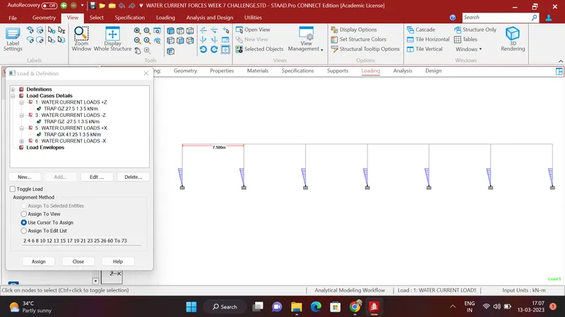
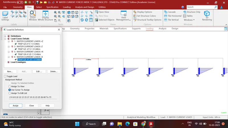
4. The fourth load case is generated named as WATER CURRENT LOADS -X direction addes member load in trapezoidal form as W1=-41.25kn/m . W2 =-1 kn/m , d1 = 3m and d2 = 5m and the load will be added
this created load is applied on the bridge as per below photo
STEP 5 : ANALYSIS
In the analysis and design box i runned the file and clicked on GO TO POSTPROCESSING MODE
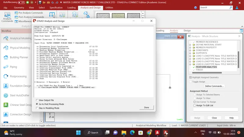
ANALYSED BEIDGE
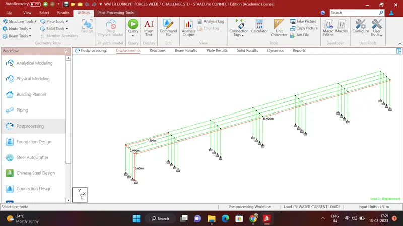
STEP 6: RESULT
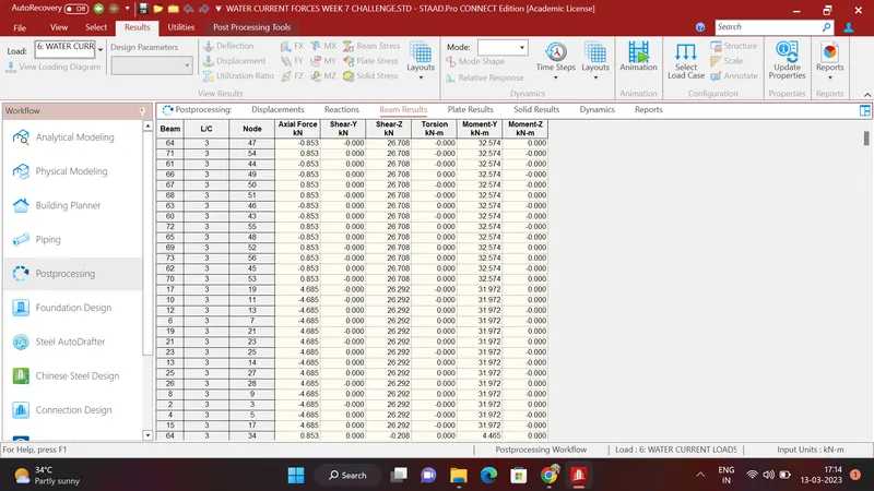
- BEAM RESULT Moment about Y axis from high to low
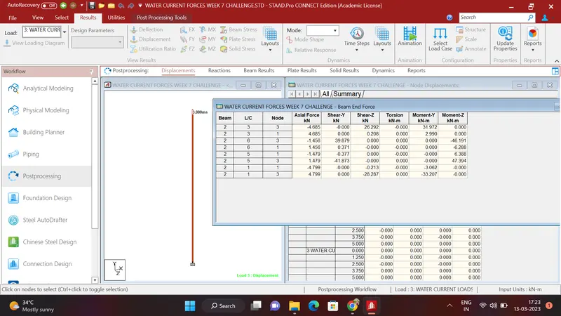
2. PIER RESULT SAMPLE
FINAL RESULT :
THE RESULT IS DIFFERENT FOR THE DIFFERENT LOADS DEFLECTION IS MINUTE
THE STAAD FILE IS ATTACHED BELOW .
THANK YOU