Week 7 Challenge
Modelling of Structure in STAAD Pro
1. Modelling of a structure exercise
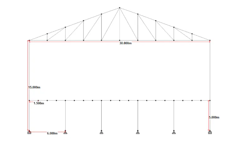
Model a structure with following details
- Bay spacing 5 m
- Span of Truss 30 m
- Shape of Truss – Pratt Truss
- Slope of truss 20 degree
- Height of the column 15 m
- Floor Beams at 5 m from base
- Secondary beams at 1.5 c/c
- Length of the building 50 m
- Column Supporting Floor Beam @ 6 m c/c Along the frame
Aim:-
To Model a structure with above details using STAAD Pro.
Introduction:-
- STAAD's full form is Structural Analysis and Design. STAAD Pro is one of the popular software that is used for analyzing & designing structures like – buildings, towers, bridges, industrial, transportation, and utility structures.
Procedure:-
Step 1:-
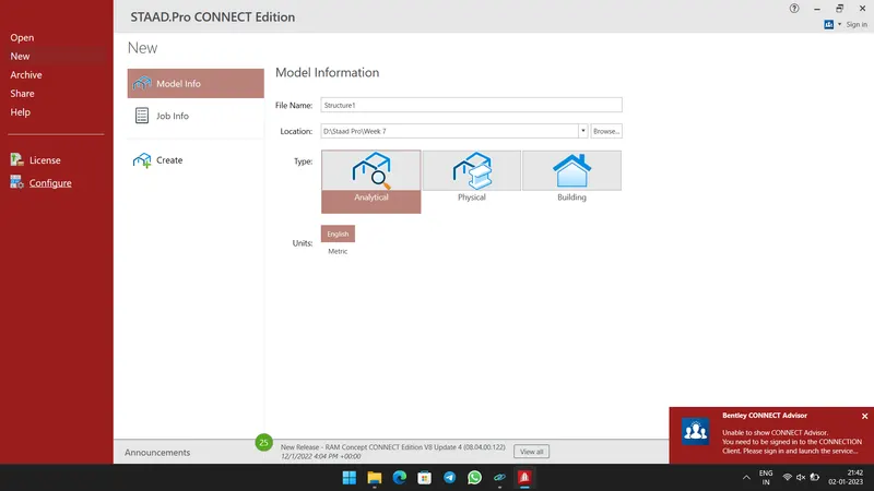
- Open STAAD.Pro CONNECT Edition software.
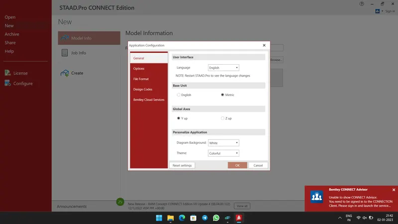
- Then Click Configure option to set basic Unit and Global Axis as shown below.
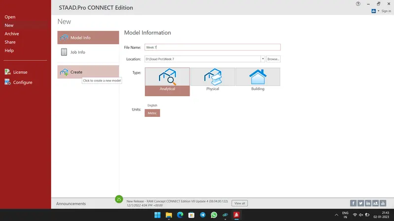
- Now give File Name and select the location to save the Project.
- And Click Create option. A Workspace opens.
Step 2:-
- Now create a node to draw the Truss members.
- In Nodes window create a node with the coordinates of (0,0,0).
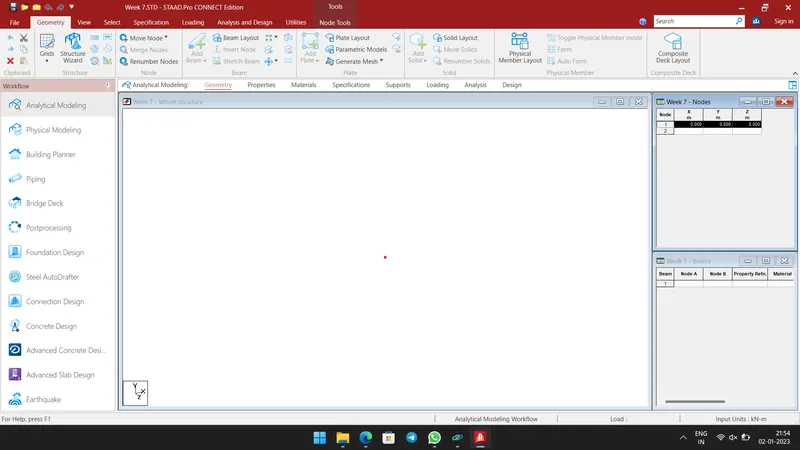
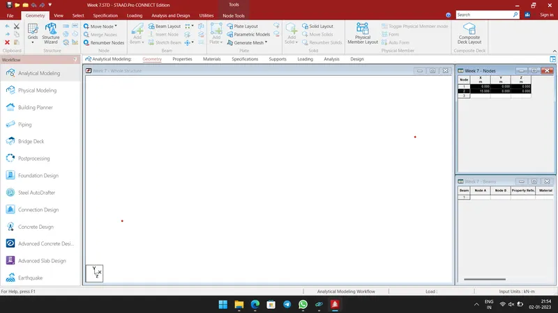
- Again create the node at coordinate (15,0,0).
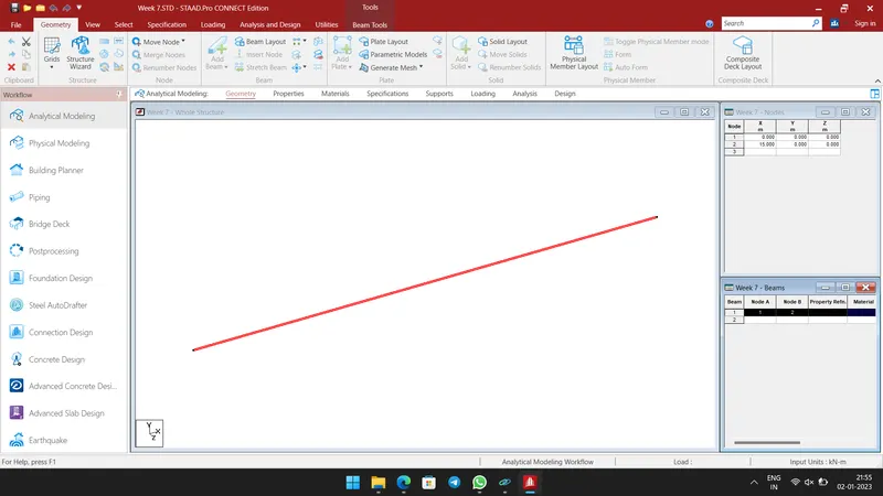
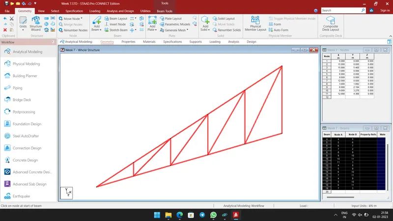
- Now join the nodes 1 & 2 by creating the beam using Beams window.
- For given slope 20°, height of Truss arrived as 5.45955m.
- Then insert node at height 5.45955 (15,5.45955,0)
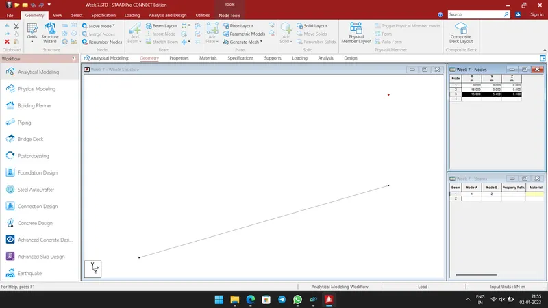
- Then draw beams between the nodes (2-3) and (1-3) as shown below.
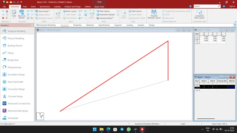
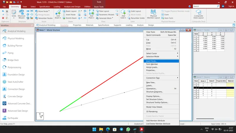
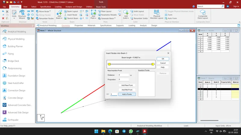
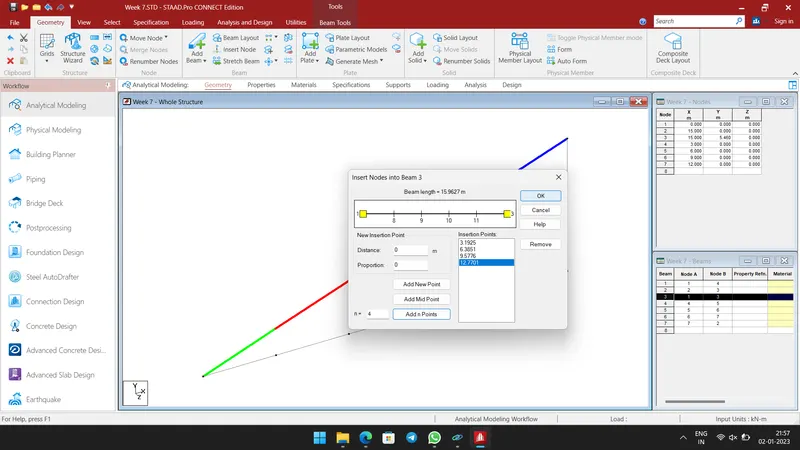
- Now split the Beam 1 and Beam 3 into 5 parts as shown below.
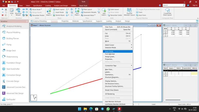
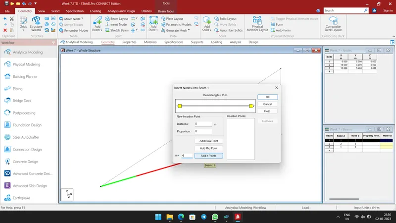
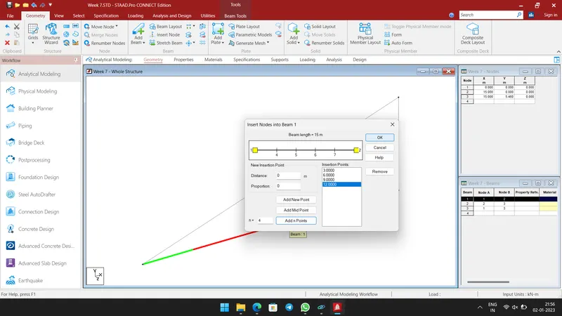
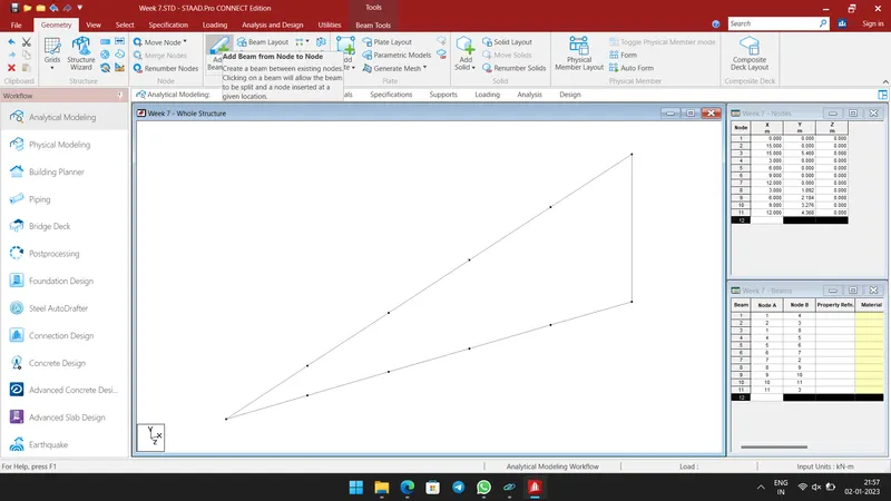
- Now form Truss by connecting the nodes in the Beam 1 & Beam 3.
Step 3:-
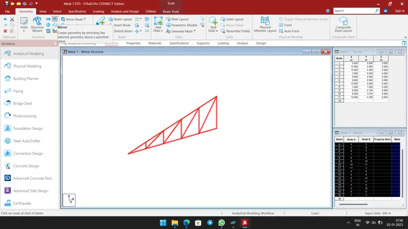
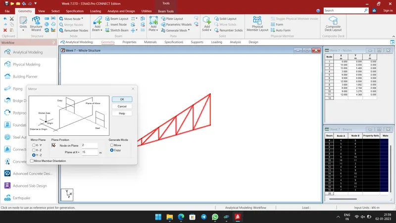
- Select Mirror Option to create the Truss on another side.
- Then choose the node to Mirror along the aixs.
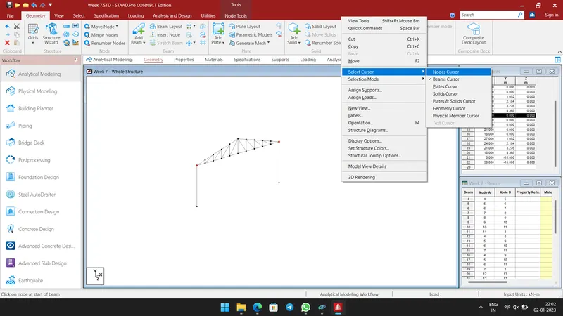
- To create column, Right the mouse cursor and choose Nodes cursor.
- Then select the end nodes by Holding Ctrl Button in the Keyboard.
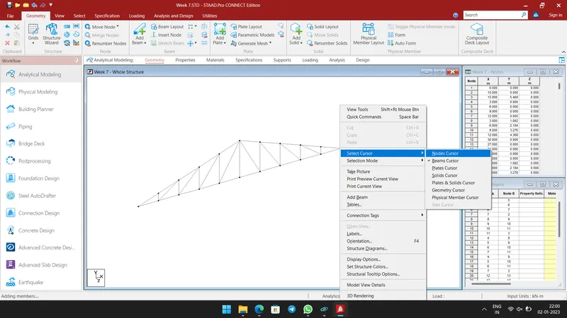
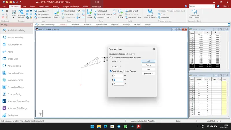
- Then Copy the Nodes and paste it in Y-Direction of distance -15m.
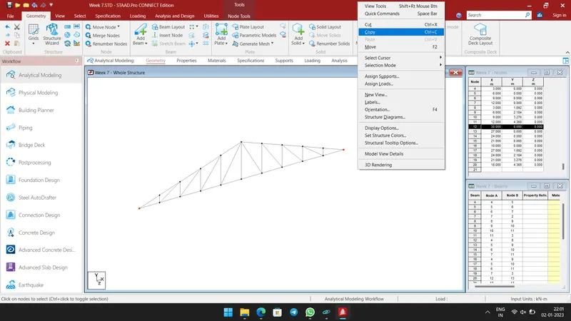
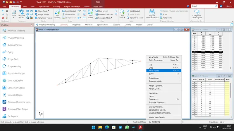

- Now Nodes are created.
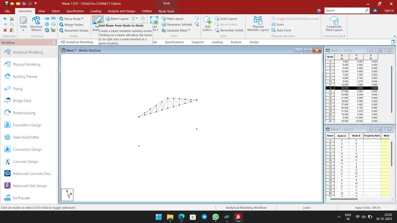
- Connect the nodes to form external column.
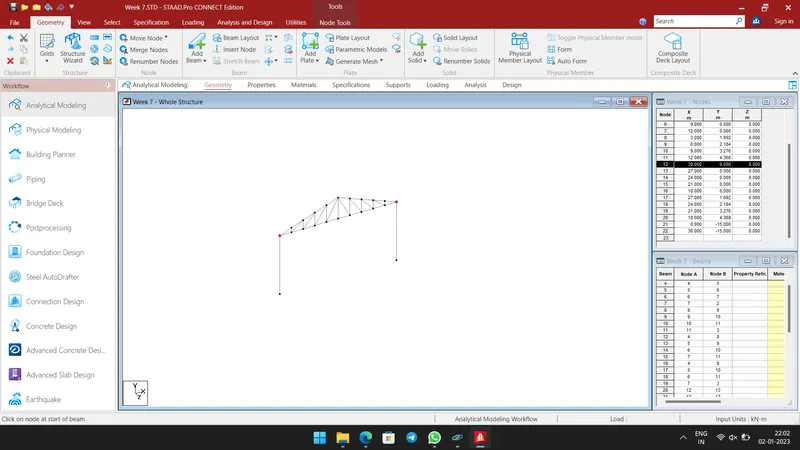
- To draw Primary beams select and copy the column base nodes to 5m along Y-Direction as shown below.
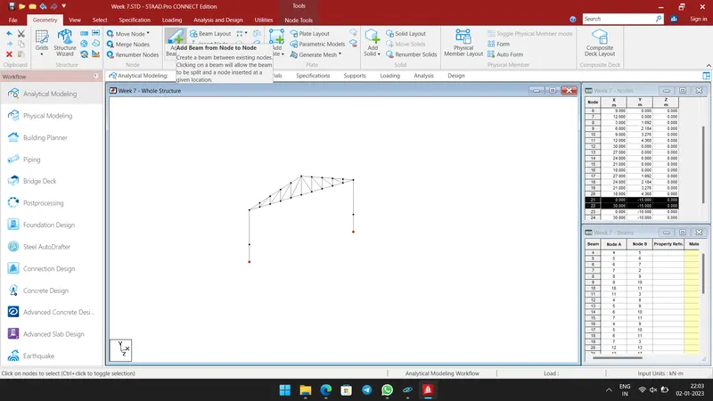
- Then connect the nodes to create Primary beams.
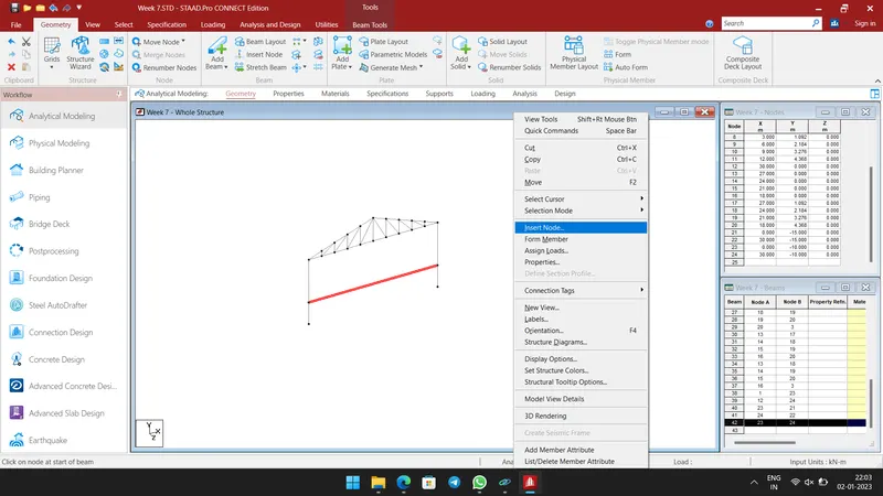
- Now splitup the beam to 5 parts to draw the Supporting column.
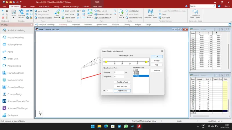
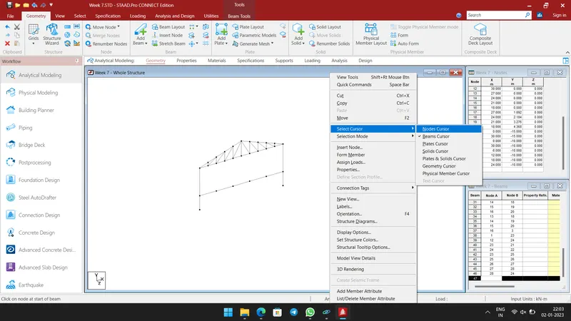
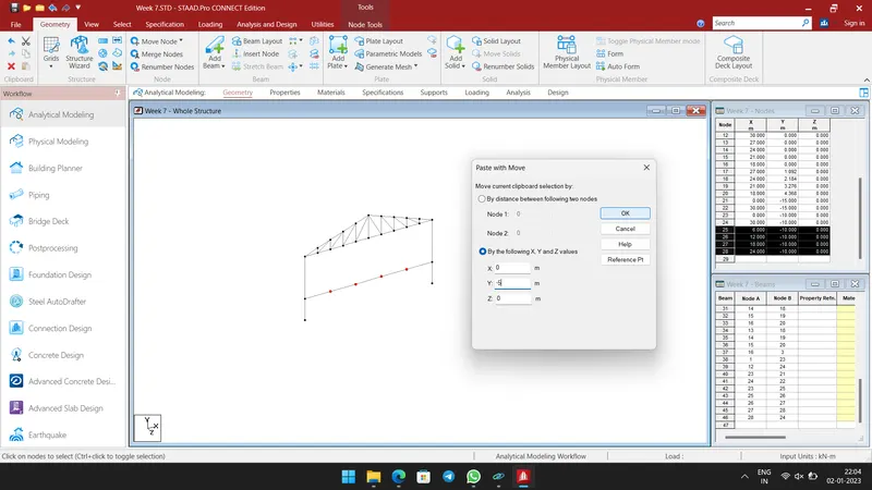
- Now select and copy the nodes selected in the Figure to draw the supporting column.
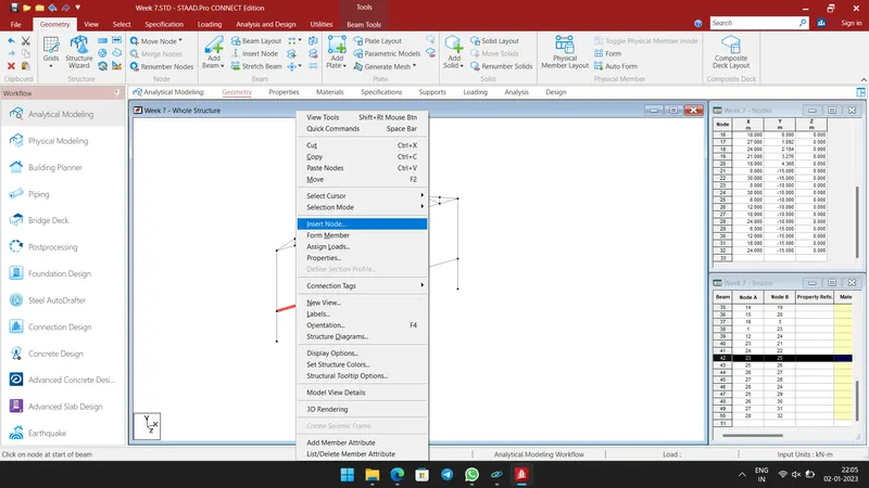
- Then create nodes for Secondary beams by Insert 3 nodes between each column.
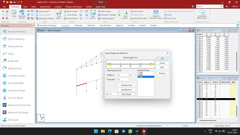
Step 4:-
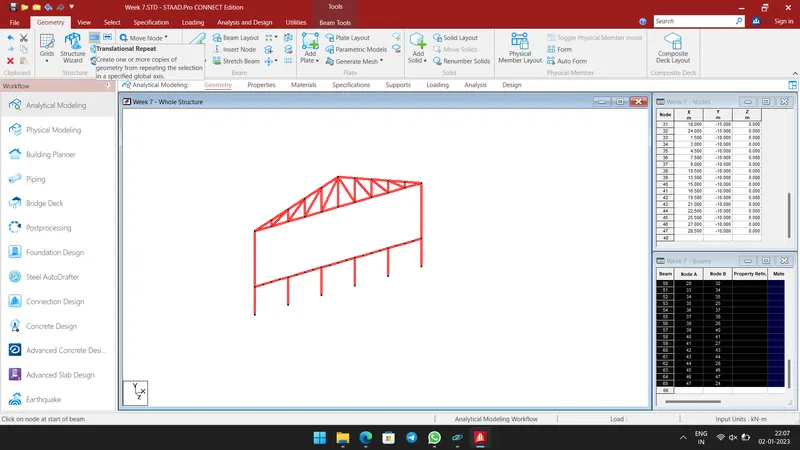
- Select the Translational Repeat tool to form the Shed model.
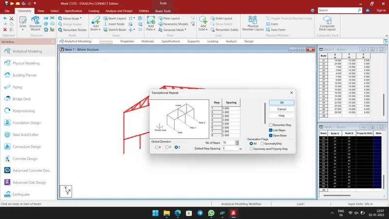
- Then click Z-Direction, No. of Steps as 10 and Spacing as 5m.
- Check the Link steps and Open base as shown below.
- Thyen click Ok.
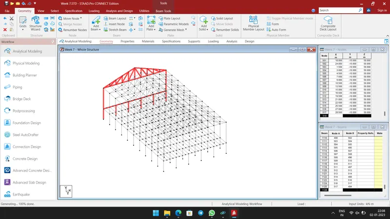
Result:-
- Pratt Truss was created successfully using STAAD Pro software.
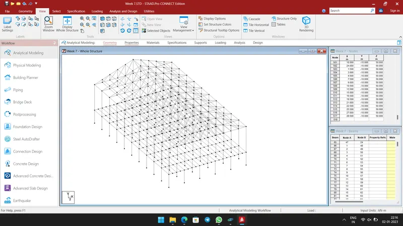
2. Applying Specification and member property for modelled structure
Apply beam steel specification as mentioned below.
- Columns - ISMB 500
- Truss -Top & Bottom chord – ISA 110x110x12, Diagonal member – ISA 75x75x8
- Purlins – ISMC 150
- Tie Beam – ISA 120x120x10
- Floor Primary beams – ISMB 300
- Secondary beams - ISMC 150
- Floor beam supporting columns – ISMB 300
- Assume bottom of the main column as Fixed support & intermediate floor beam supporting column as pinned
- Orient the Angle sections by applying Beta angle.
Aim:-
To apply Specifications and Member property for modelled structure in Question 1.
Procedure:-
Step 1:-
- Now select Properties option in Workflow.
- Then click Section Database option to view the Section available in the STAAD Pro itself.
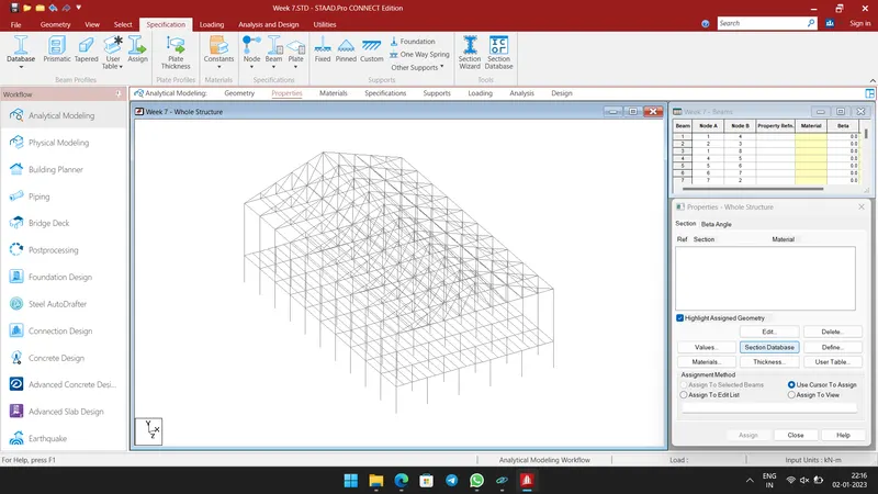
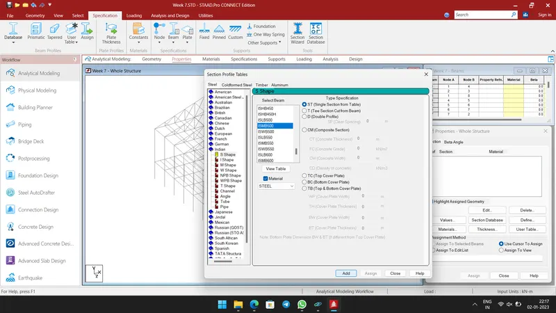
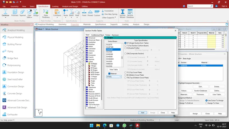
- Then select Indian sections and click S Shape to choose ISMB 500 and ISMB 300.
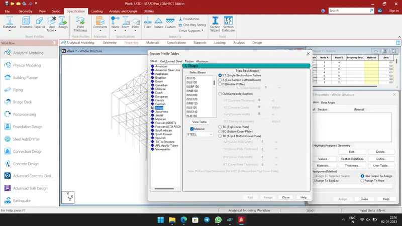
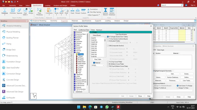
- Choose ISMB 500 and click Add.
- Similalry Add ISMB 300 as shown below.
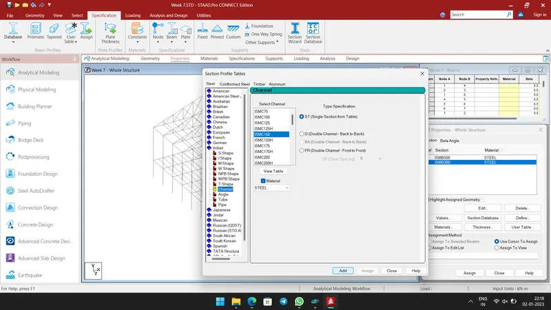
- Then select Channel section to choose ISMC 150 section and click add.
- Now select Angle section to choose ISA 120x120x10, ISA 110x110x12 and ISA 75x75x8 sections and click add.
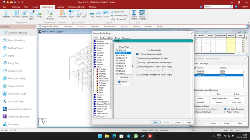
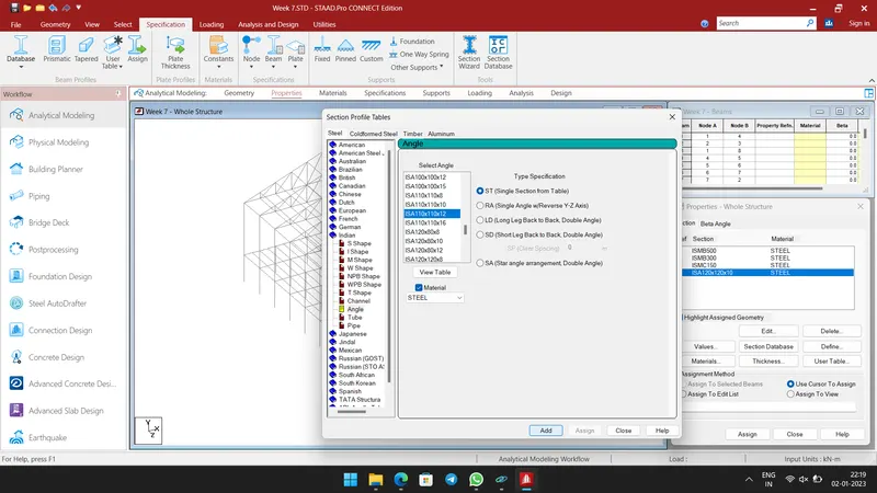
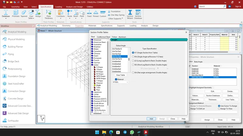
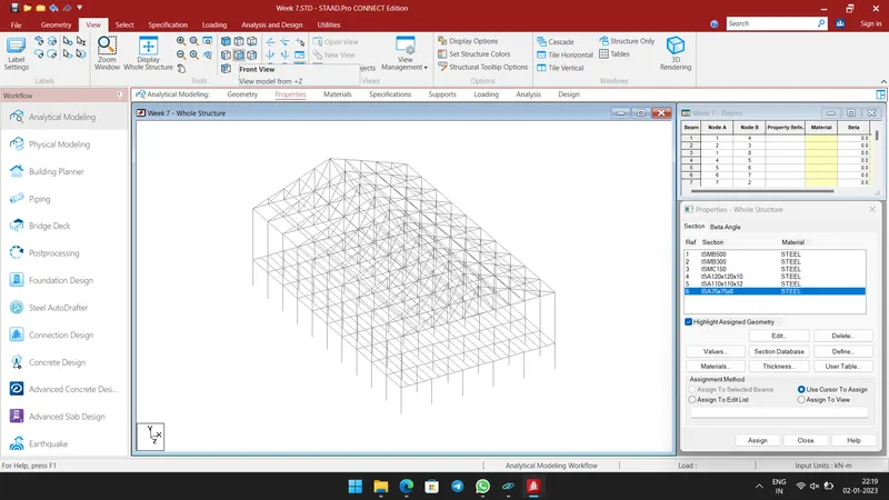
- Now we have added all section required.
Step 2:-
- First select External Columns and Open in new View.
- Assign ISMB 500 section as shown below.
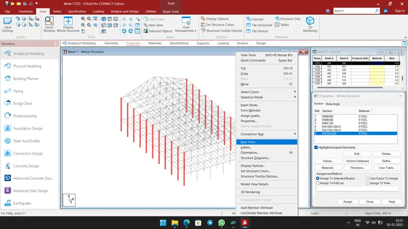
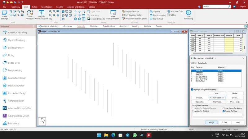
- External Columns are assigned as R1.
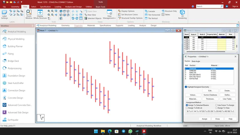
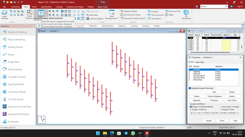
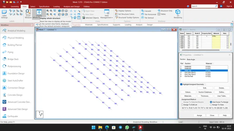
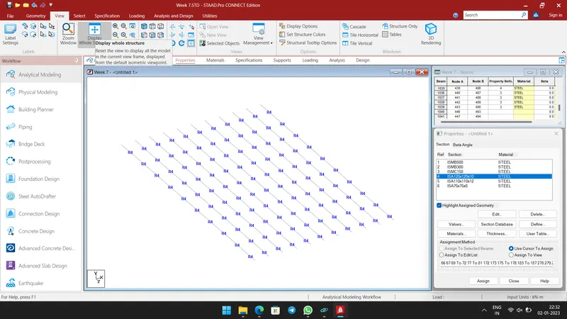
- Now Click Display whole Structure to view full structure again.
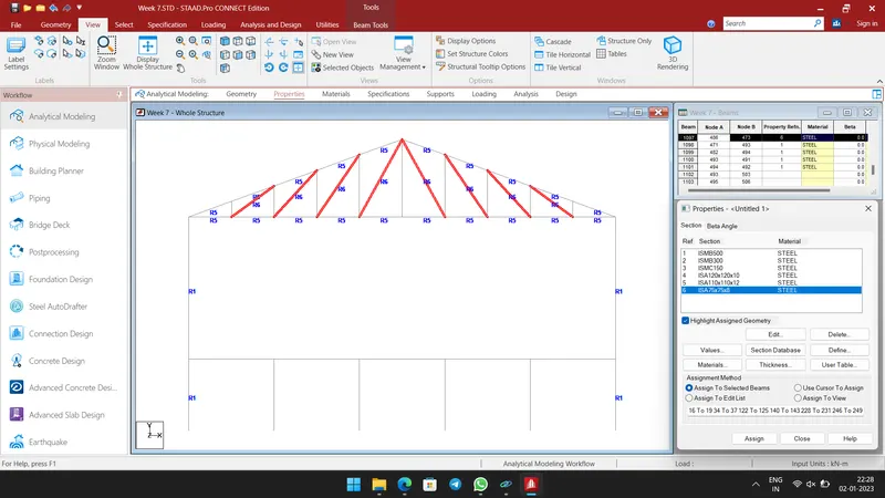
- Similarly select and create New View for Truss Members as shown below.
- And Select Top and Bottom cord.
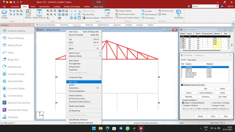
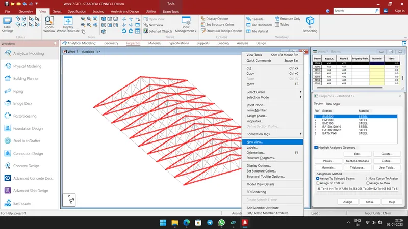
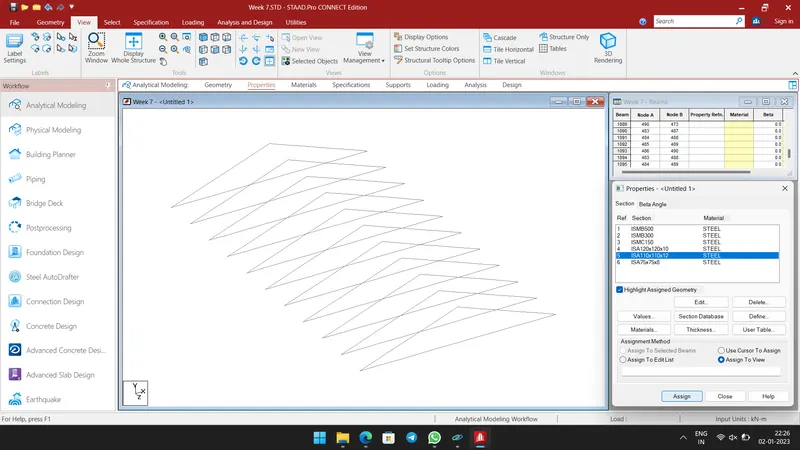
- Now assign ISA 110x110x12 section.
- It is assigned as R5 as shown below.
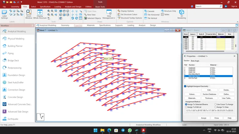
- Similarly assign all Members by selecting right sections.
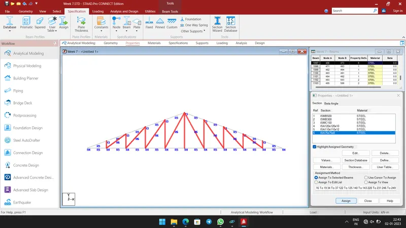
- Roof Frames are assigned as ISA 75x75x8 (R6).
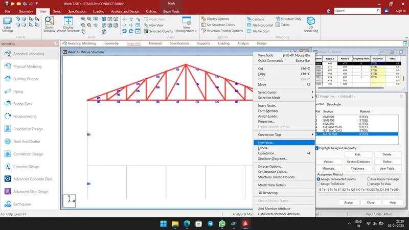
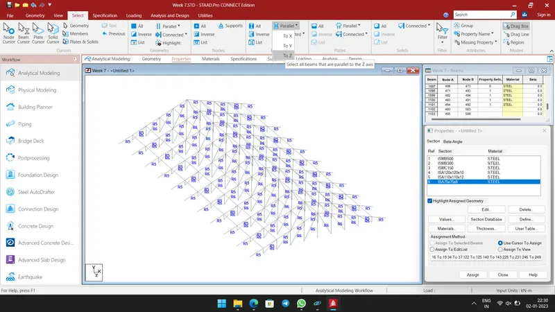
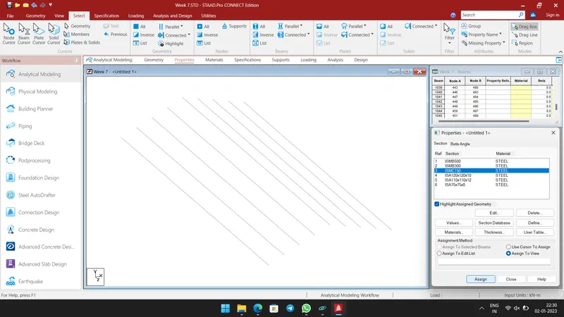
- To select Purlin members easily, go to Select Tab and click Beams parallel to Z Axis.
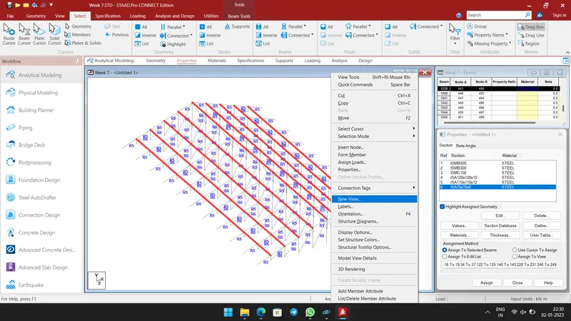
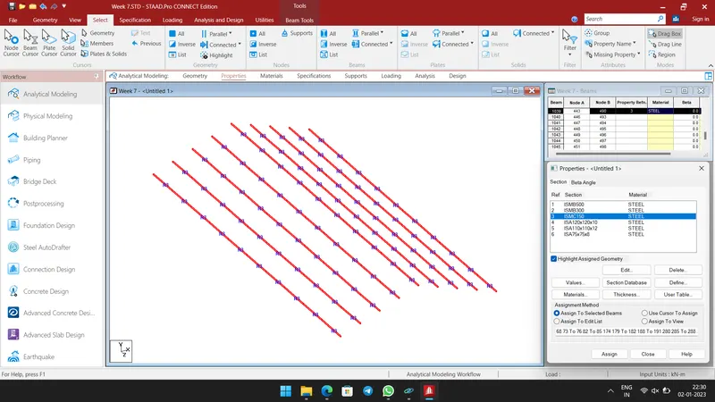
- Purlin selected.
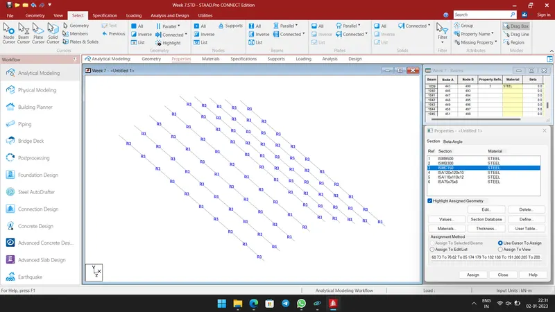
- Then assign the Section ISMC 150 as R3.

- Now select the and open the New view of Bottom Truss.
- Then select Beams parallel to Z Axis from Select Tab.
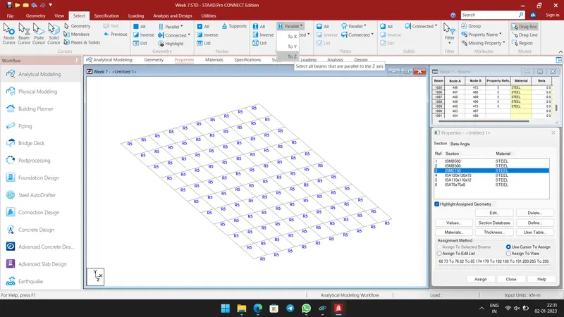
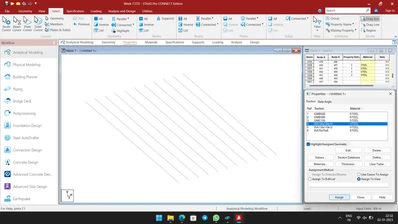
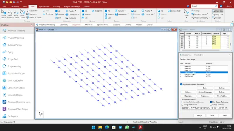
- Tie beams selected. Now assign ISA 120x120x10.
- It is assigned as R4.
- Now Select the Beams and open in the New view.
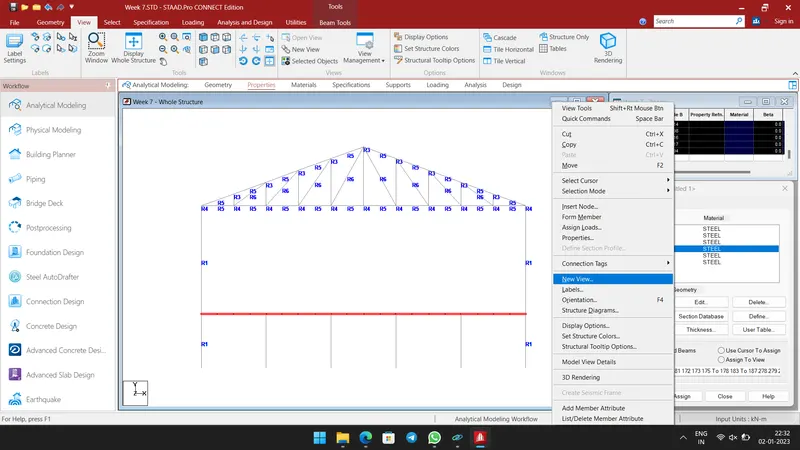
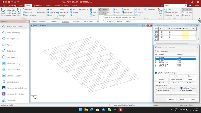
- Then select all primary beams and assign ISMB 300.
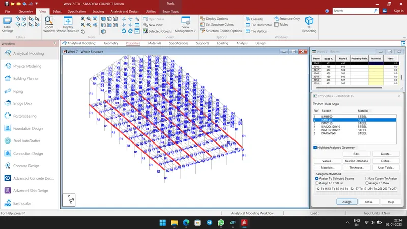
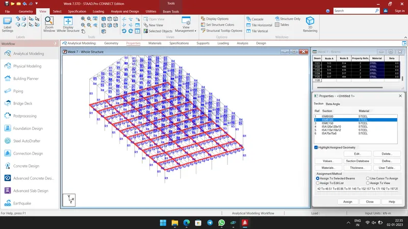
- Primary Beams are assigned as R2.
- Then select all secondary beams and assign ISMC 150 (R3).
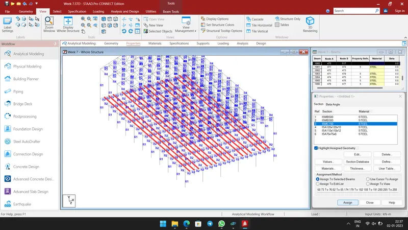
- Now Select all Supporting columns and assign ISMB 300 as R2.
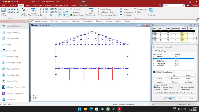
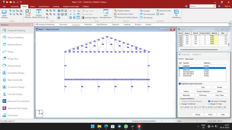
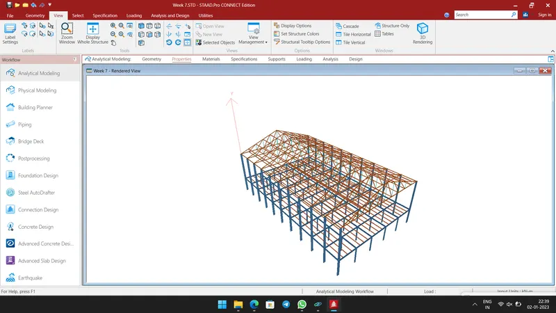
- Now we can see the sections assigned by choosing 3D Rendered Display.
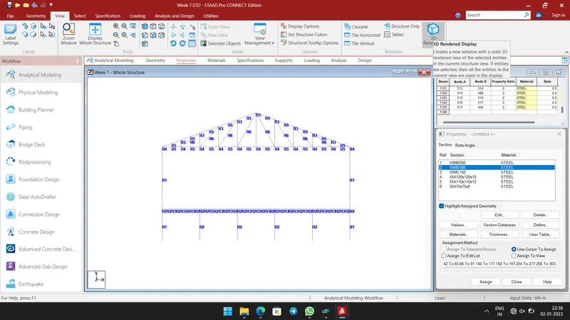
Step 3:-
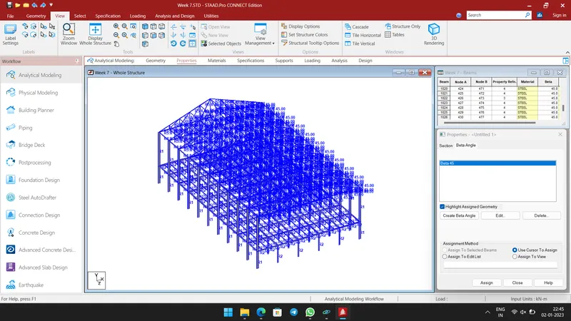
- To align Angle section in correct rotation.
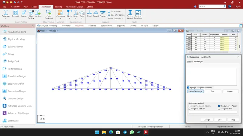
- Select Beta Angle in Properties Window.
- Then click Create Beta Angle as shown below.
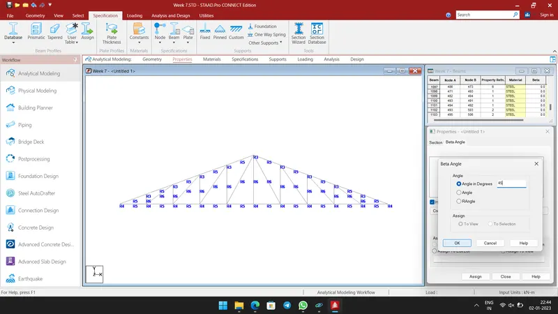
- Set angle as 45°.
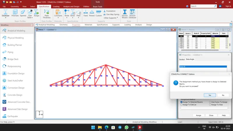
- Then select the Angle sections and assign Beta Angle.
Step 4:-
- Go to Supports tools in Workflow.
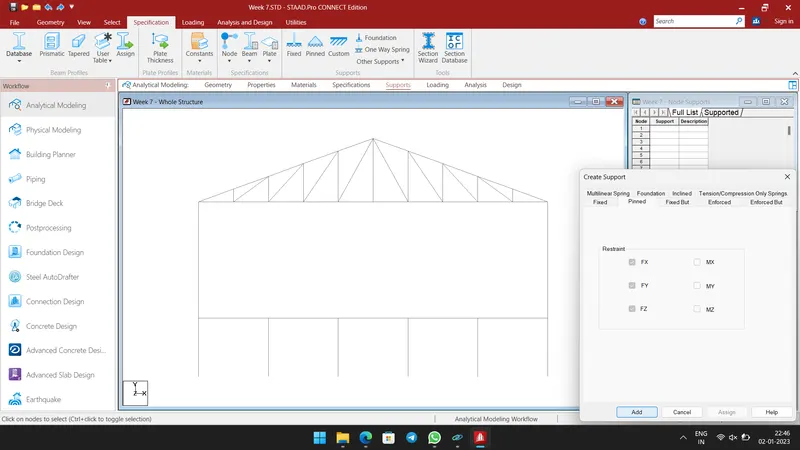
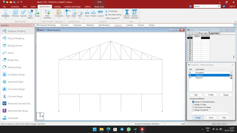
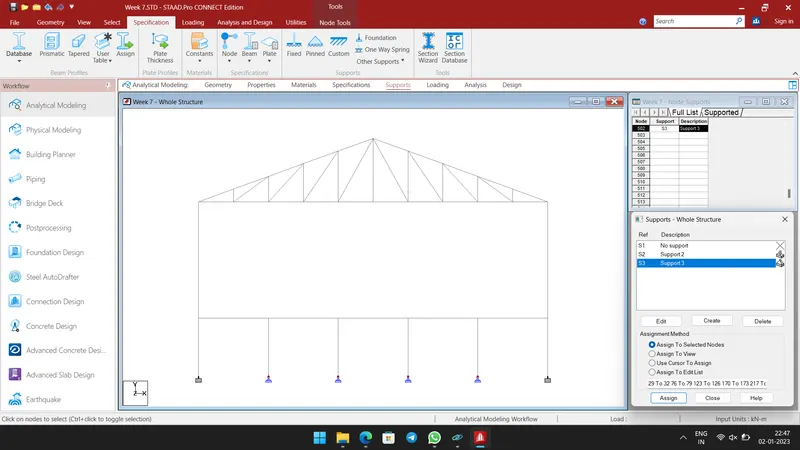
- Then create the Fixed Support for External Column and Pinned Support for Inetrnal supporting Column.
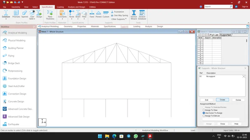
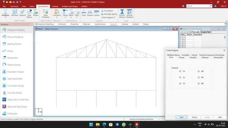
- Then Select nodes and the Fixed Support
- And assign the support to external Columns.
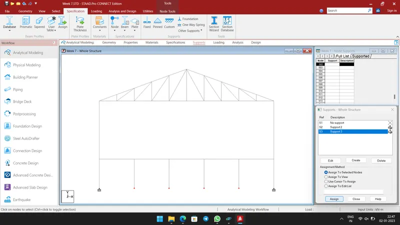
- Again select the internal column nodes and assign Pinned Support.
Result:
- Specifications and Section properties assigned to the members successfully.
3. Creating a group exercise.
Form group for following members
- External column
- Internal columns
- Roof Frames
- Top chord of the Truss
- Primary Beams
- Secondary Beams
Aim:-
To create a group for the above members of created model in Question 1.
Procedure:-
Step 1:-
- Go to Utilities Tab, select Groups option.
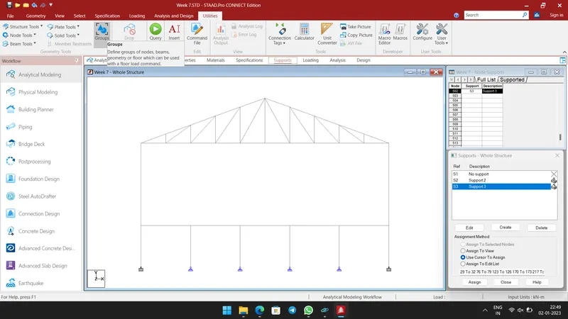
- A new popup window opens.
- In that window, Type the name as External Column and select Type as Beam.
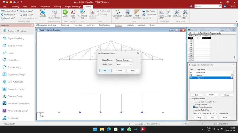
- Then select the External columns and Click Assoiciate.
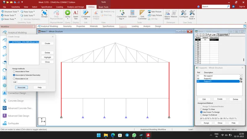
- Then Click Create to add another group.
- Then do the same procedure.
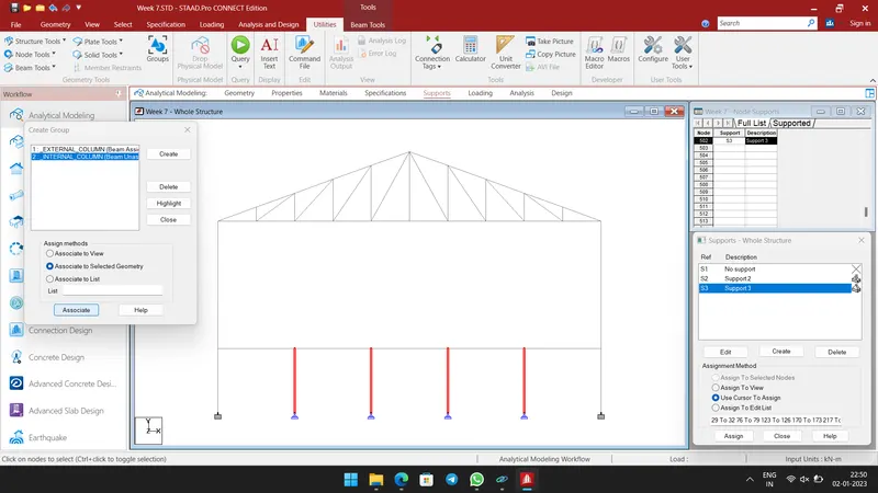
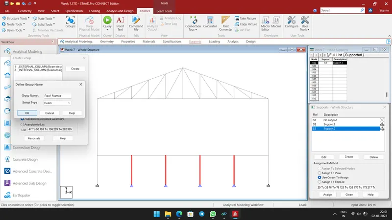
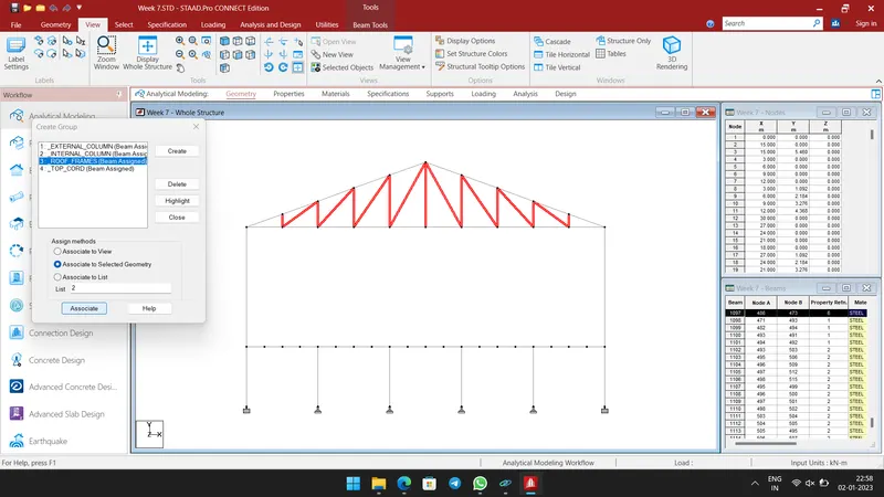
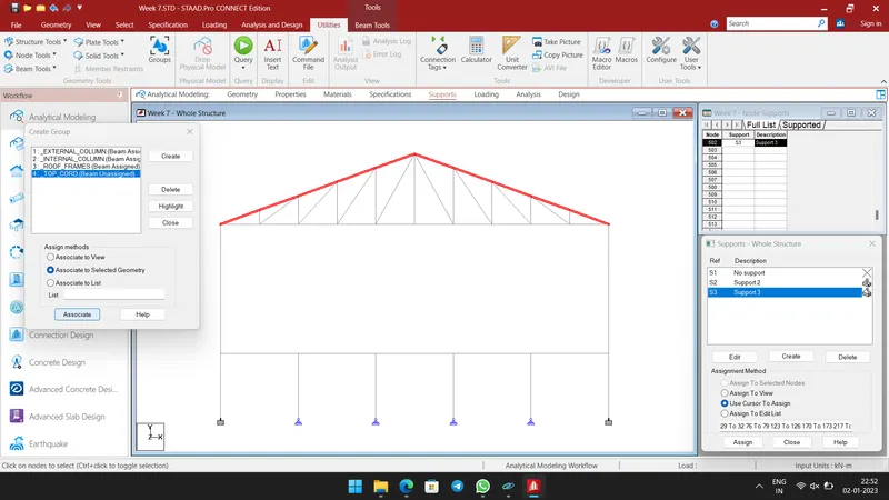
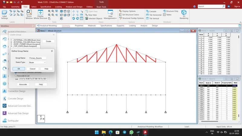
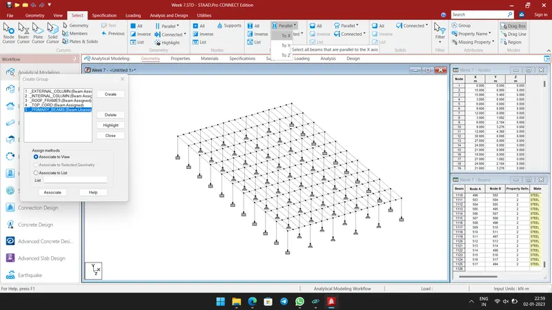
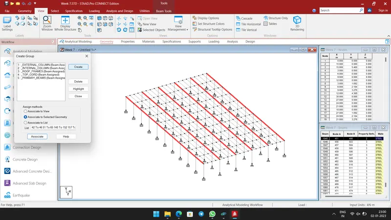
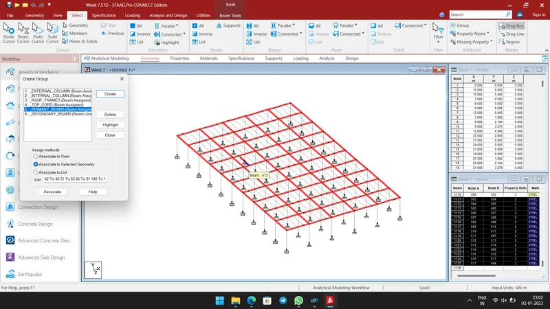
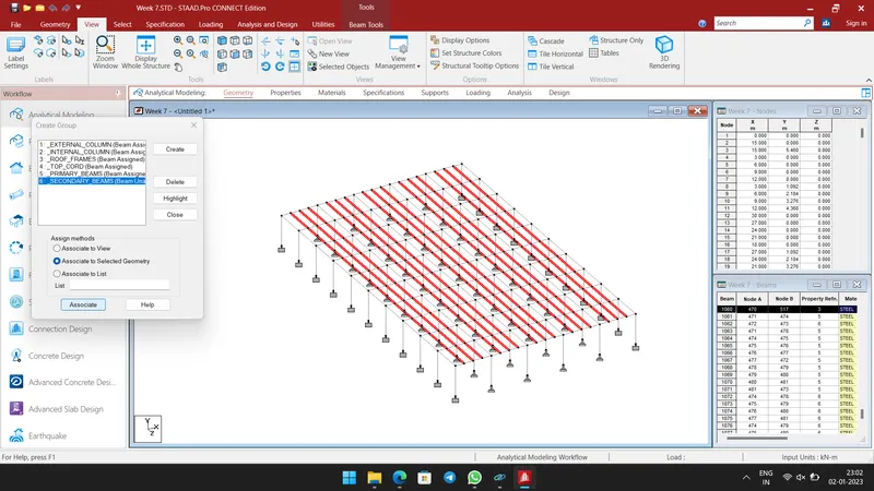
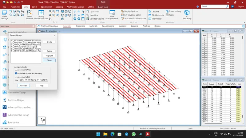
- All members are grouped.
Step 2:-
- To check the Groups are associated well, click Highlight option as shown below.
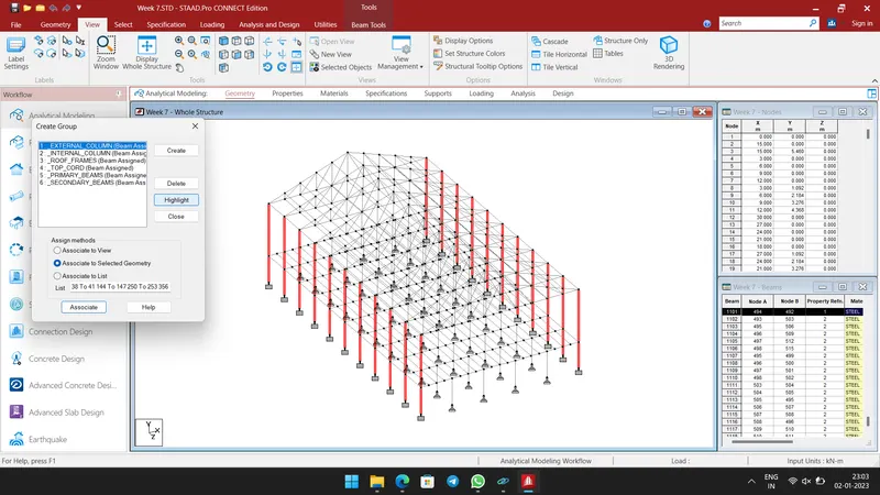
External Columns
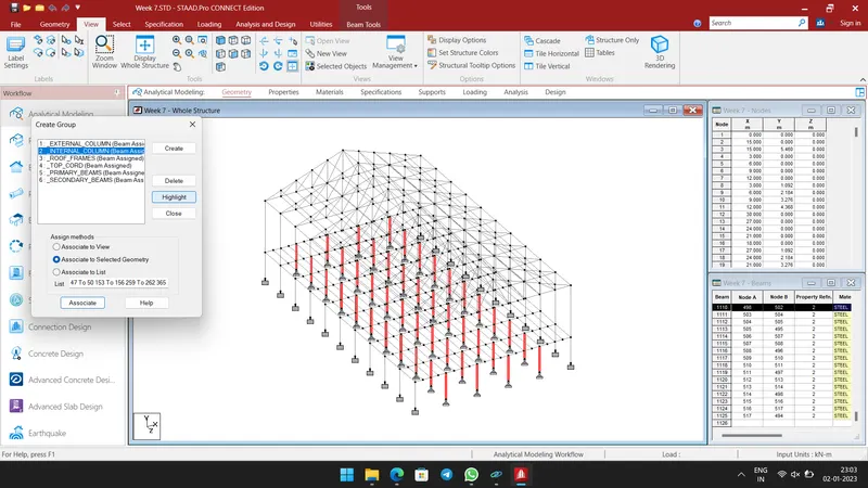
Internal Columns
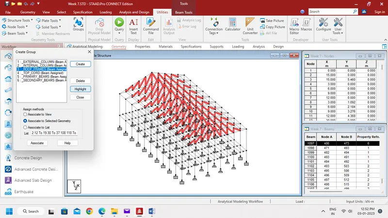
Roof Frames
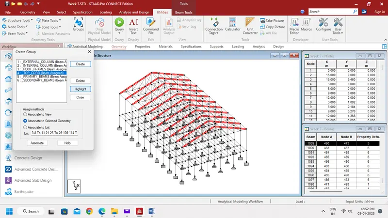
Top Cord
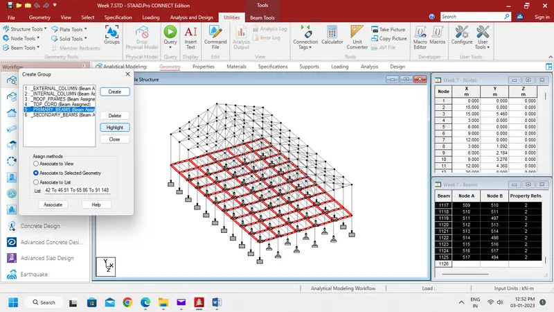
Primary Beams
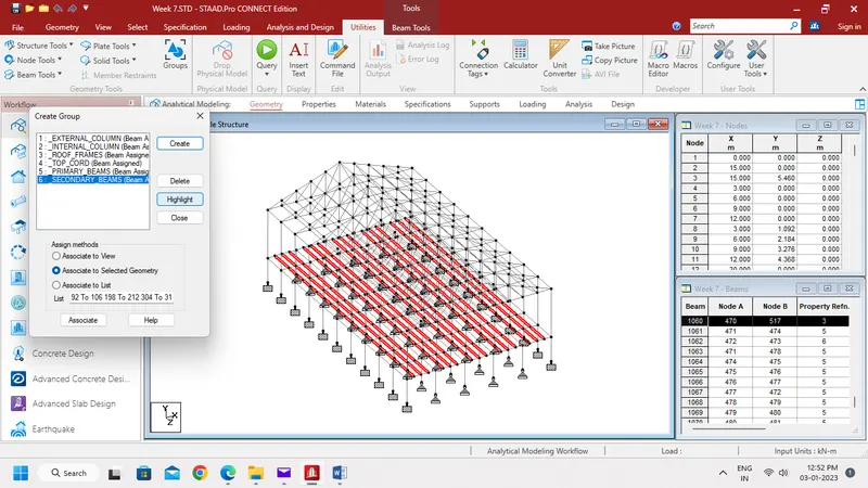
Secondary Beams
Result:-
- All the members are grouped and highlighted successfully.