Week 7- Base Unit Design Challenges 2
Aim: To design a Base Unit for the units designed for the above challenges with all weldments for the given Car Panel and to make sure that all the 5 Panels given in the CAD data are fully constrained with the 3-2-1 principle.
Introduction:
Base Unit
A base unit is the unit designed to mount all the other units, such as the pin,clamp and rest units for example, of the tool and also the other components or parts necessary for a tool like the valve box, trunking cable path and such will be mounted on the base unit.
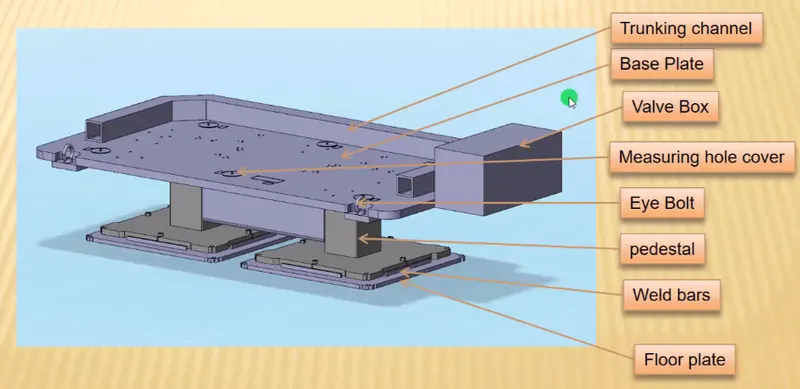
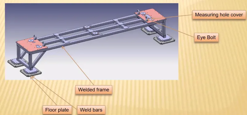
The typical parts of a base unit are as follows:
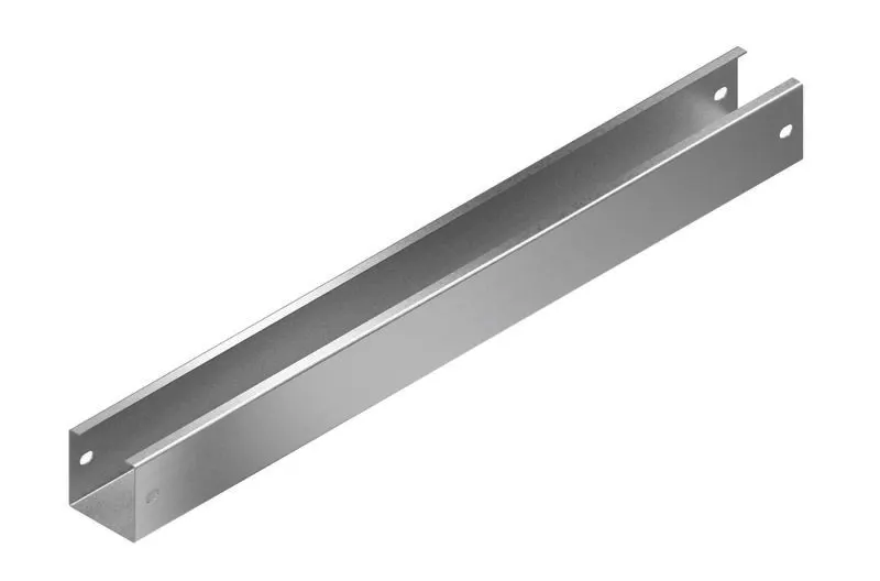
- Trunking Channel: A trunking channel is a duct which accommodates all the pneumatic and electrical hoses and wires for the various units of the tool.
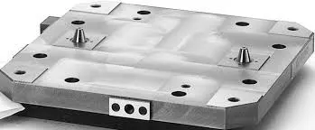
- Base Plate: Base plate is a machined plate of 25-40mm thickness made of steel and aluminum, onto which the required holes are drilled to mount the individual units like the clamp unit, pin unit, rest unit etc of a tool.
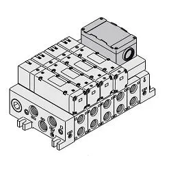
- Valve Box: Valve box is a standard part which will accommodate all the pneumatic valves for the respective units.
- Measuring Hole Cover: This is the plate that is used to cover or protect the holes that we use as our reference for the remaining holes on the fixture from dust and other foreign particles.
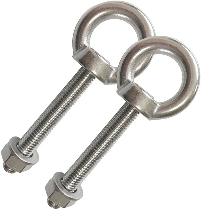
- Eye Bolt: Eye bolts are used for the transporting of the tool with the help of lifting hooks. Fork lift holes are provided in some cases to accommodate for that way of transportation.
- Pedestal: A pedestal is a part of the base unit that connects the base plate to the floor plate. A pedestal is a standard part in general and in certain cases it can be a welded frame integrated with the base unit. Pedestals can be of different sizes and height depending on the requirement as this depends on the size of the base plate and the load it will have to take. They can also come with different inclination for the respective use cases.
- Weld Bar: Weld bar is a plate along the sides of the base plate of the pedestal. Weld bars are to be used to weld the positions permanently once the levelling of the base plate is done.
- Floor Plate: The floor plate is grounded to the floor with fixed bolts on the floor. Floor plates are also called foundation plates and they have to maintain a clearance of 10mm between the pedestal base plate and the floor plate and this clearance will be used by the levelling screws to level the entire tool.
3-2-1 Prinicple
The 3-2-1 principle of location is used to constrain the movement of workpiece along the three axes XX, YY and ZZ. This is achieved by providing 6 locating points, 3 pins in base plate, 2 pins in the vertical plane and 1 pin in a plane which is perpendicular to the first two planes. The degree of freedom is the defines the ability of a body to move. Every body has 12 degrees of freedom or 12 possible movements and these twelve are broken down into 6 translational degrees of freedom and 6 rotational degrees of freedom. The 3-2-1 method is the fundamental principle for all types of fixture design.
Consider a body in a 3-axis coordinate system where we have the X, Y & Z as the respective axes. The image below shows the body in this coordinate system
From this we can infer that the 6 translational degrees of freedom are about:
+X, -X, +Y, -Y, +Z, -Z.
The 6 rotational degrees of freedom:
- Clockwise about X-axis (CROT-X)
- Anticlockwise about X-axis (ACROT-X)
- Clockwise about Y-axis (CROT-Y)
- Anticlockwise about Y-axis (ACROT-Y)
- Clockwise about Z-axis (CROT-Z)
- Anticlockwise about Z-axis (ACROT-Z)
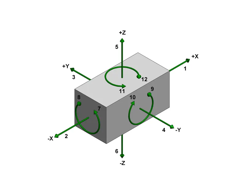
What this infers is that this body in space will have translational motion about any of the 3 mutually perpendicular axes in both directions and this provides the body with its 6 translational motions. The body can also rotate, clockwise or anticlockwise, about any of these 3 axes and this is what gives the body its 6 possible rotational motions.
We use locators, which are devices to establish and maintain the position of the workpiece properly to ensure that the work done it is accurate and repeatable.
The holding fixture used in an assembly operation often follow the 3-2-1 locating scheme to position parts. The first locators position a part in the primary plane, the next 2 locators then position the part in the secondary plane and final locators fixes the part in the tertiary plane and hence we lock the part in all its degrees of freedom.
The image below shows how the locators fix the part in all possible motion.
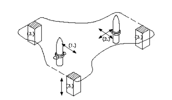
It can be observed in the image above that the 3-2-1 principle was followed to fix the workpiece. The first 3 pins placed at the bottom on the base plane (a plane parallel to the X & Y axis) restrict the rotation of the component about the X and Y axis. It also limits the downward movement of the component along the Z-axis.
The next 2 pins are in a plane parallel to the plane containing the X & Z axes. It prevents the rotation of the component about the Z axis and the movement of the body along Y axis in direction.
In the previous challenges we have applied the 3-2-1 prinicple on the main car panel and succesfully arrested its motion in all possible directions. In this challenge we go about applying the same principle on the minor panel which account for 4 out of the 5 panels that was provided to us.
Design:
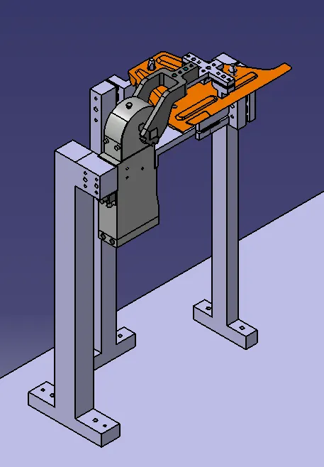
Locating the first panel with 3 clamps and 2 pins
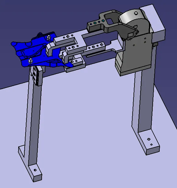
Locating the second panel with 2 clamps and 2 pins
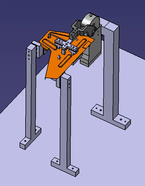
Locating the third panel with 3 clamps and 2 pins
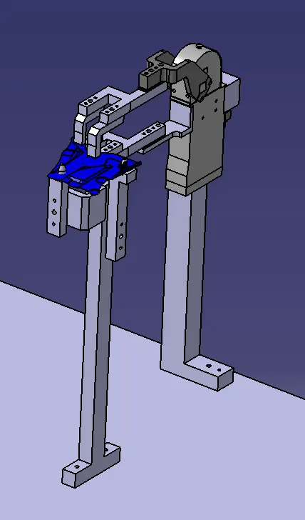
Locating the third panel with 2 clamps and 2 pins
Final Design: The image below shows how the 3-2-1 locating principle was applied on all 5 panels at once.
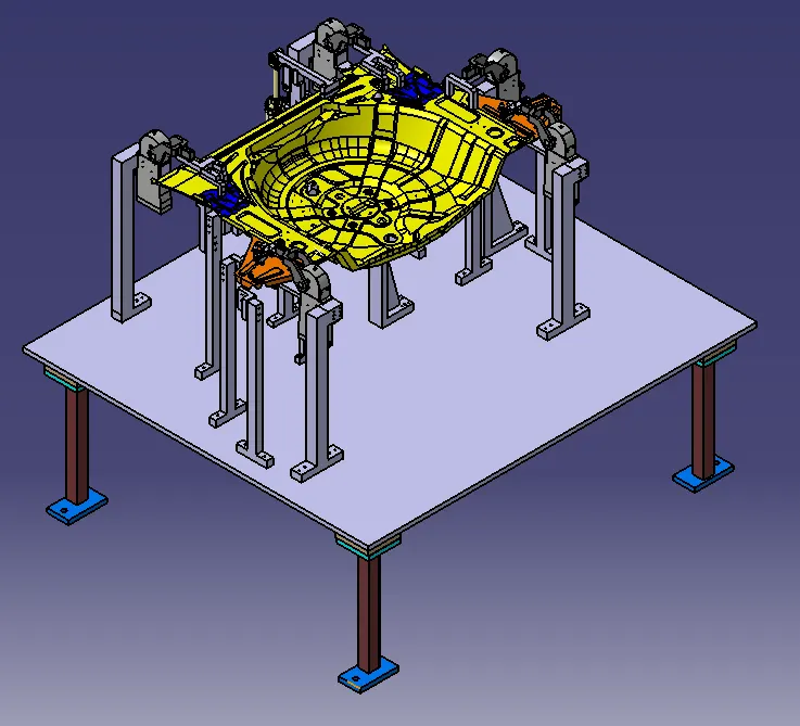
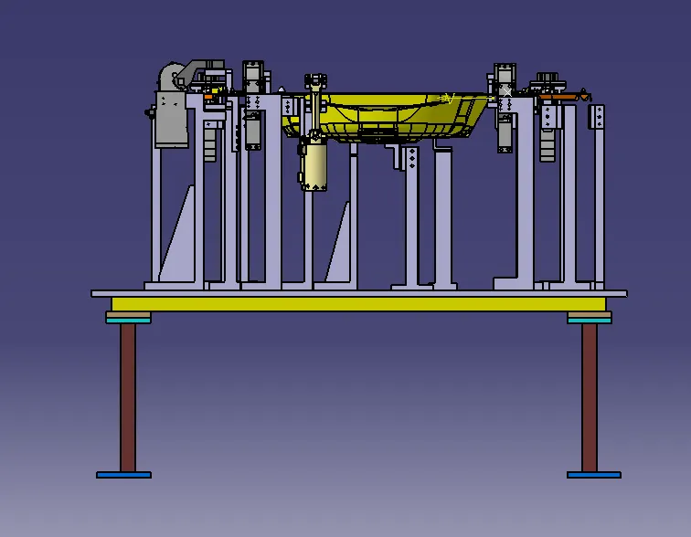
Conclusion: All panels provided have been arrested using the 3-2-1 prinicple and the required base unit has been created as per the design requirements