Week 7:- Base Unit Design Challenges 1
Challenge-7 week-7 Base unit design Challenge-1
Q1. What is the base unit? What are the typical parts of the base unit?
A base unit is used to secure all other assembled units, such as clamps, pins, and swivels, to it. Other parts necessary for operation include the : valve box, Trunking channel, base plate, measuring hole cover, eye bolt, pedestal, weld bars, and floor plate also provided on the base unit. To provide air to the inlet of all pneumatic cylinders, a trunking device with valve box is employed. The base unit also supports a trunking cable path. The following figure depicts the many components of the base unit.
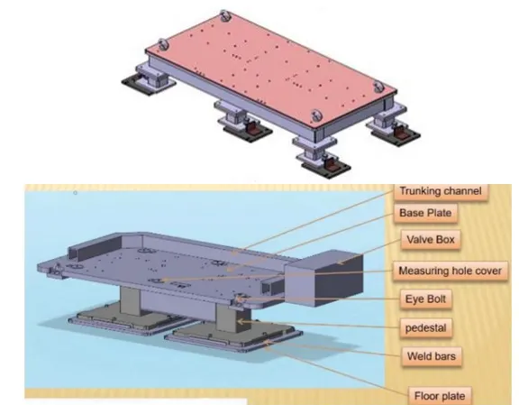
Different parts of base unit:
Base plate: - The base plate is a steel and aluminium plate with a thickness of 25 to 40 mm. A number of holes have been drilled in the base plate to serve as mounting points for the clamp unit, pin unit, and so on. A Rectangular Base plate with dimensions of 1100 X 1900 X 30 is created. A base plate size covers all units with its outer peripheral individual opening and must be designed with respect to the BCS co-ordinate system.
Floor Plate:- is grouted to the floor with stationary bolt on the base floor plates are called floor plate.
Pedestal:- is used to connect the base plate to the floor plate, as shown in the figure above. Depending on the size and height of the fixture, the pedestal can be a standard or custom part. Standard pedestals come in a variety of inclinations. The number of pedestals for a fixture can vary depending on the size of the base plate for load distribution. A standard pedestal can be of various heights and sizes.
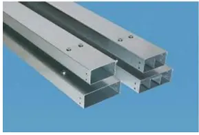
Trunking channel: - is a duct that accommodates all the electrical and pneumatic connections (cable and pipes) for units of the tool.
Valve box:-it is a standard part which contains all the valves for pneumatic units.
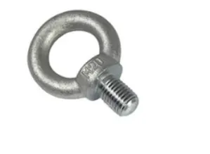
Eyebolt:- Eye bolts are used to lift the assembled fixture for transportation from one location to another or for loading/unloading. Hooks are inserted into them. For example, we typically use M20 bolts bolted to the base plate. Lift holes are sometimes provided for transportation purposes.
Q2. What are the points need to consider while designing a base unit?
- Working Height - This is determined by the type of manual or robotic welding fixture. For manual fixtures, we must consider the working height of 850-1100mm, depending on the
worker's working height, and the standard of a specific country will apply. - The clearance between the pedestal base plate and the floor plate should be kept at 10mm. This clearance will be used for levelling by the levelling screws. The base unit should include some openings for free movement of workers as well as cover all of the units within it.
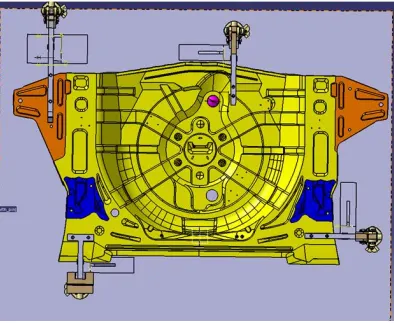
- The size of an eyebolt for lighting holes on a base plate is determined by the weight. For lifting holes on the base plate, four eye bolts are usually chosen. You must also choose the location of the eye bolt so that the ropes/belts used to shift the structure or entire fixture do not damage any units (rest, clamp, or locating units nearby).
- The fixture's base unit must be strong enough to allow for as little deflection as possible. The deflection of a fixture is caused by welding forces and clamping of the workpiece.
- The base unit should not vibrate, so it should have enough mass to prevent vibration and other distribution, as well as consider the flatness of the base plate.
- The base unit's outer periphery, including the opening, should cover all of the units. From the top, there is enough space at all boundaries.
Q3. What is a dump unit?
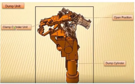
In some cases, getting to the panel is difficult and cannot be fixed with a simple unit. To correct this, a dump unit can be used to complete the operation. To perform such operations, a dump unit may have more than one cylinder. The first cylinder dumps the assembly containing clamps, Mylar, and pins, and this assembly then performs the necessary operations. In this unit, we should ensure that we can remove the panels while the panel is operating. A slide cylinder or a clamp cylinder can be attached to a dump unit. In the case of a dump unit, cylinder validation is critical because the weight may be too heavy for the cylinder to dump.
Q4. What are the points you need to consider while designing a dump unit?
Dump units are used when we cannot use normal units like clamp units, pin units etc. Due to some space constants. For designing this unit one should consider the fallowing cases:-
- It contains the dump unit's cylinder, which will be the heavier part in all units; the riser and blade should be strong enough to support the cylinder and all units.
- In this case, we can use any cylinder that meets our needs. Both clamp and hinge cylinders can be used.
- The total weight of the assembly should be as light as possible. As a result, less force is required to push and pull it in order for it to perform the required operation.
- The opening and closing time of clamp should be less as much possible for the smooth operation.
- The parts should be designed with the open state of the unit in mind. The parts should not fall to another unit while the unit is open.
- The Design parts should be small in size but can do their functions effectively.
Q5. What is a slide unit?
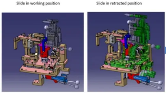
It is used when there is limited space and we do not have enough space to design different special units to assemble. In those cases, the slide unit is used. Slide units are used to position the fixtures, weld gun, units, and robots in order to perform the operation. For various operations, various slider units such as CNC, hydraulic, and manual are available. Depending on the application, it can also be classified as a horizontal, vertical, or angular slider.
Q6. What are the points you need to consider while designing a slide unit?
Sliding unit consists to complex unit, so while designing it one should consider the following points:
- There are different kind of guide rail is available in the standard form. One should consider it based on the assembly.
- The suitable locking and stopper mechanism must be provided to avoid in accident while it is at open or retract position.
- The two end limits must be designed properly with sensor to detect the position.
- Shock absorbers are used to be both extended and retracted conditions.
- Stroke length must be selected based on the available space.
*************************************************************End of Report**************************************************