Week 7:- Base Unit Design Challenges 1
1)
Base Unit: A base unit is a foundational structure designed to mount all other units of a tool, such as clamp units, pin units, rest units, and other necessary components like pneumatic valve boxes and trunking cable paths.
The base unit is essential to the fixture as it supports all other components. Its design varies depending on the panel, clamp system, location system, and other factors.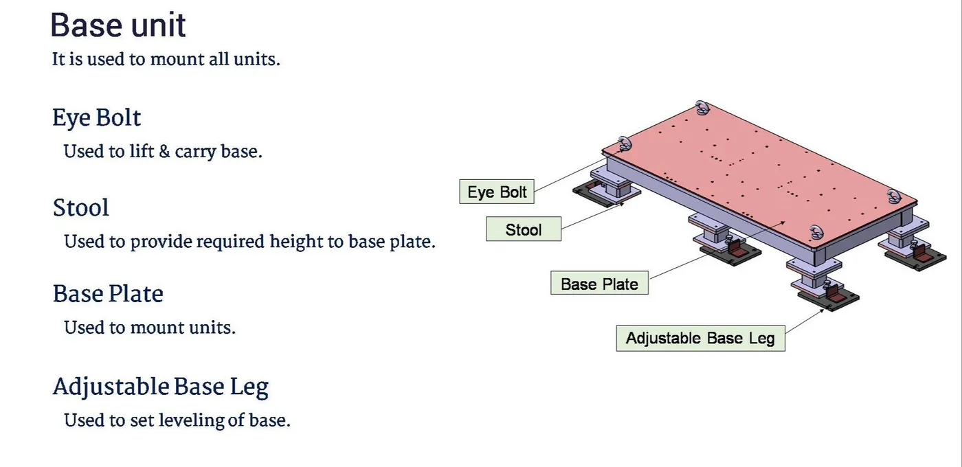
Typical Parts of the Base Unit:
1. Base Plate:
- A plate with a thickness ranging from 25 mm to 40 mm.
- Contains numerous holes for mounting clamp units, pin units, and other components.
2. Pedestal:
- Connects the base plate to a floor plate.
- Can be a standard or custom part, depending on the fixture’s size and height requirements.
- Available in various heights and inclinations.
- The number of pedestals can vary to ensure proper load distribution.
3. Trunking Channel:
- A duct for carrying electrical and pneumatic connections (wires and pipes) for the tool’s units.
- Typically has a thickness of a few millimeters.
4. Valve Box:
- A standard part containing solenoid valves for pneumatic units.
- Manages air pressure inlets and outlets for the pneumatic fixtures.
- Includes pressure inlet cables within the trunking channel to protect them during operation.
5. Eyebolt:
- Used for lifting and transporting the fixture by inserting hooks into them.
- Commonly, M20 bolts are used and are bolted to the base plate.
- Sometimes, forklift holes are provided for transportation.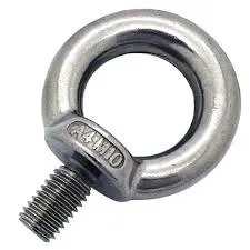
6. Floor Plate:
- Also known as the foundation plate, it is grounded using fixed bolts.
- There should be a 10 mm clearance between the pedestal base plate and the floor plate.
- Weld bars are used after leveling is done with leveling screws.
- Steel plates along the sides of the pedestal’s base plate, known as weld bars, are used to position the pedestal permanently.
2)
Key Considerations for Designing the Base Unit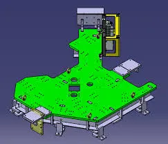
1. Working Height:
- Depends on whether the fixture is manual or robotic.
- For manual fixtures, the working height should be between 850-1100 mm, taking into account the average height of workers in the specific country (e.g., higher in the US, lower in Japan).
- For base structures made with a base plate and a tubular structure, the height can range from 100 mm to ~250 mm.
- To achieve the desired working height, additional leg structures with top plates welded to the tubes may be needed.
2. Handling and Fabrication:
- Consideration of how large base plates or welded structures will be handled during fabrication and transport.
- Ensure flatness, especially for long base sizes, to maintain structural integrity.
3. Eyebolt Selection and Placement:
- Choose eyebolt sizes based on the weight of the base unit.
- Typically, four eyebolts are provided for lifting.
- Eyebolt placement should be such that ropes or belts used for shifting do not damage nearby units (rest, clamp, or location units).
4. Base Plate or Welded Structure:
- Decide between a fabricated base or a simple plate based on the size and weight of the components.
- Fabricated bases are often made of square or rectangular tubes with a plate on top.
5. Dowel Holes for Alignment:
- Most OEMs provide four dowel holes at the corners, marked with X, Y, and Z coordinates on small aluminum plates.
- For longer bases, some OEMs place dowel holes at intervals of 500 mm for better alignment.
6. Structural Strength:
- The base unit must be strong enough to minimize deflection caused by welding forces and workpiece clamping.
7. Mass and Vibration:
- The base unit should have sufficient mass to prevent vibration and chatter during operation.
8. Construction and Assembly:
- The base unit should be built from simple sections allowing other units to be fastened with screws or welded as needed.
- Permanent parts of the fixture can be welded, while parts requiring frequent changes should be screwed.
9. Coverage:
- The base unit should cover all the fixture units within its outer periphery, including any openings.
10. Parallelism and Height Adjustment:
- The base unit should be parallel to the floor.
- Include a height-adjusting mechanism to ensure parallelism.
3)
Dump Unit: Overview and Functions
Sometimes, certain panels are difficult to reach and cannot be fixed using simple units. In these cases, a dump unit is used. A dump unit can have multiple cylinders to perform the required operations. The first cylinder dumps the assembly carrying clamp mylars and pins, allowing the assembly to perform its operation. It's crucial that in the open position, the panel can be easily removed.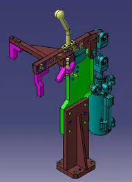
Functions of the Dump Unit:
1. Proper Resting and Motion Restriction:
- Ensures the panel being welded rests properly and restricts its motion during the welding process.
2. Rotation Prevention:
- Prevents rotation of the panel by fixing it with pins, side blocks, or magnets.
3. Clamping Force:
- Provides sufficient clamping force through the cylinder to keep the panel stationary during welding.
4. Shimming for Adjustment:
- Incorporates correct shimming to adjust the panel accurately.
Components and Considerations:
1. Cylinders:
- A dump unit can have a slide cylinder or a clamp cylinder attached.
- Cylinder validation is critical as the weight may be too heavy for the cylinder to handle.
- Calculations are performed to ensure the force exerted by the cylinder can handle the load.
- If the cylinder's force is adequate, it is validated; otherwise, a more powerful cylinder is used.
2. Design Considerations:
- The dump unit design must ensure the panel can be removed when in the open position.
- Proper validation of cylinder capacity to manage the weight of the assembly is essential.
Dump units are crucial for fixing hard-to-reach panels, ensuring proper resting, preventing rotation, and providing adequate clamping force. The design and validation of the cylinders are vital to handle the weight and perform the necessary operations efficiently.
4)
Considerations for Designing a Dump Unit
Designing a dump unit involves careful consideration of various factors to avoid errors that could lead to significant time and financial losses. Here are the key points to consider:
1. 3-2-1 Principle
- Rest Mylars, Pins, and Clamps: Ensure the correct design and placement of rest mylars, pins, and clamps.
- Cylinder for Clamping: Add and verify the functionality of the clamping cylinder.
- Positional Accuracy: The assembly must accurately dump onto the panel to ensure precise resting and clamping, which is critical for the unit’s purpose.
2. Mass
- Minimize Weight: Design the assembly to be as lightweight as possible without compromising strength.
- Material Selection: Use materials like aluminum for the cylinder and steel for other parts to balance strength and weight.
- Factor of Safety: Calculate the mass and add a margin for safety to ensure reliability.
3. Time of Opening and Closing
- Minimize Cycle Time: Ensure that the opening and closing times are as short as possible to reduce idle time and increase efficiency.
- Power of Cylinder: Choose a cylinder with adequate power to handle the assembly’s weight quickly.
4. Cylinder Validation
- Centre of Gravity: Calculate the center of gravity of the moving assembly.
- Longest Perpendicular Distance: Determine the longest perpendicular distance from the vertical line passing through the center of gravity (C.G.) and the pivot center.
- Shortest Distance to Cylinder Line: Measure the shortest distance between the pivot center and the cylinder line.
- Force Calculations: Validate the cylinder by comparing the calculated push and pull forces with the required forces. If the cylinder’s force is insufficient, select a more powerful cylinder.
5. Open Condition
- Clearance Check: Ensure that in the open position, the panel can be removed without any obstruction or fouling with the unit.
By adhering to these points, you can ensure the efficient and error-free design of a dump unit, minimizing potential issues and optimizing the performance of the welding fixture.
5)
Slide Unit: A slide unit is a positioning device used to place fixtures, weld guns, units, and robots into the correct position for subsequent operations. Slide units are essential in applications with space constraints, where designing and assembling separate special units is not feasible.
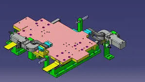
Types of Slide Units:
1. Based on Guide Ways:
- Hardened Guide Ways: These are robust and durable, suitable for heavy-duty applications.
-LM (Linear Motion) Guide Ways: These offer smooth and precise movement, ideal for applications requiring high accuracy.
2. Based on Prime Mover:
- Manual Slides: Operated by hand, suitable for applications where automation is not necessary or feasible.
- Hydraulic/Pneumatic Slides: Powered by hydraulic or pneumatic systems, these slides are used for more forceful or faster positioning requirements.
- CNC Slides: Controlled by computer numerical control (CNC), these slides offer high precision and are used in automated systems.
3. Based on Application:
- Horizontal Slide: Moves horizontally and is used for positioning along the x-axis.
- Vertical Slide: Moves vertically and is used for positioning along the y-axis.
- Angular Slide: Moves at an angle and is used for specific angular positioning requirements.
Applications of Slide Units
Slide units are particularly useful in situations with space constraints, enabling efficient and precise positioning without the need for multiple specialized units. They ensure the optimal use of available space and enhance the flexibility and functionality of automated systems.
6)
Considerations for Designing a Slide Unit
Slide units are complex components that require careful design to ensure proper functionality and reliability. The following points should be considered during the design process:
1. Weight Carrying Capacity
- Guide Rail Selection: Different guide rails have varying load capacities. Calculate the weight of the assembly and select a guide rail that can support this load. Choose a rail with sufficient load-carrying capacity to handle the weight safely.
2. Push and Pull Forces
- Force Calculation: Evaluate the push and pull forces required to move the slide, particularly if it operates at an inclination. Ensure the selected system can generate the necessary forces to move the slide smoothly and reliably.
3. Locking Mechanism
- Stability Assurance: Incorporate a locking mechanism to secure the slide in both the open and retracted positions. This prevents unintended movement during welding, which could damage the panel and compromise positional accuracy.
4. Stopper Blocks
- Position Control: Use stopper blocks to halt the slide at the desired position. This is crucial for applications involving rest mylars and pins, ensuring they stop accurately for proper resting and location. Stopper blocks prevent potential damage by stopping the slide precisely.
5. Sensor Unit
- Position Verification: Include a sensor unit to monitor the slide's position. The sensor sends signals to the PLC, indicating the presence of the unit. This is essential for initiating subsequent operations and ensuring the correct sequence of actions.
6. Stroke
- Stroke Length: Determine the required stroke length based on the work area that needs to be cleared. Ensure the stroke length is sufficient to achieve the necessary range of motion for the slide unit.
7. Open Position
- Interference Check: Verify that the moving parts of the slide do not interfere with other units, such as weld guns or nearby components. Perform a thorough check to ensure there are no obstructions, and approve the design only after confirming the absence of fouling.
By addressing these points, you can design a slide unit that functions effectively, ensuring precise positioning, stability, and reliability in various applications.