Week 7-12-Creation of 1D Connectors Challenge
AIM:
To take the mid surface for all the components after checking the geometrical errors and mesh the mid surface with the given element Quality criteria,for the given Hood model.
GIVEN DATA:
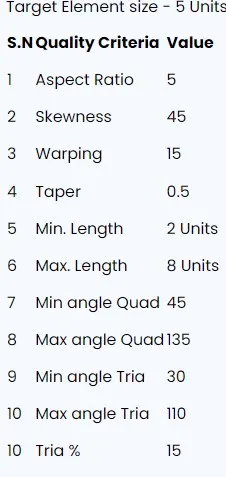
Steps involved in the procedure:
- To check all the geometry error and to fix them.
- Mid surface to be made for all the geometry.
- To generate mesh with the given quality criteria.
PROCEDURE:
- Open the hypermesh software.
- Import the given hood model from the import geometry option
- In hypermesh we can import all the CAD Software file formats like IGES,STEP,etc.
- And we have to do midsurfacing for the component
- to mesh the component within the given criteria.
Given model:
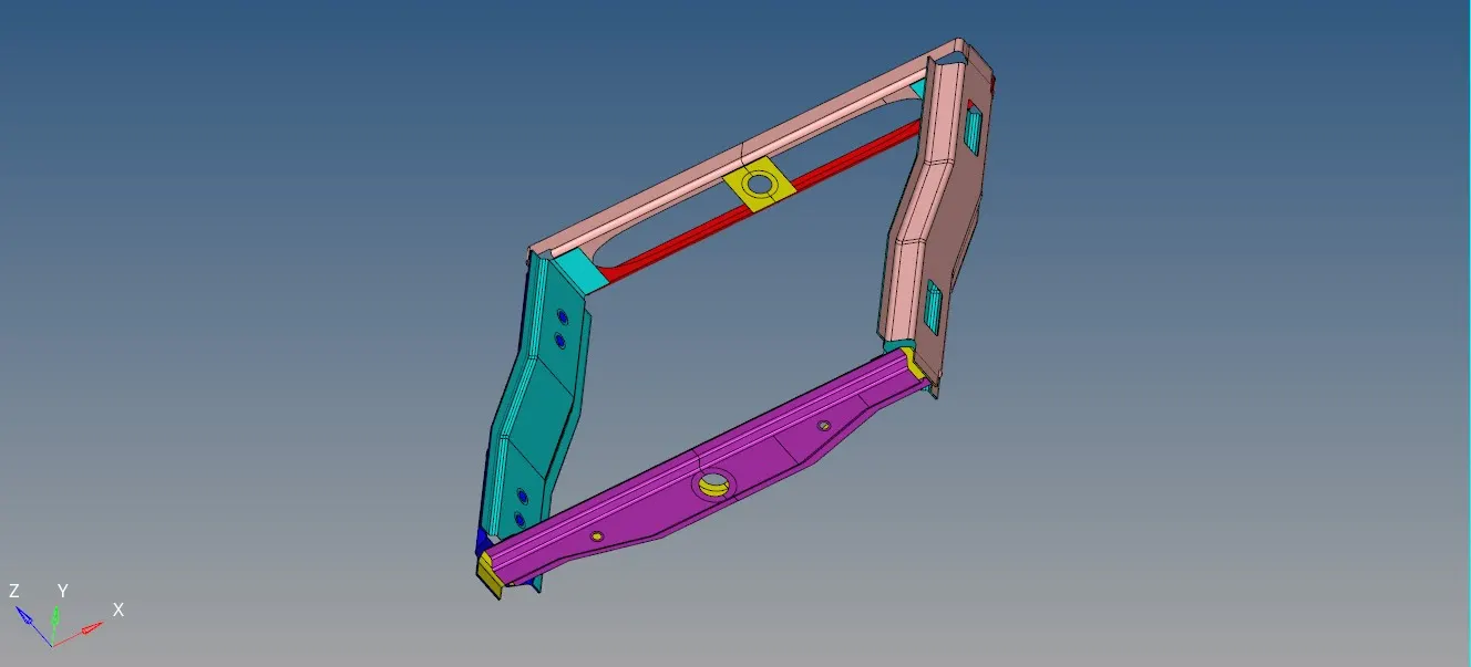
the given model does not require to extract mid surface
we want to add element quality criteria that is given
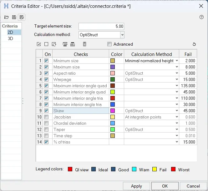
MESHING:
- we can use two types of mesh auto mesh and batch mesh
- Go to 2D or press f12>> Automesh>> select the surface>> provide element length of 5 mm>> choose mesh type as ‘mixed’ >> element to current surface >> select current component as symmetric one >> Keep connectivity >> click on mesh
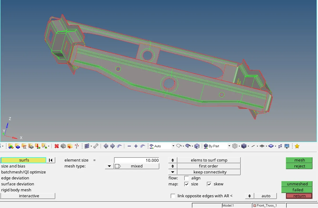
- now we have check for element failing.go to mesh>>check>>element>>quality index.This is the final mesh containing all the components.
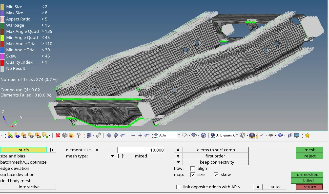
The tria percentage is 0.7%.
CONNECTIONS:
1. Right_Rail_2 & Front_truss_1:- Seam-Quad(angled+capped+L)
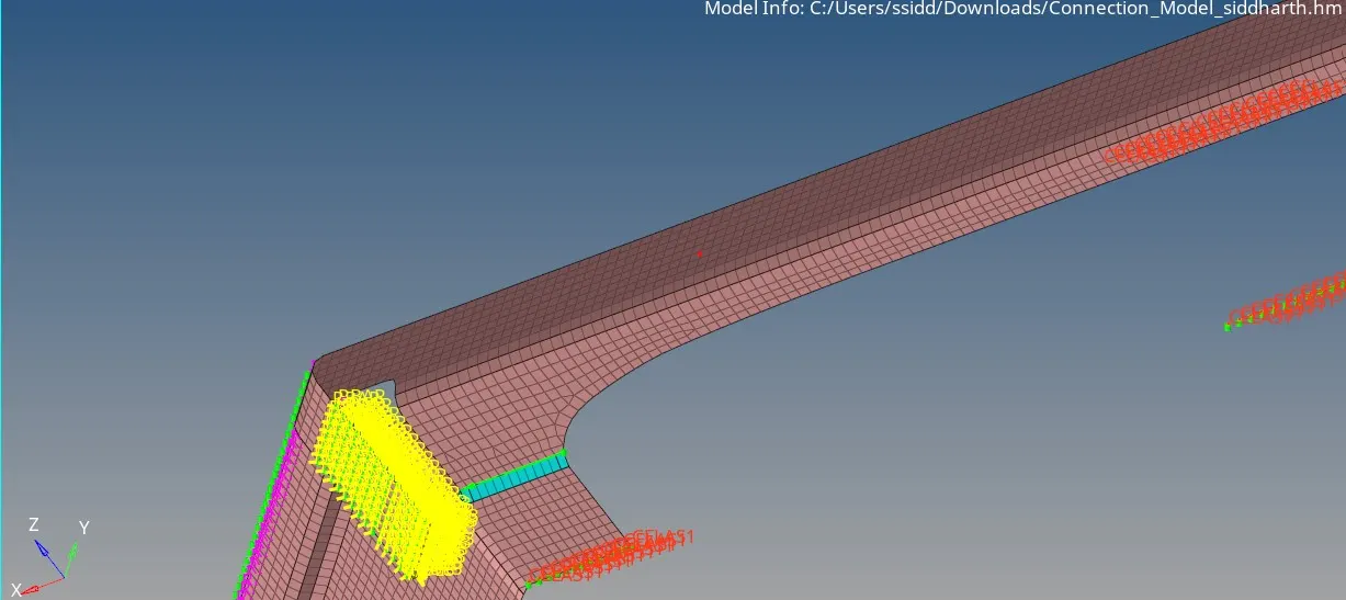
2. Left_Rail_2 & Front_truss_1:- Quad elements
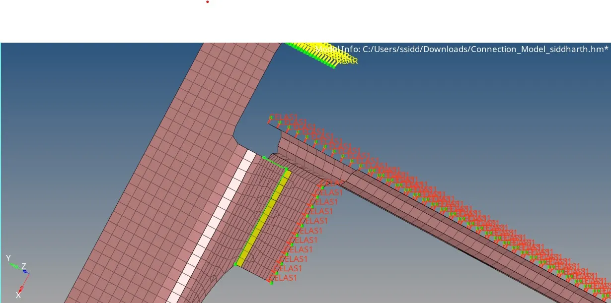
3. Front_truss_2, Front_truss_1 & Right_Rail_1:- Spot weld with 2 Layers and 5 mm Diameter
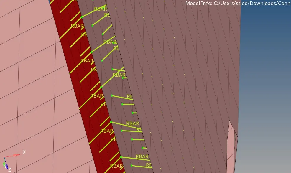
4. Front_truss_2, Front_truss_1 & Left_Rail_1:- Hexa (Adhesive)
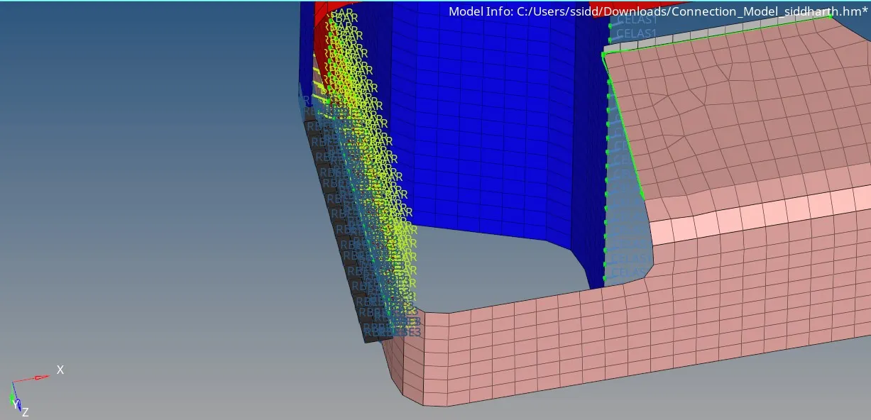
5. Rear_truss_2 & Right_Rail_2:- Bolt Connector
bolt connector method was failing so used node method.
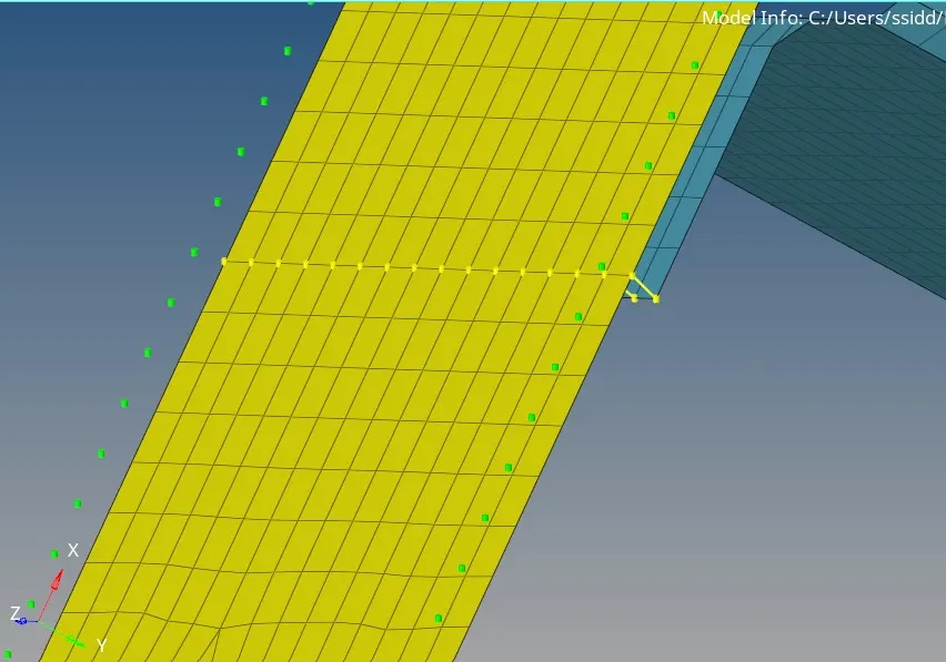
6. Rear_truss_2 & Left_Rail_2:- Bolt Connector
node method used.
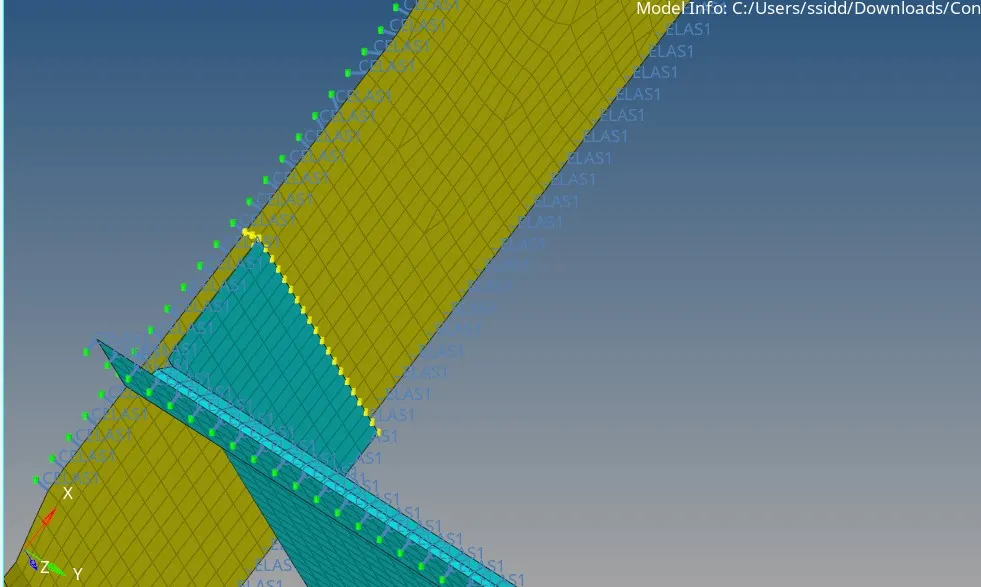 7. Right_Rail_1 & Right_Rail_2:- Spot-weld with Rigid Elements
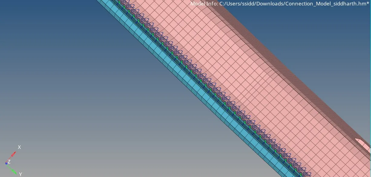
8. Left_Rail_1 & Left_Rail_2:- Spot-weld with Spring Elements
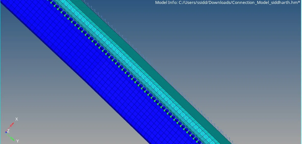
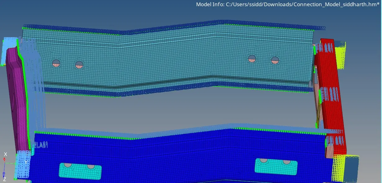
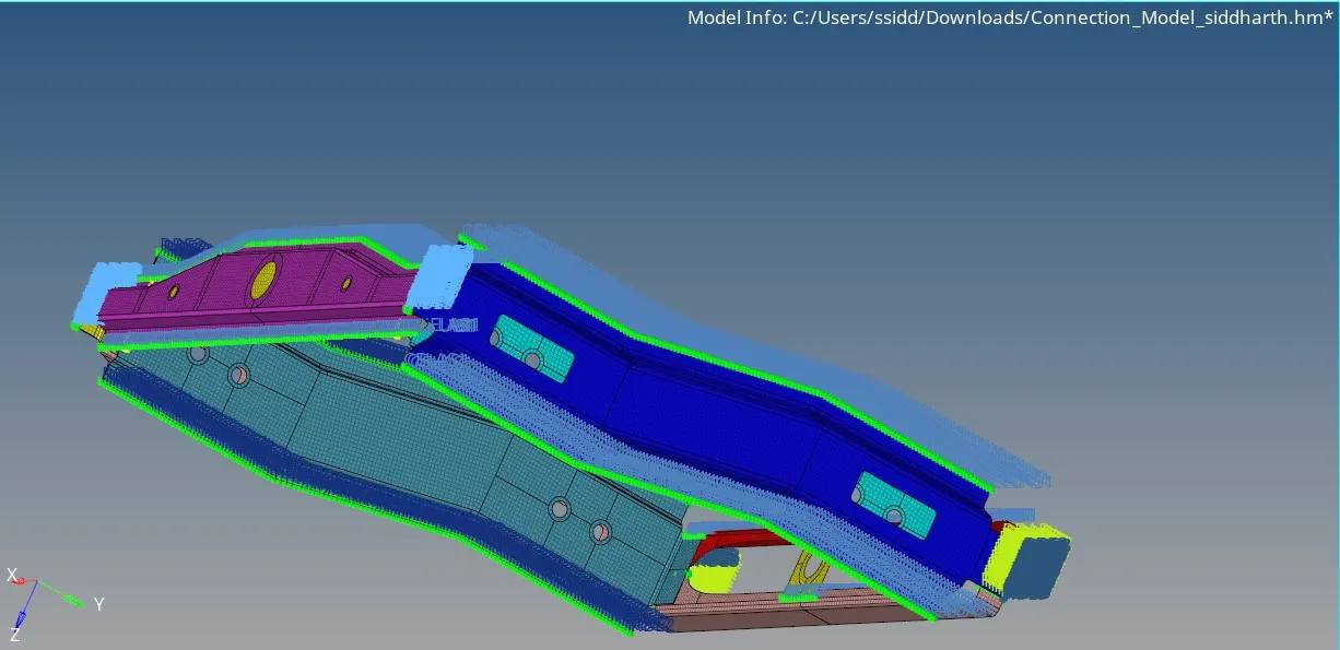
Other components which have not been connected are also connected.
RESULT:
thus we have meshed the geometry and done connections for the given components.