Project 1 - Meshing of Floor Panel
AIM:
For the given Floor Panel model, Check the Geometry cleanup, do the mid surface, and to Mesh it with the below 2D element Quality criteria.
GIVEN DATA:
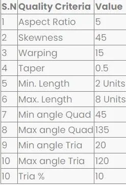
Steps involved in the procedure:
- To check all the geometry error and to fix them.
- Mid surface to be made for all the geometrys.
- To generate mesh with good flow in the given quality criteria.
PROCEDURE:
- Open the Ansa work bench ANSA v22.1.0.
- Import the given hood model from the downloads
- In ANSA we can import all the CAD Software file formats like IGES,STEP,etc.
- And we have to define the material and to orient the components.
- The model consists of the component listed below.
Given model:
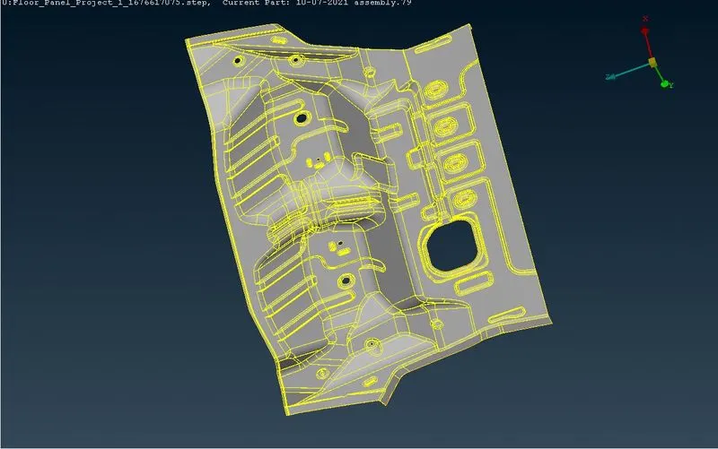
The given cad model consists of 1 component.
STEP 1:
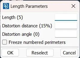
- Before doing the geometry checkup we have give the length for every component to mesh properly.
- Mesh Module >> Perimeters >> Length.
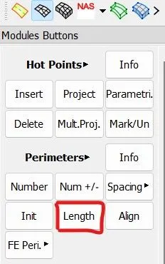
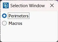
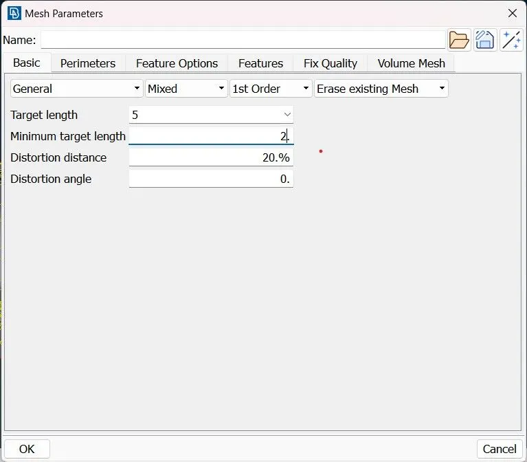
- Then the length of the perimeters and macros should be given 5.
STEP 2:
- We have to fix the geometrical errors in the parent component,Then only we will be able to do midsurface using skin and offset.
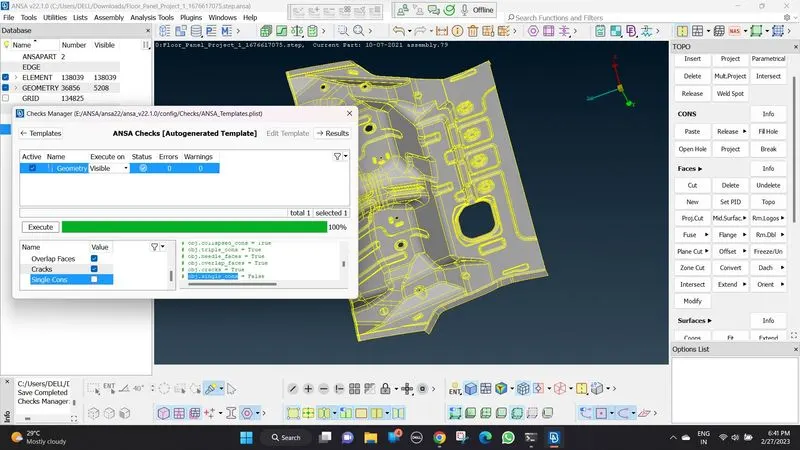
- Tool Bar >> Checks >> Geometry.
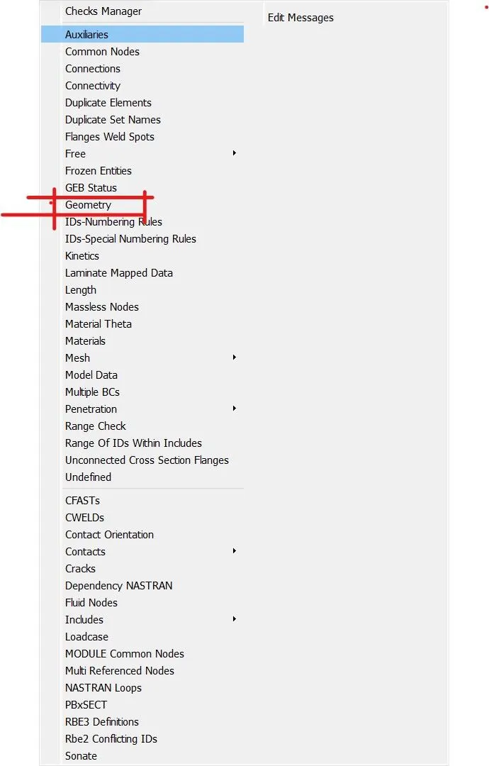
- After clicking on the check geometry and executing it,The geometric errors will be displayed.
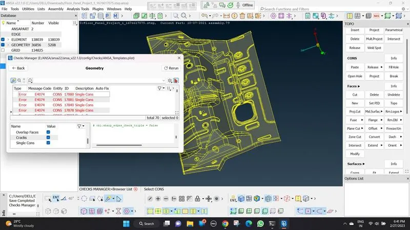
- We can fix that geometric errors by manually or automatically by using the auto fix option.
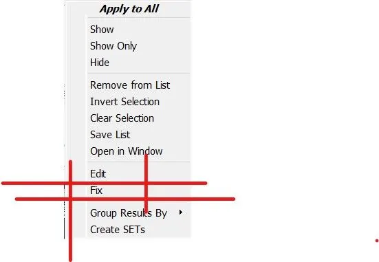
- after fixing the errors, we have to run another check then it will show no errors .
STEP 3:
- Again before doing mid surface we have give the length for every component to mesh properly.Since the length changes after we fix the errors
- Mesh Module >> Perimeters >> Length.
- Then the length of the perimeters and macros should be given 5.
- After giving the length mid sufacing is done
STEP 4:
MID SURFACING:
- mid suface can be done by 2 methods by automatic method and manual method.
- auto method Topo Module >> Faces >> Mid Surface >> Skin >> Select the Face.
- manual method Topo Module >> Faces >> Offset .
- Here we have used offset (manual method) .
- the below image is the mid surface of the component.
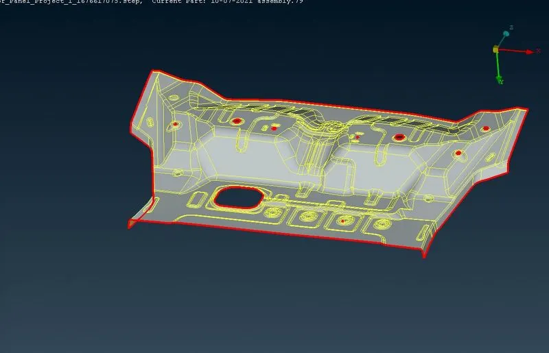
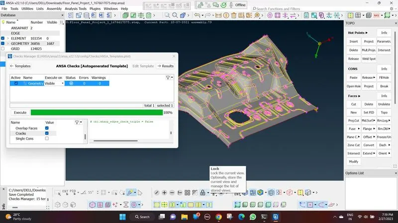
- we run the geometry check up again for the mid surface of the component and we have to fix the errors
STEP 5:
- Before meshing the given data is added to the quality criteria of the components and the target length
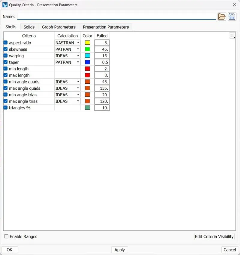
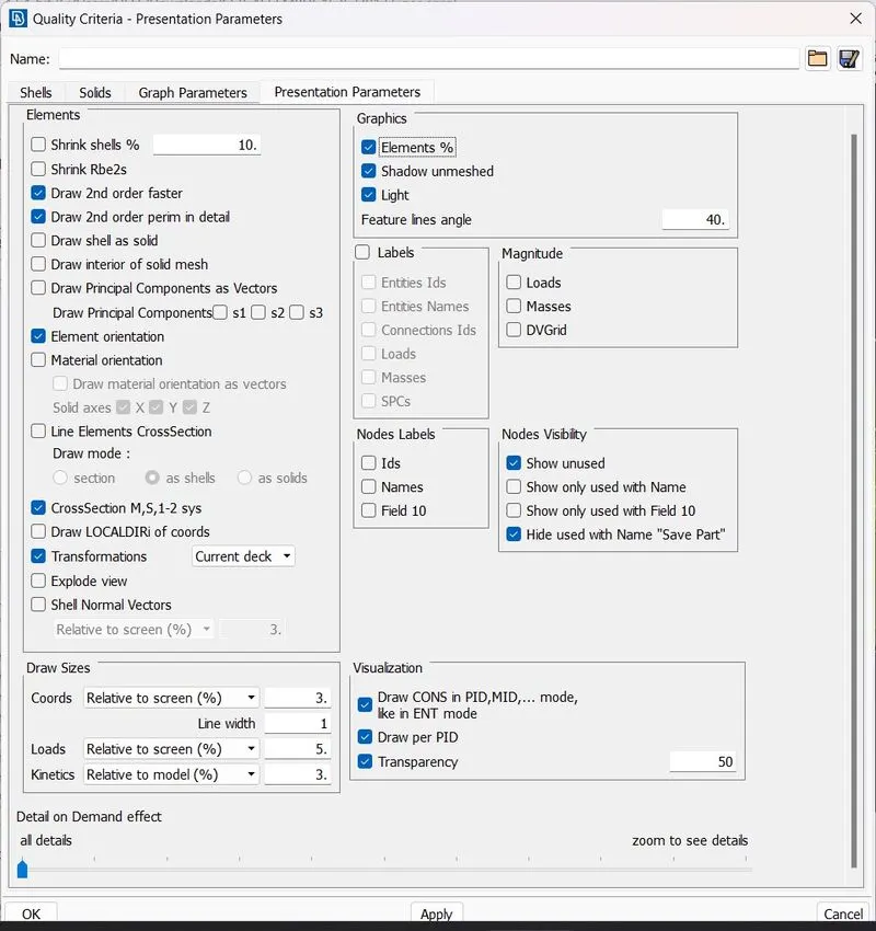
- And in presentation parameters element percentage and all details are turned on for better visibility.
STEP 6:
MESHING:
- To apply mesh use << BEST MESH < MESH GENERATION>> and to remove the mesh use<< ERASE < MESH GENERATION >>.
- To increase the quality of the mesh use <>RECONSTRUCT,<>SMOOTH options.
- To increase the qual;ity manually <> SPLIT /SWAP / JOIN
- the below images are the meshed images of the main component, the component file is shared.
- tria percentage is achieved at 5.11%.
CONCLUSION:
Thus for the given Floor Panel model, the mid surface for the component is generated and the geometrical errors are identified and fixed and meshing for the component with the given element Quality criteria is done.