Week 7-12-Creation of 1D Connectors Challenge
Objective:
Mesh the given model according to given quality parameter
Target Element size - 5 Units
|
S.N |
Quality Criteria |
Value |
|
1 |
Aspect Ratio |
5 |
|
2 |
Skewness |
45 |
|
3 |
Warping |
15 |
|
4 |
Taper |
0.5 |
|
5 |
Min. Length |
2 Units |
|
6 |
Max. Length |
8 Units |
|
7 |
Min angle Quad |
45 |
|
8 |
Max angle Quad |
135 |
|
9 |
Min angle Tria |
30 |
|
10 |
Max angle Tria |
110 |
|
10 |
Tria % |
15 |
also Create a connector and Attach the various parts of the given model
1. Right_Rail_2 & Front_truss_1:- Seam-Quad(angled+capped+L)
2. Left_Rail_2 & Front_truss_1:- Quad elements
3. Front_truss_2, Front_truss_1 & Right_Rail_1:- Spot weld with 2 Layers and 5 mm Diameter
4. Front_truss_2, Front_truss_1 & Left_Rail_1:- Hexa (Adhesive)
5. Rear_truss_2 & Right_Rail_2:- Bolt Connector
6. Rear_truss_2 & Left_Rail_2:- Bolt Connector
7. Right_Rail_1 & Right_Rail_2:- Spot-weld with Rigid Elements
8. Left_Rail_1 & Left_Rail_2:- Spot-weld with Spring Elements
9. Rest all the components left Join them with suitable connectors
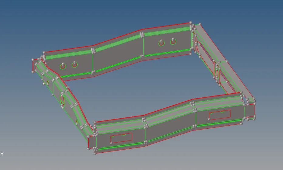
Given Model Image
Procedure:
1. Import the model.
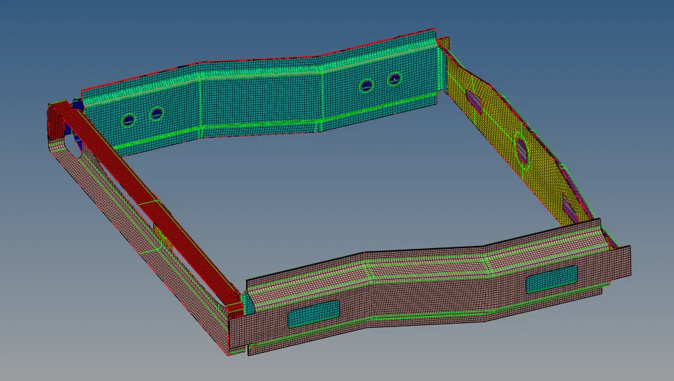
2. Do the Geometry Cleanup and mesh the given component.
3. Create material - 'steel'. For this
right click on left panner >> select material >> material name - 'steel' >> Card Image - 'MAT1' >> E = 210000 >> G = 80769 >> NU = 0.3
4. Create Property . For This
right click on left pannel >> select property >> property name _ "Property1" >> Card Image - "PSHELL" >> Material = "Steel" >> Thiskness - 1 mm
5. Now Assign property to component. For this
Select all components >> right click >> assign >> select property1 >> apply and OK.
Connections
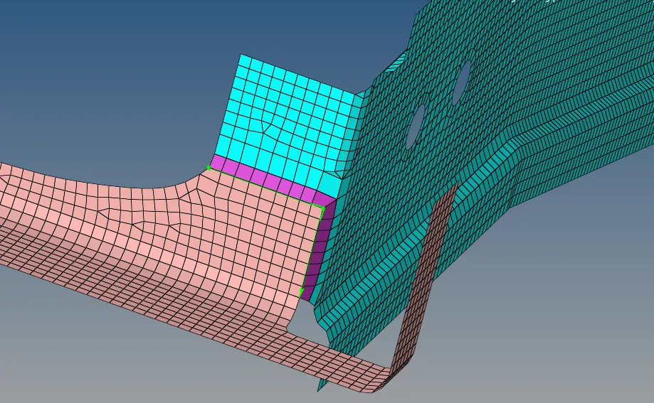
1. Right_Rail_2 & Front_truss_1:- Seam-Quad(angled+capped+L)
Go to 3D >> Connectors >> seam >> Select nodes >> give spacing = 5 mm (about target length of meshing) >> tolerance = 10 >> type = Seam-Quad(angled+capped+L) >> select both components >> create and return.
2. Left_Rail_2 & Front_truss_1:- Quad elements
Go to 3D >> Connectors >> seam >> Select nodes >> give spacing = 5 mm (about target length of meshing) >> tolerance = 10 >> type = Quad >> select both components >> create and return.
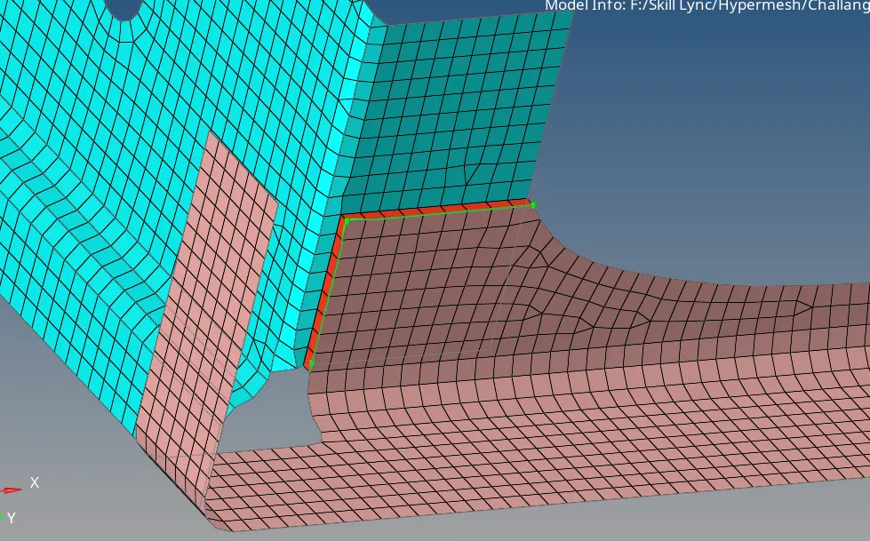
3. Front_truss_2, Front_truss_1 & Right_Rail_1:- Spot weld with 2 Layers and 5 mm Diameter
Go to 3D >> Connectors >> spot >> Select node >> select 2 component >> tolerance = 10 >> type = acm General >> diameter = 5mm s>> create and return.
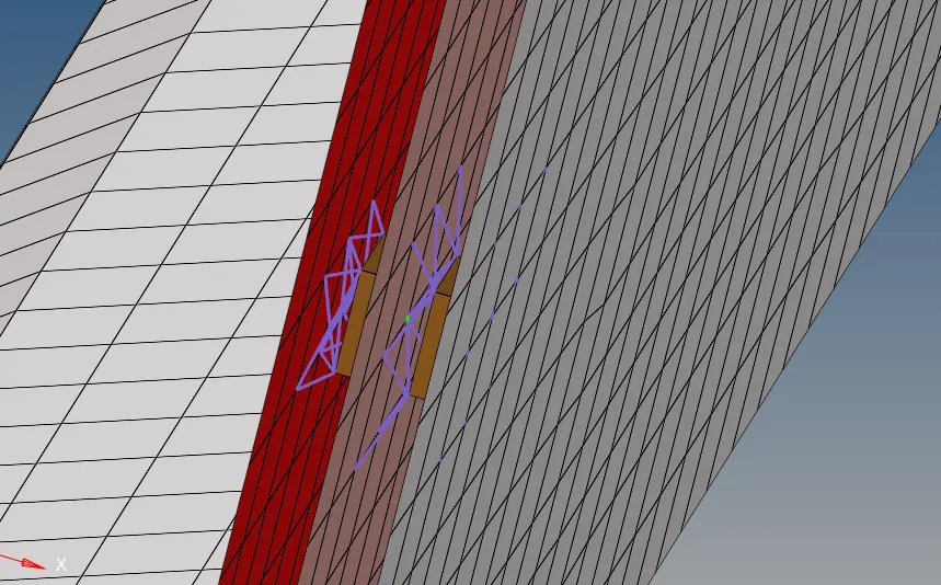
4. Front_truss_2, Front_truss_1 & Left_Rail_1:- Hexa (Adhesive)
Go to 3D >> Connectors >> area >> Select elements >> select 2 component >> tolerance = 10 >> type = adhesive >> create and return.
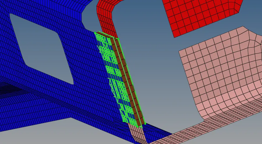
5. Rear_truss_2 & Right_Rail_2:- Bolt Connector
Go to 3D >> Connectors >> bolt >> Select nodes >> select component >> tolerance = 30 >> type = bolt (general) >> select create hole, if any >> create and return.
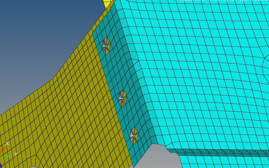
6. Rear_truss_2 & Left_Rail_2:- Bolt Connector
Similarly previous steps
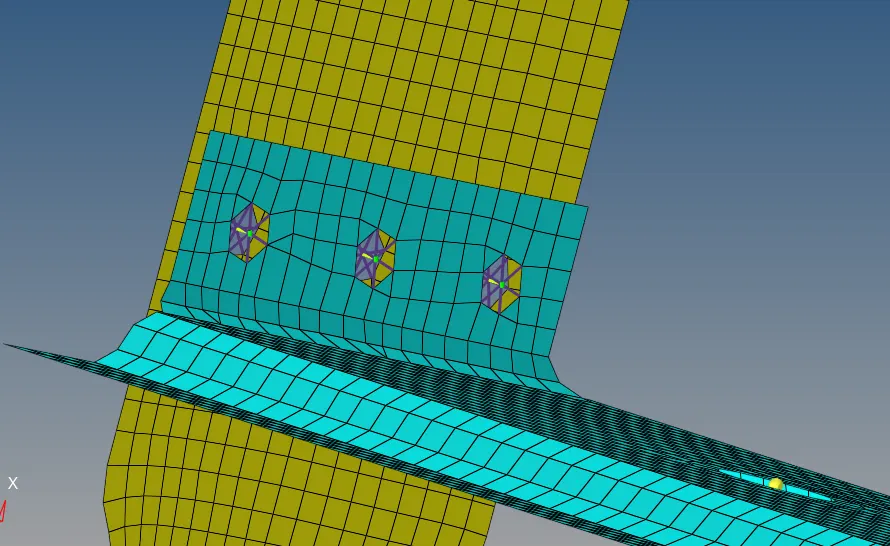
7. Right_Rail_1 & Right_Rail_2:- Spot-weld with Rigid Elements
Go to 3D >> Connectors >> spot >> Select nodes >> select component >> tolerance = 10 >> type = rigid >> create and return.

8. Left_Rail_1 & Left_Rail_2:- Spot-weld with Spring Elements
Go to 3D >> Connectors >> spot >> Select nodes >> select component >> tolerance = 10 >> type = spring >> create and return.
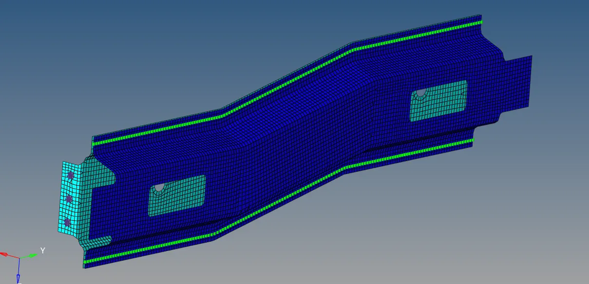
Conclusion
Thus we have completed the meshing and connection work.
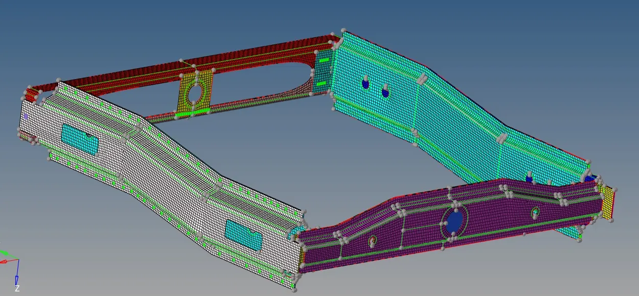
Final Model Image