Week-6 : Turbocharger Modelling
What is meant by Turbocharger??
- A turbocharger, (or turbo), is a turbine-driven forced induction device that increases an internal combustion engine’s efficiency and power output by forcing extra air into the combustion chamber.
- This improvement over a naturally aspirated engine’s power output is due to the fact that the compressor can force more air—and proportionately more fuel—into the combustion chamber than atmospheric pressure alone.
- In naturally aspirated piston engines, intake gases are “pushed” into the engine by atmospheric pressure filling the volumetric void caused by the downward stroke of the piston (which creates a low-pressure area), similar to how liquid is drawn up into a syringe.
- The objective of a turbocharger is to improve an engine’s efficiency by increasing the density of the intake gas (usually air), thereby allowing more power per engine cycle.
- The turbocharger’s compressor draws in ambient air and compresses it before it enters the intake manifold at increased pressure. This results in a greater mass of air entering the cylinders on each intake stroke. The power needed to spin the centrifugal compressor is derived from the kinetic energy of the engine’s exhaust gases.
- A turbocharger may also be used to increase fuel efficiency without increasing power. This is achieved by recovering waste energy in the exhaust and feeding it back into the engine intake. By using this otherwise wasted energy to increase the mass of air, it becomes easier to ensure that all fuel is burned before being vented at the start of the exhaust stage.
Types of Turbochargers
- Single-Turbo.
- Twin-Turbo.
- Twin-Scroll Turbo.
- Variable Geometry Turbo.
- Variable Twin Scroll Turbo.
- Electric Turbo.
Single Turbo: single turbo is the Cost effective way of increasing an engine’s power and efficiency, and as such have become increasingly popular, allowing smaller engines to increase efficiency by producing the same power as larger naturally-aspirated engines, but with a lower weight.Single turbochargers are what most people think of as turbos. By differing the size of the elements within the turbo, completely different torque characteristics can be achieved. Large turbos provide higher levels of top end power, whilst smaller turbos can spool faster and provide better low-end power. They do however tend to work best within a narrow RPM range, and drivers will often experience ‘turbo-lag’ until the turbo starts to operate within its peak rev band. Single turbos tend to have a fairly narrow effective RPM range. This makes sizing an issue, as we have to choose between good low-end torque or better high-end power.
Twin Turbo:Twin-turbos mean adding a second turbocharger to an engine. In the case of V6 or V8 engines, this can be done by assigning a single turbo to work with each cylinder bank. Alternatively, one smaller turbo could be used at low RPMs with a larger turbo for higher RPMs. This second configuration (known as twin sequential turbocharging) allows for a wider operating RPM range, and provides better torque at low revs (reducing turbo lag), but also gives power at high RPMs. But, having two turbos, significantly increases the complexity and associated costs. For parallel twin turbos on ‘V’ shaped engines, the benefits (and drawbacks) are very similar to single turbo setups.
Twin-Scroll Turbo:Twin-scroll turbochargers require a divided-inlet turbine housing and exhaust manifold that pairs the correct engine cylinders with each scroll independently. By using two scrolls, the exhaust pulses are divided. For example, in a four-cylinder engine (with a firing order 1-3-4-2), cylinders 1 and 4 might feed to one scroll of the turbo, while cylinders 2 and 3 feed to a separate scroll. This layout provides more efficient delivery of exhaust gas energy to the turbo, and results and helps provide denser, purer air into each cylinder. More energy is sent to the exhaust turbine, meaning more power. Again, there is a cost penalty for addressing the complexity of a system requiring complicated turbine housings, exhaust manifolds and turbos. More valve overlap is possible without hampering exhaust scavenging, meaning more tuning flexibility. It requires a specific engine layout and exhaust design.
Variable Geometry Turbo:
VGTs include a ring of aerodynamically-shaped vanes in the turbine housing at the turbine inlet. In turbos for passenger cars and light commercial vehicles, these vanes rotate to vary the gas swirl angle and the cross-sectional area. These internal vanes alter the turbos area-to-radius (A/R) ratio to match the engines RPM, and so give peak performance. At low RPM, a low A/R ratio allows the turbo to quickly spool up by increasing exhaust gas velocity and. At higher revs the A/R ratio increases, therefor by allowing increased airflow. This results in a low boost threshold reducing turbo lag, and provides a wide and smooth torque band. It has Wide, flat torque curve. Effective turbocharging at a very wide RPM range. It Requires just a single turbo, simplifying a sequential turbo setup into something more compact. It is Typically only used in diesel applications where exhaust gases are lower so the vanes will not be damaged by heat.
Variable Twin Scroll Turbo:VTS turbocharger combines the advantages of a twin-scroll turbo and a variable geometry turbo. It does this by the use of a valve which can redirect the exhaust airflow to just a single scroll, or by varying the amount the valve opens can allow for the exhaust gases to split to both scrolls. The VTS turbocharger design provides a cheaper and more robust alternative to VGT turbos, meaning it is a viable option for petrol engine applications. It Allows for a wide, flat torque curve. It is More robust in design versus a VGT, depending on the material selection.
Electric Turbo:An electric turbocharger is used to eliminate turbo lag and assist a normal turbocharger at lower engine speeds where a conventional turbo is not most efficient. This is achieved by adding an electric motor that spins up the turbo’s compressor from start and through the lower revs, until the power from the exhaust volume is high enough to work the turbocharger. This approach makes turbo lag a thing of the past, and significantly increases the RPM band within which the turbo will efficiently operate. So far, so good. It appears that electronic turbos are the answer to all the negative characteristics of conventional turbochargers, however there are some disadvantages. Most are around cost and complexity, as the electric motor must be accommodated and powered, plus also cooled to prevent reliability issues.
Explore tutorial number 6 and 7
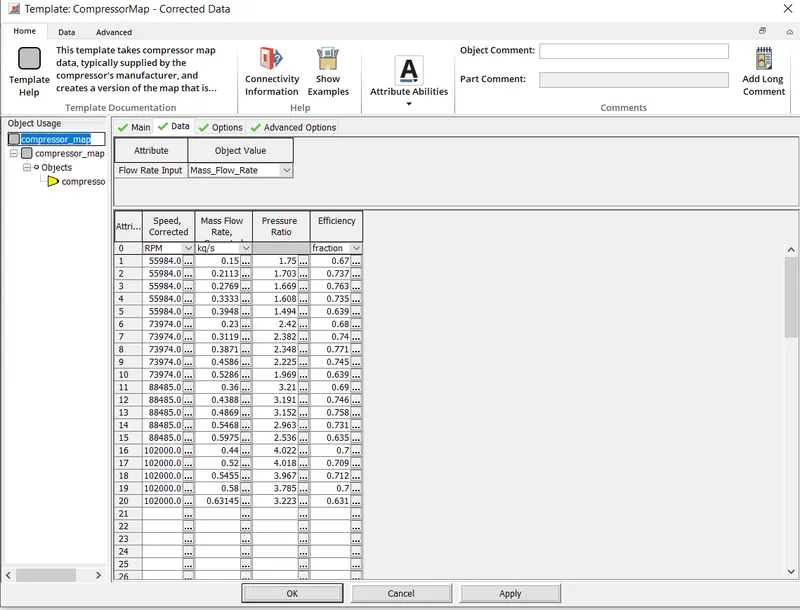
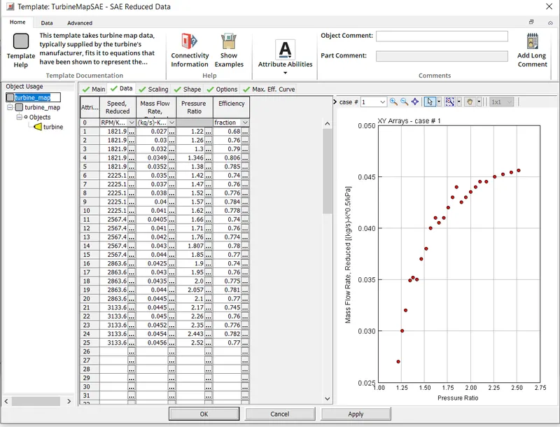
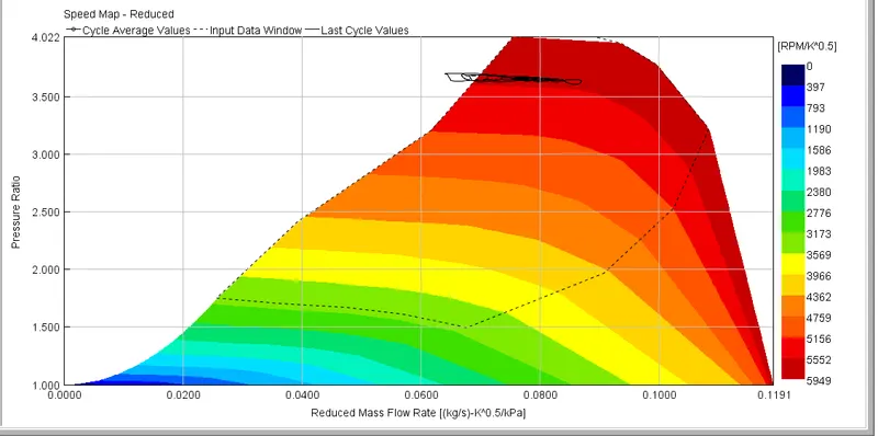
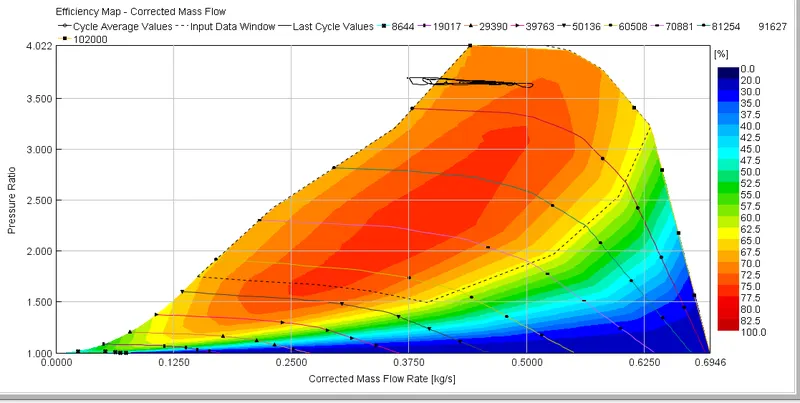
- In this model again we have 6 cylinders diesel engine with two inlets to the turbocharger which is a collection of 6 cylinders splitting into 2 inlets. This model is conceptually the same as the above model in tutorial no. 6 with the actual turbocharger setup implemented here, where the turbine is connected with the compressor impeller with the rotating shaft as seen in the image below. Here for the turbine and compressor inputs, we have a turbine map and compressor map which is a contour plot of Pressure ratio v/s Mass flow rate. This turbine and compressor map data consists of parameters like Rotational speed, Mass flow rate, Pressure Ratio, and efficiency.
- In the below image, we can see the 6 Dual twin Turbocharger Cylinder engine
tutorial 6
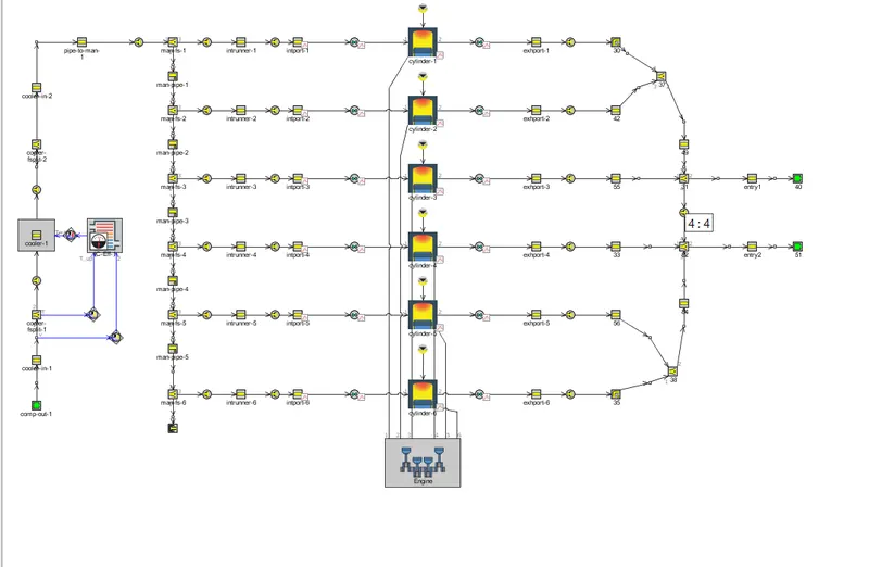
tutorial7
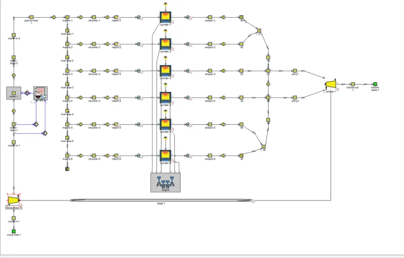
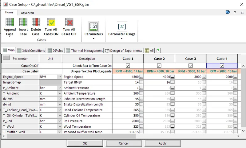
case set up :-
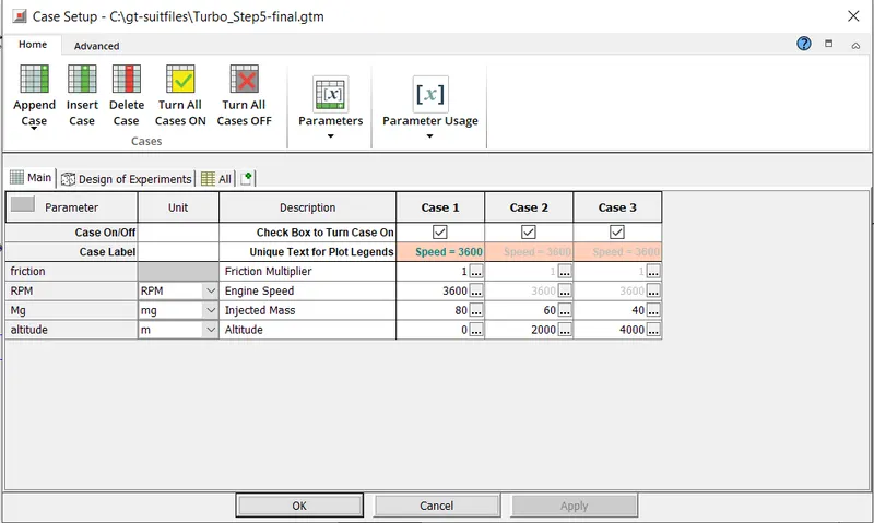
compressor map data
turbocharger map data
compressor plot for case 1
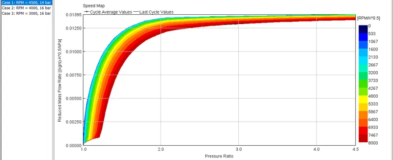
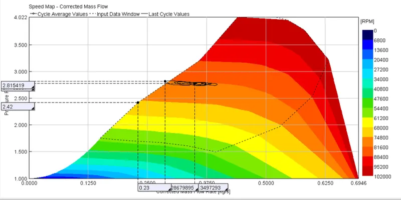
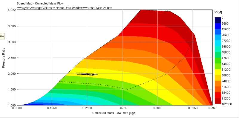
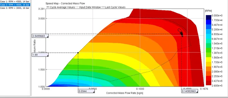
speedmap
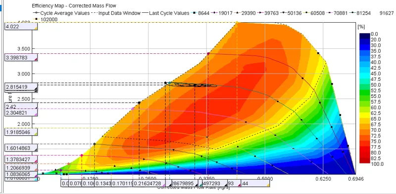
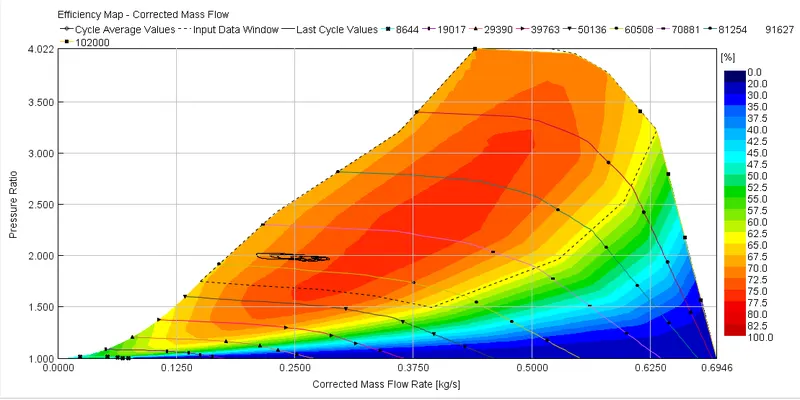
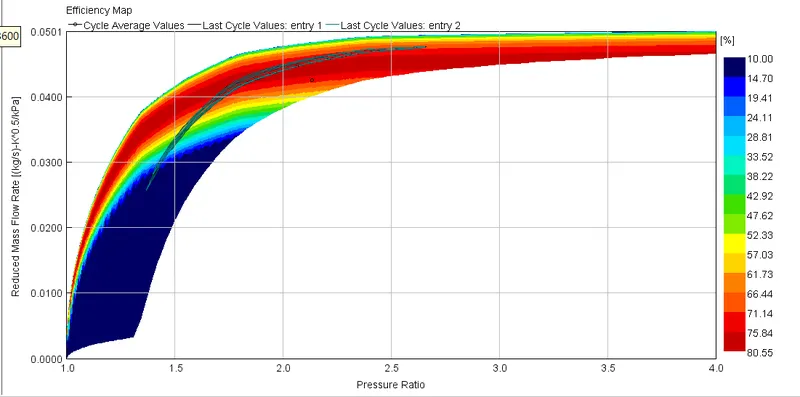
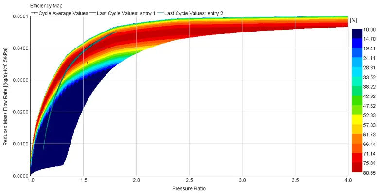
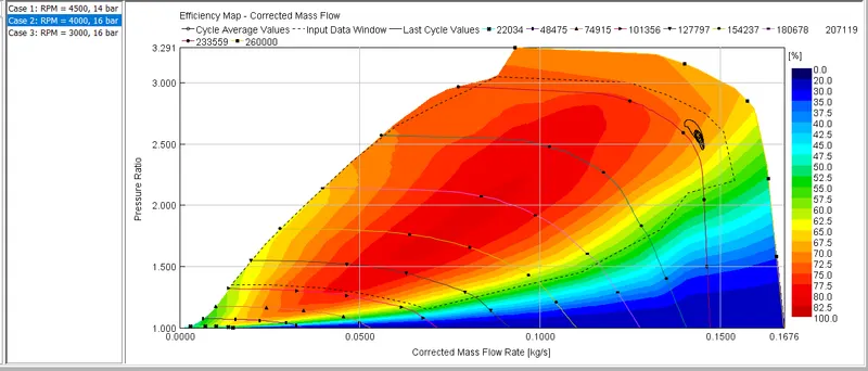
efficency map
case 2
case 3
turbo maping
speed map for case 1,2 and 3
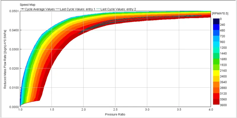
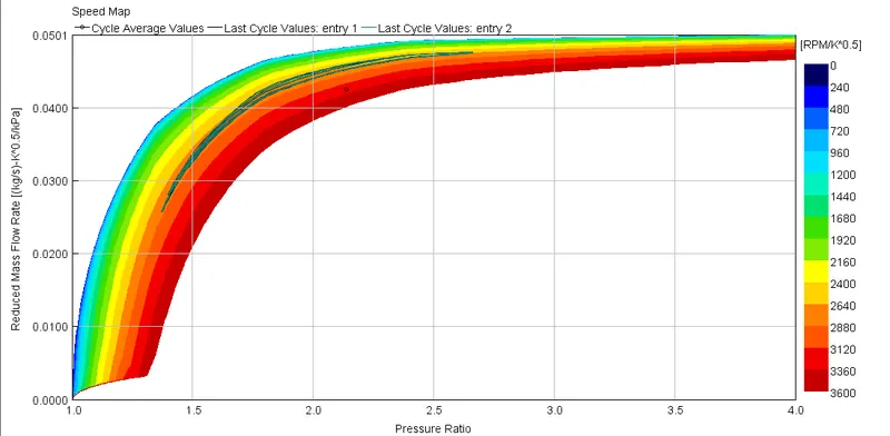
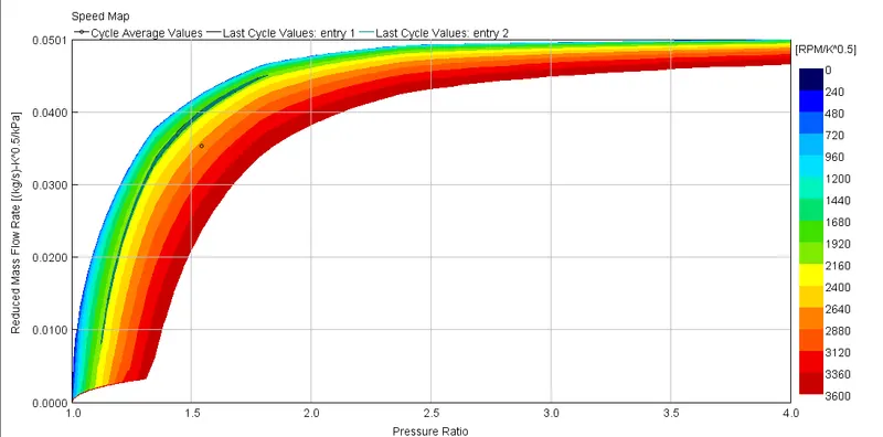
efficency map for 1,2 and 3
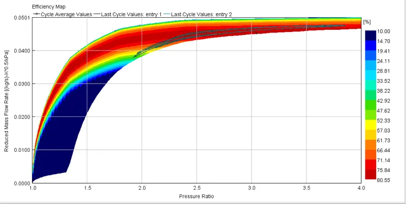
In which application Variable Geometry Turbine is beneficial?
- VGTs tend to be much more common on diesel engines, as lower exhaust temperatures mean they are less prone to failure. Early gasoline-engine VGTs required significant pre-charge Cooling to extend the turbocharger life to reasonable levels, but advances in technology have improved their resistance to high-temperature gasoline exhaust, and they have started to appear increasingly in gasoline-engined cars
- Typically, VGTs are only found in OEM applications due to the level of coordination required to keep the vanes in the most optimal position for whatever state the engine is in. However, there are aftermarket VGT control units available, and some high-end aftermarket engine management systems can control VGTs as well.
- VGT devices are designed to increase boost pressure at low speeds, reduce response times, increase available torque, decrease the boost at high engine speeds to prevent over-boosting, reduce engine emissions, improve fuel economy and increase the overall turbocharger operating range
- This design is mostly limited to small engines and light-duty applications (passenger cars, race cars, and light commercial vehicles).
Diesel VGT EGR:
- The variable geometry turbine allows significant flexibility over the pressure ratio across the turbine. In diesel engines, this flexibility can be used for improving low-speed torque characteristics, reducing turbocharger lag, and driving EGR flow.
- Variable geometry turbocharger is designed to: increase intake air boost pressure at low engine speeds. improve the response time of the turbocharger during transient engine operation phases. increase the availability of the maximum engine torque.
- Engine downsizing through turbocharging is a proven method of improving fuel economy by using a smaller engine operating at higher levels of specific engine load and higher efficiency. Turbocharging is more challenging for the gasoline engine than the diesel engine due to the higher variability in the flow rate of air and the higher exhaust gas temperature. Although the variable geometry turbine offers the potential for improving the low-end torque, lowering part-load fuel consumption, and delivering a fast transient response on a downsized gasoline engine, the cost, durability and the limited allowable turbine inlet temperature on the currently available devices present challenges to widespread application
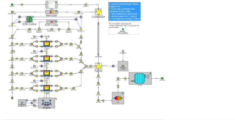
- The Diesel VGT EGR model is shown below:
Explore example- Diesel VGT EGR and understand the modeling part
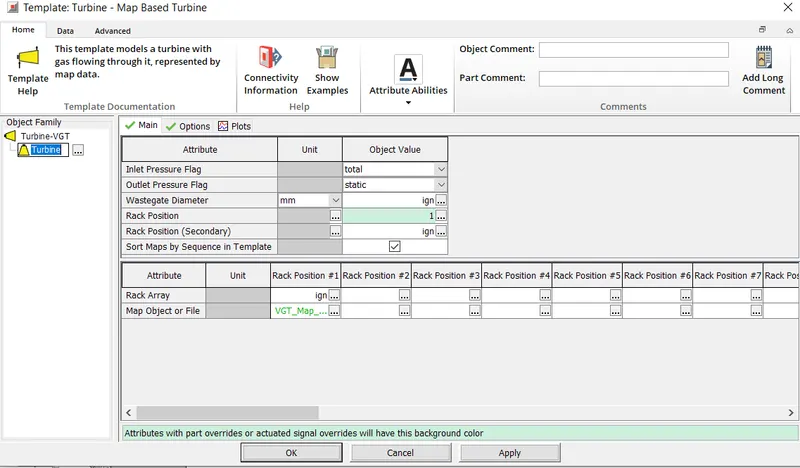
case set up
compressor plot
speed map plot
efficency plot
turbo map
speed map