Week-6 : Turbocharger Modelling
AIM: Modelling of Turbocharger in GT-Power.
OBJECTIVE:
- List down different TC and locate examples from GT Power
- Explore tutorial number 6 and 7
- Plot operating points on compressor and turbine maps
- In which application Variable Geometry Turbine is beneficial?
- Explore example- Diesel VGT EGR and understand the modeling part
OBJECTIVE:1 (List down different TC and locate examples from GT Power)
There are three types of Turbochargers that are used for practical purposes
They are:
- Fixed geometry Turbocharger
- Wastegate turbocharger
- Variable Geometry Turbocharger or VGT
- Fixed geometry Turbocharger
- This is the simplest form of turbocharger whose geometry is fixed. We cannot control the geometry and speed of the turbine or compressor of this turbocharger which makes it prone to mechanical failure at a very higher speed.
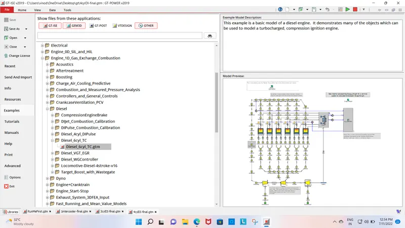
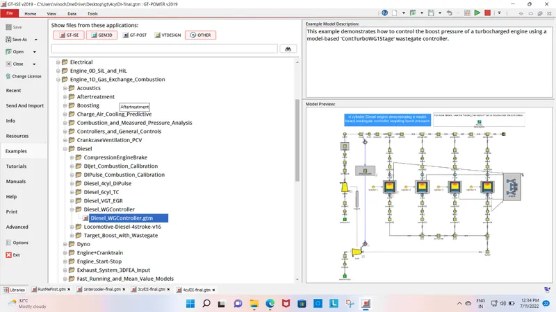
2 Wastegate turbocharger
- The wastage is the amount of exhaust gas which is going turbine is controlled by a small opening is known as wastage.
- Due to this mechanism, the speed of the turbine can be controlled and hence can be prevented from mechanical failure.
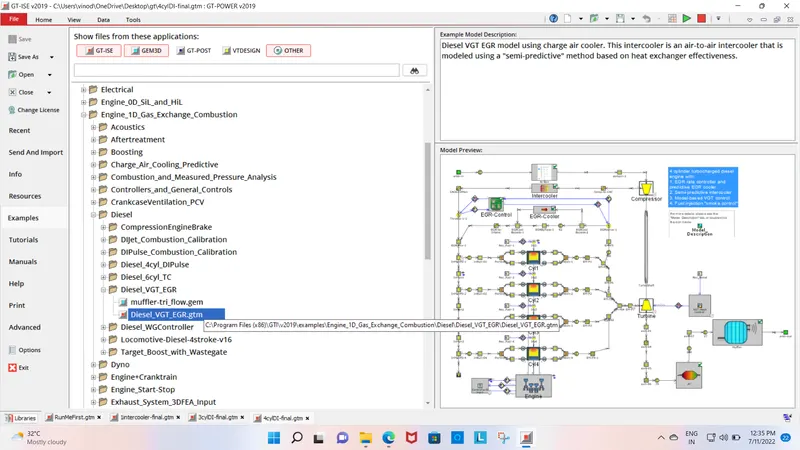
3. Variable Geometry Turbocharger or VGT
- there are vanes around the turbine entry which control the number of exhaust gases entering the turbine inlet. So in that way, we can control the rpm of the turbine and hence the compressor.This is the most advanced version of the turbocharger and hence the most costly.
OBJECTIVE(2)-Explore tutorial number 6 and 7
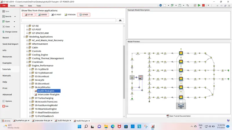
Tutorial(6):
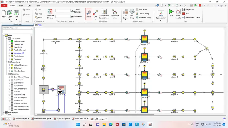
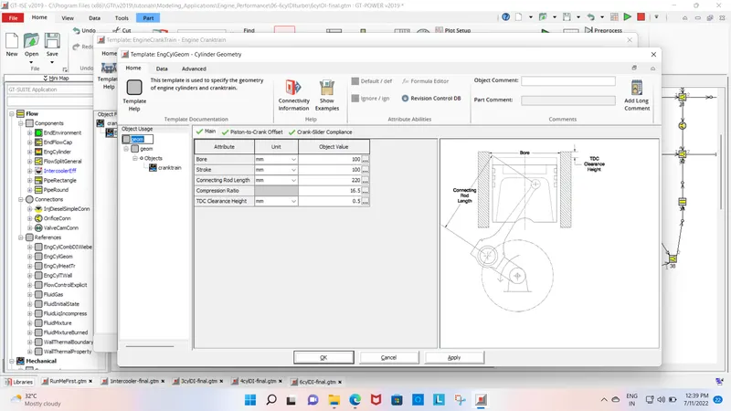
CYLINDER GEOMETRY
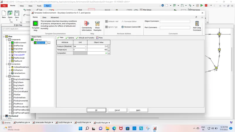
INLET VALVE
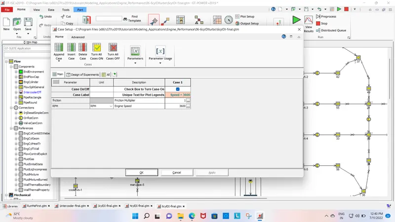
CASE SETUP
RESULTS:
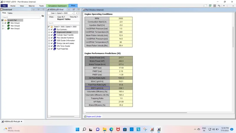
we see at 3600 rpm of engine speed at this speed we obtain brake power and brake torque are 217.7 Kw and 577.6 N-m and air flow rate is 1096.3Kg/h with the Airflow ratio is 21.09
Tutorial (7)
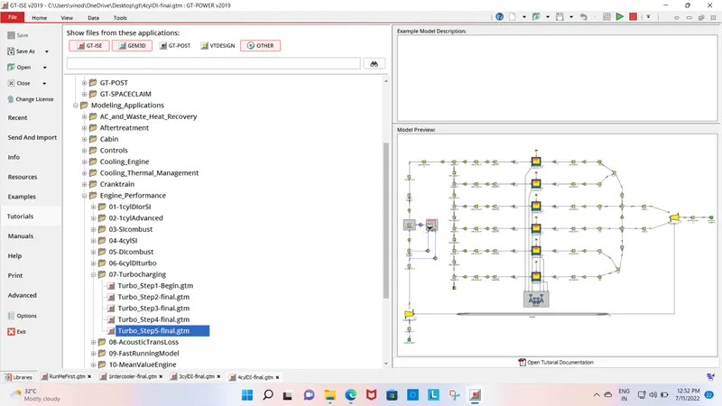
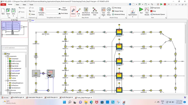
CYLINDER GEOMETRY:
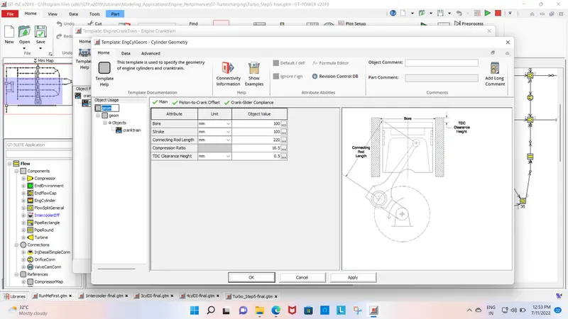
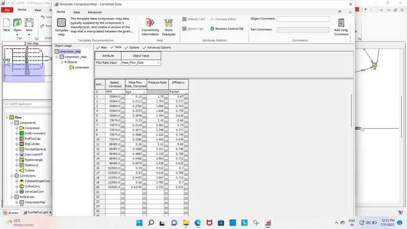
COMPRESSOR MAP DATA:
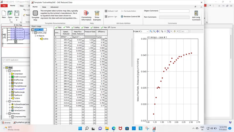
TURBINE MAP
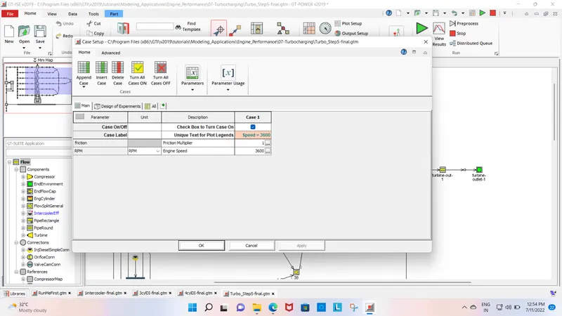
CASE SETUP
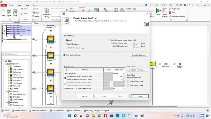
RUN THE SETUP
RESULTS:
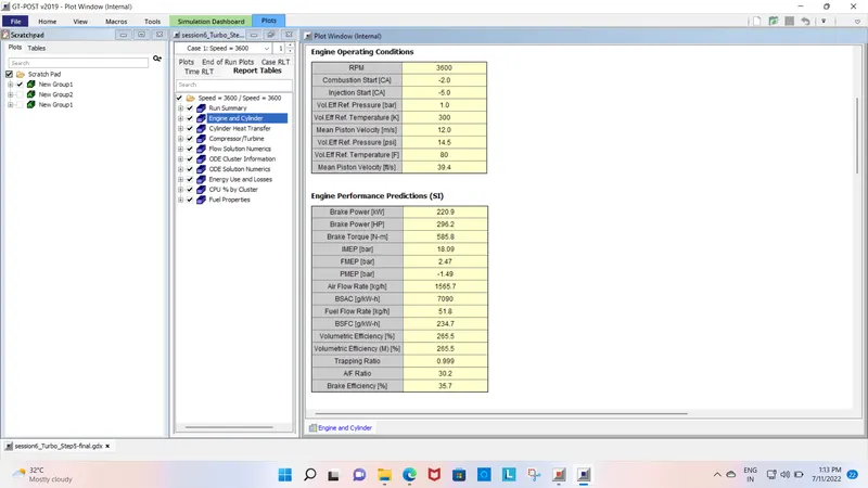
COMPARE BOTH TUTORIALS 6 AND 7.
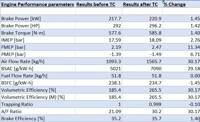
As we see the difference b/w the use of turbocharger and without turbocharger. We conclude that the overall engine performance is increased by using a turbo charger.
the
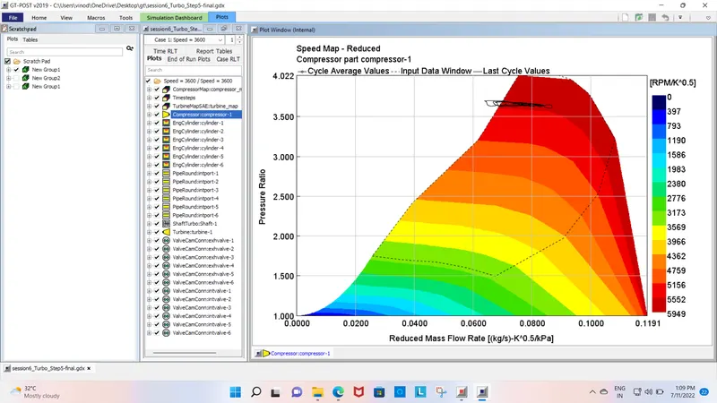
3. Plot operating points on compressor and turbine maps:
COMPRESSOR
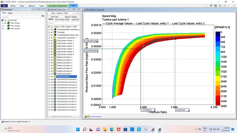
TURBINE:
4. In which application Variable Geometry Turbine is beneficial?
- VGT devices are designed to increase boost pressure at low speeds, reduce response times, increase available torque, decrease the boost at high engine speeds to prevent over-boosting, reduce engine emissions, improve fuel economy and increase the overall turbocharger operating range.
5. Explore example- Diesel VGT EGR and understand the modeling part
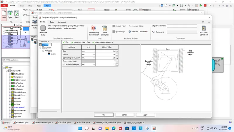
cylinder geometry:
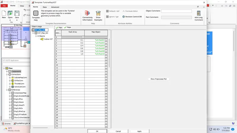
TURBINE MAP:
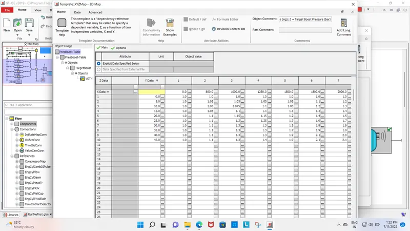
compressor map
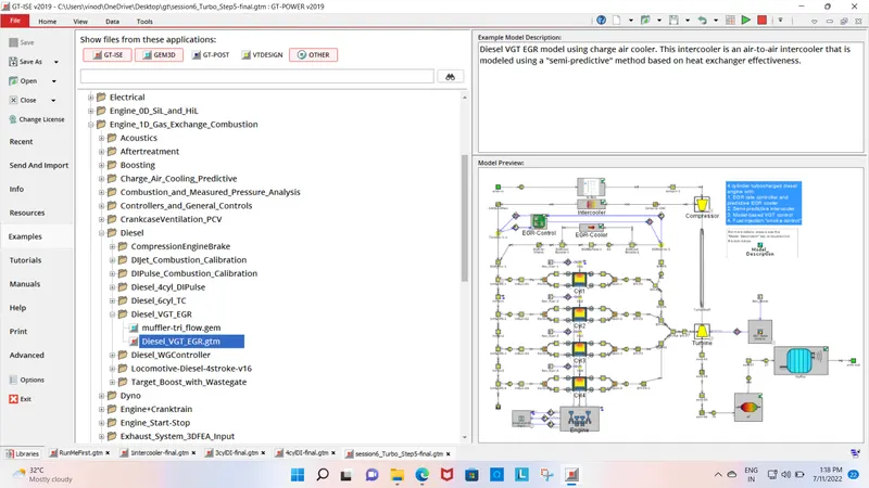
In this model, we can see that the exhaust exit is divided into 3 parts. One part of the exhaust gas goes through the EGR system, one part goes through the after-treatment system and the last part of the exhaust gas goes through the VGT turbocharger system.
The turbine part of the turbocharger is controlled by the VGT rack control module which controls the position of the guide vanes of the turbo housing.
The rec boost template is connected to the vgt rack control. It receives the signals from the ECU wirelessly to tell the VGT rack controller about the boost pressure at a particular RPM. If the boost pressure is going high which needs to be lower the VGT rack controller changes the position of the guide vanes that permits only the required amount of exhaust gases so that the mechanical failure of the turbo can be prevented.
This technology helps to reduce the turbo lag and allows the engine to perform better at every operating range