Week-6 : Turbocharger Modelling
- Different types of Turbocharger are as follow
- Fixed Geometry Turbocharger
- Wastegate Turbocharger
- Twin Scroll Turbocharger
- Two Level Turbocharger
- Variable Geometry Turbocharger
- E-turbo
- Fixed Geometry Turbocharger
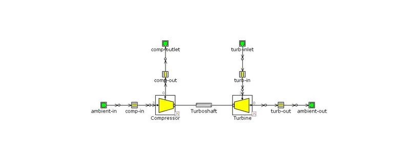
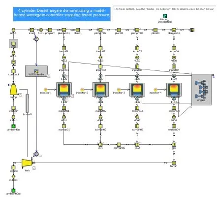
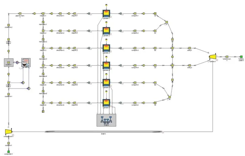
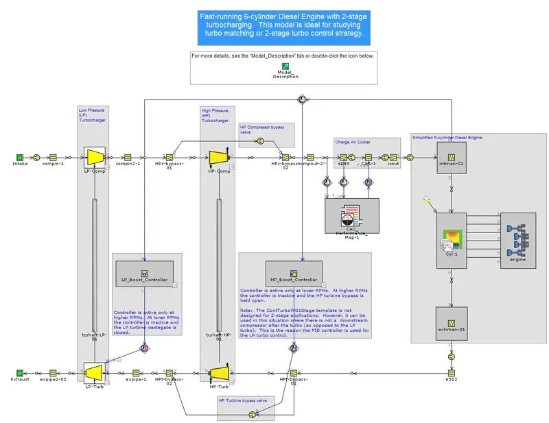
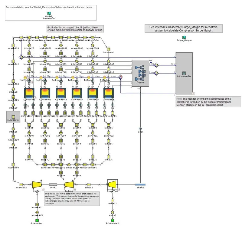
- Tutorials 6 & 7
- Tutorial 6 is about intercooler modeling and EndEnvironments of Turbocharger conditions. Instead of modeling the entire turbocharger, we can directly use turbocharger pressure & temperature as intake conditions when only those are our requirements or we already have static data of both parameters.
- Tutorial 7 is about modeling a turbocharging system. Like actual engine system it start from ambient condition. For actual mapping of compressor and turbocharger, Speed, PR ratio, Mass Flow rate & efficiency data are required which should be at least 4 points for each given speed. Given Tutorial is only about fixed geometry tubocharger but variable geometry turbocharger can also be created using multiple maps & different rack positions. Both compressor and turbine are connected by shaft which also needs to be model using initial speed & moment of inertia.
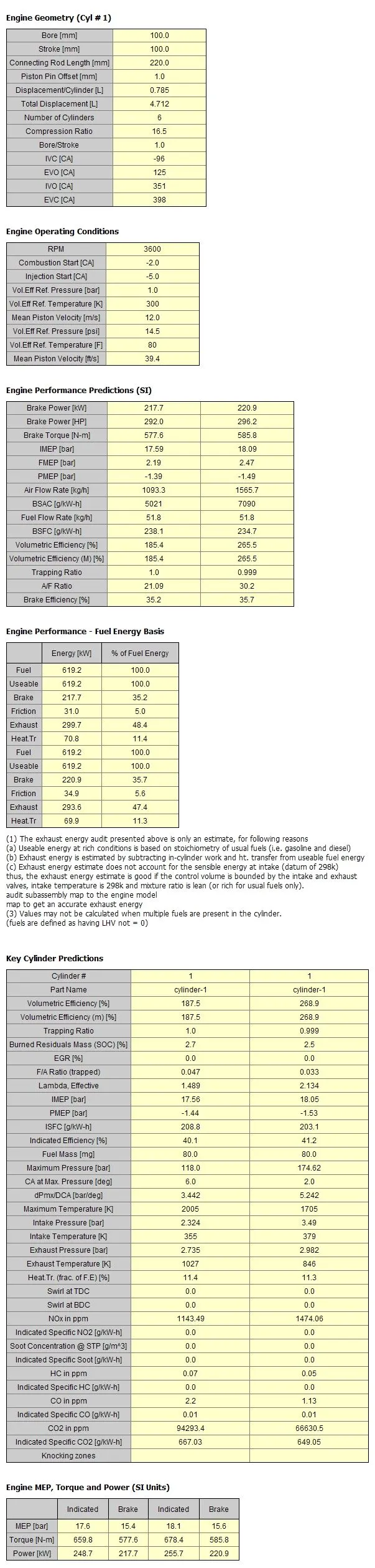
- The below table shows a comparison of performance for Tutorial 6 (Left)& 7 (Right) models.
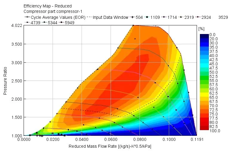
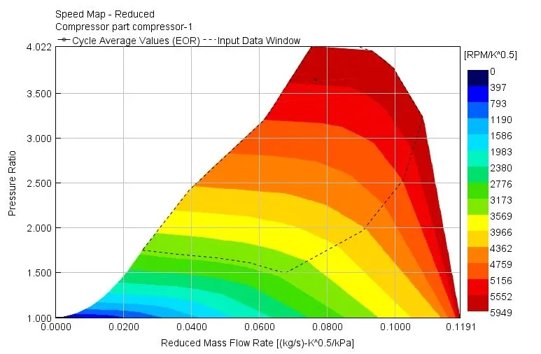
- Compressor & Turbine Operating points
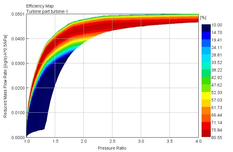
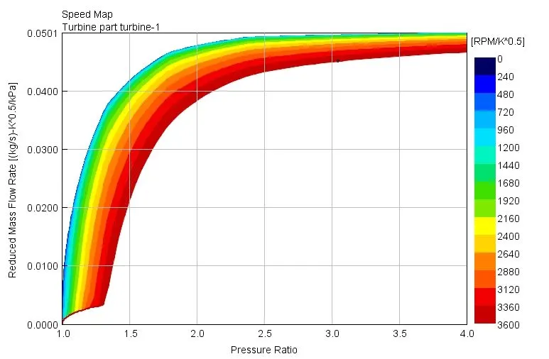
- Note - tiny black ring or circle in all graph is operating point of that part
- Compressor Efficiency Map - Operating point
- Compressor Speed Map - Operating point
- Turbocharger Efficiency Map - Operating point
- Turbocharger Speed Map - Operating point
- Variable Geometry Turbocharger
- Turbocharger's main purpose is to increase torque by boost pressure. Variable Geometry Turbochargers are beneficial where an instantaneous boost in pressure is required at low engine speed and turbo lag works as an important factor in boost. Also, Fuel economy is not considered for engine efficiency, Only engine power is the main goal. For example - F1 Cars
- Diesel VGT EGR
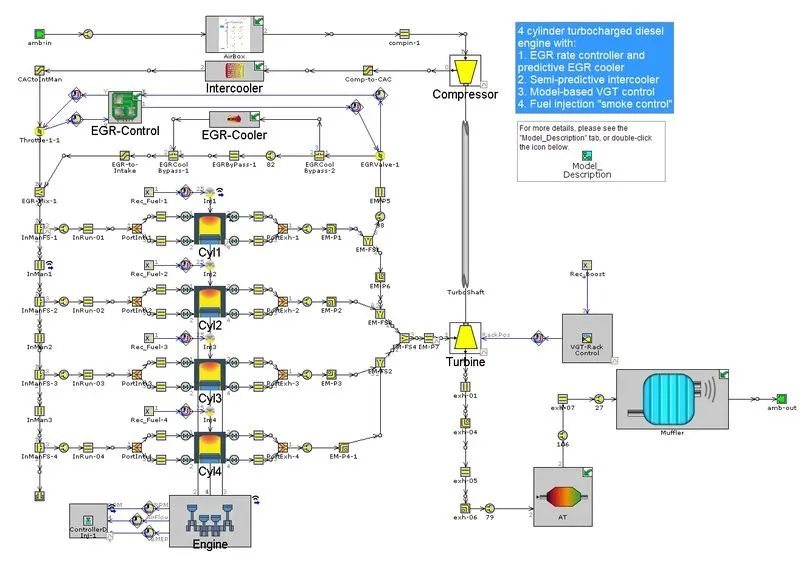
The entire model is a combination of application-based engine systems. it has Air filtration, EGR, Intercooling, Turbocharging, After-Treatment systems. Entire system flow is something like this, From atmosphere > AirBox (Air Filteration) > Compressor > Intercooler > Air + EGR mixing > Intake manifold > Cylinder > Exhaust manifold > EGR + Exhaust > Turbine > Aftertreatment > Muffler > Atmosphere. AirBox was created using round pipes, FlowSplit controls, and orifices which is important since it controls the flow. After AirBox, Intercooler is modeled using an intercooler template & general flow controls to reduce the temperature of pressurized airflow coming from the compressor. Next is the EGR system, which is made of two parts first is flow control and the second is cooling. EGR cooler reduces the temperature of exhaust which is being circulated while Control system is for flow control. By measuring the air mass flow rate coming from the intercooler, it opens/closes the EGR valve. Given EGR system is moderated which automatically controls from using data from the sensor, previously it was controlled manually.
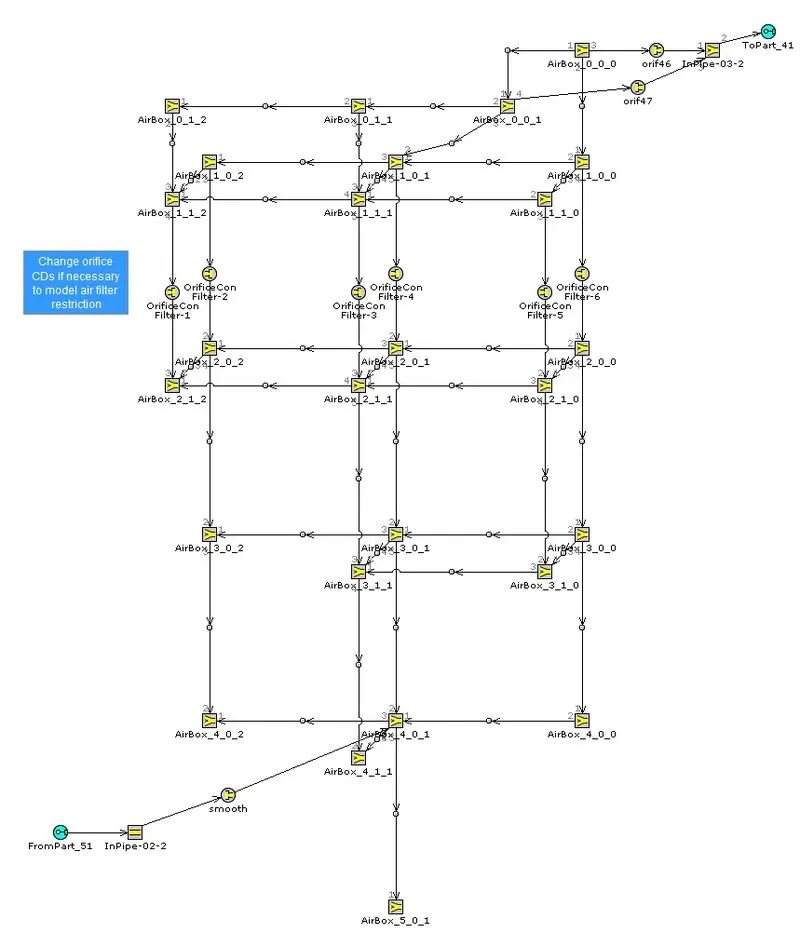
Figure - Airbox
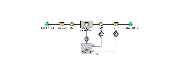
Figure - Intercooler
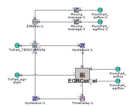
Figure - EGR controller
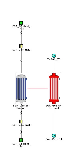
Figure - EGR Cooler
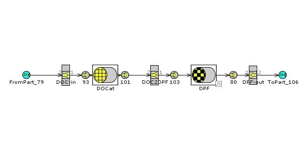
Figure - AfterTreatment
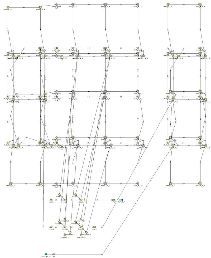
Figure - Muffler