Week- 6 - Solid meshing
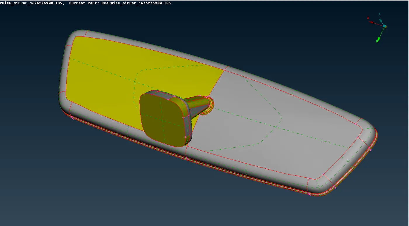
Aim: To 3D Mesh the REARVIEW MIRROR component as per provided Quality criteria.
Given model:
Objective:
1. Geometrically clean the model and making sure no deformities of surface are present.
2. Generating 2D mesh on surface using combination of Tria & Ortho Tria elements as per requirement.
3. Generate 3D Tetra Elements using 2D Tria elements, hence forming a 3D Mesh.
4. Carry out the quality check of the generated elements.
A. Procedure for Meshing of Car Hood:
1. First of all, geometric clean the model after we import it, since there might be some distortion or error in the model.
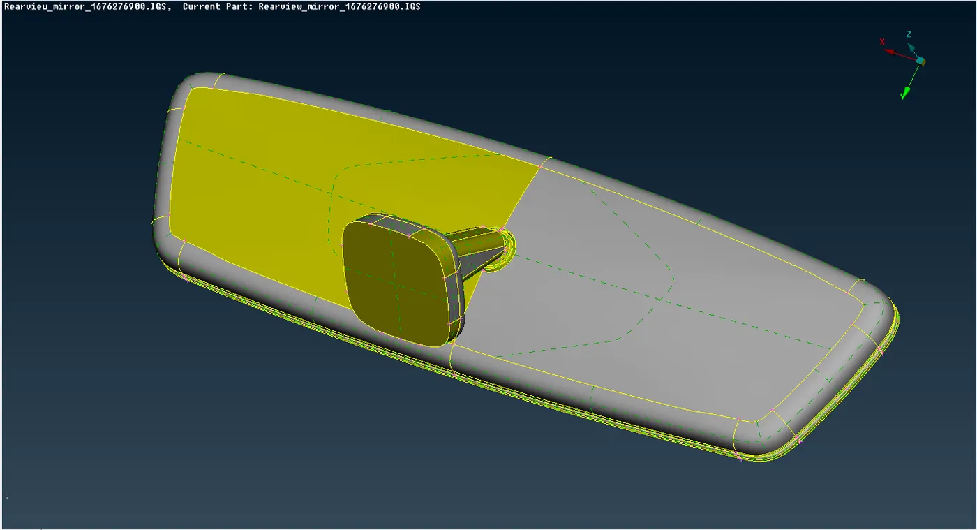
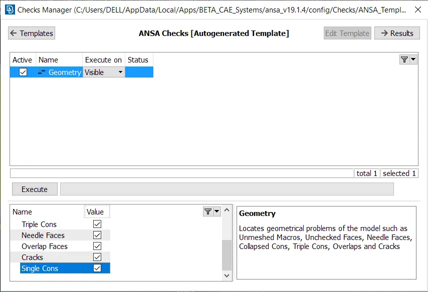
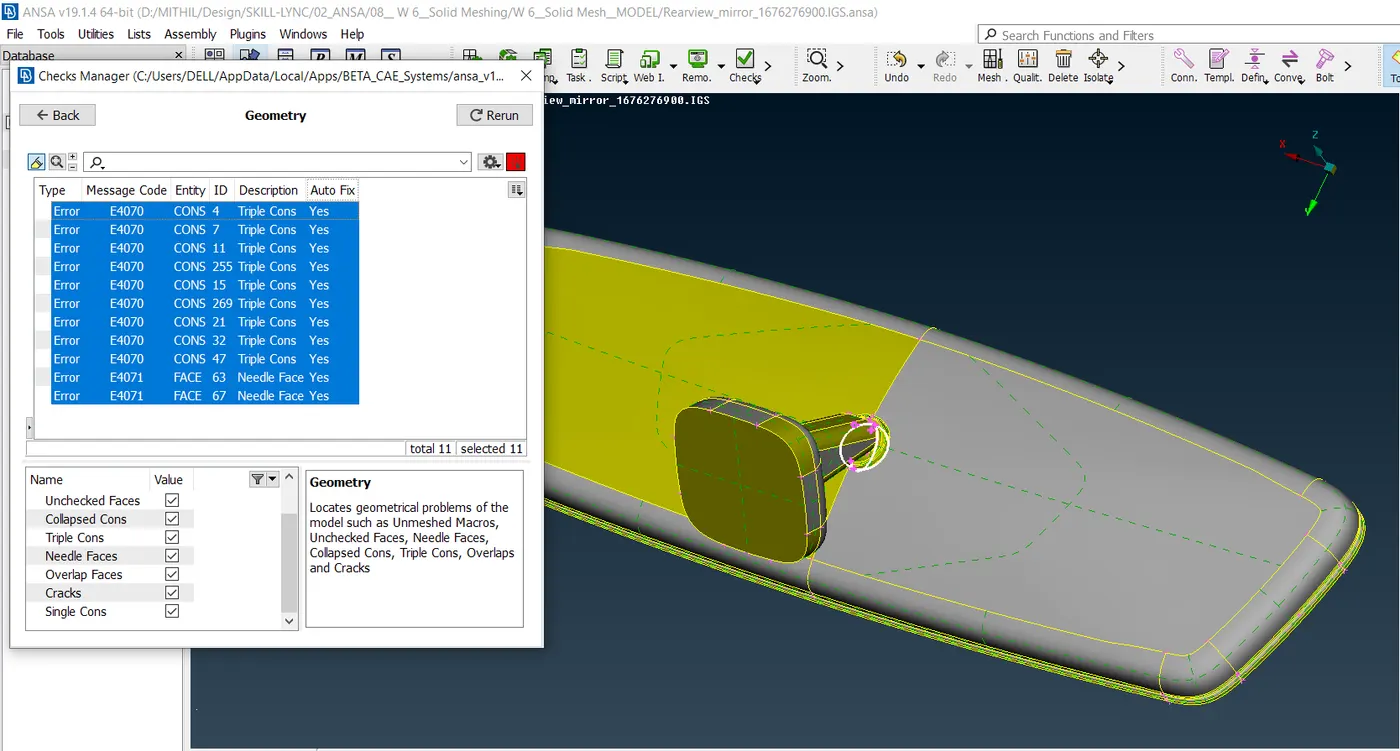
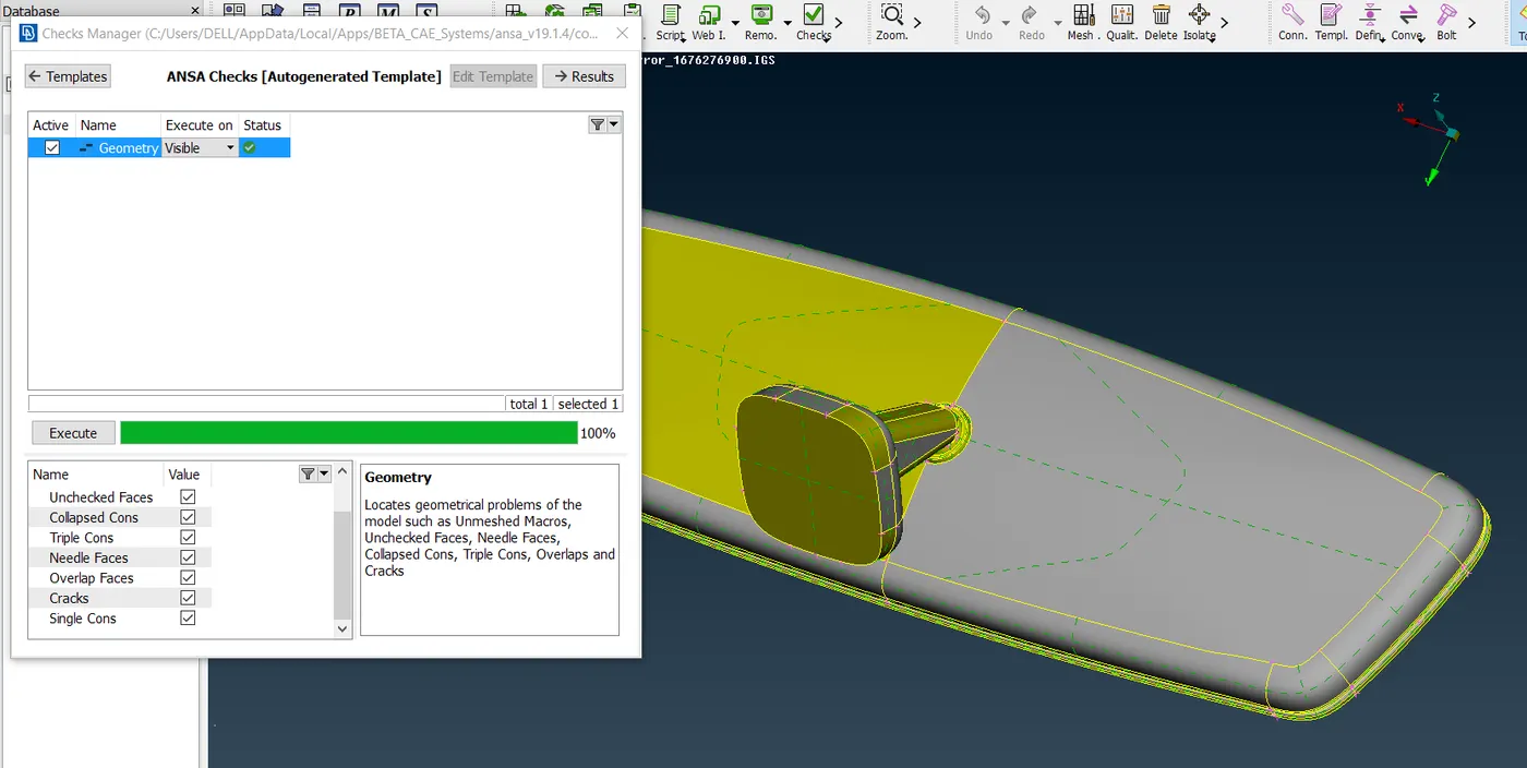
2. Now go to Checks tab à Geometry, to look for any defects in the model. After running the command fix any abnormalities if found and make component geometrically clean.
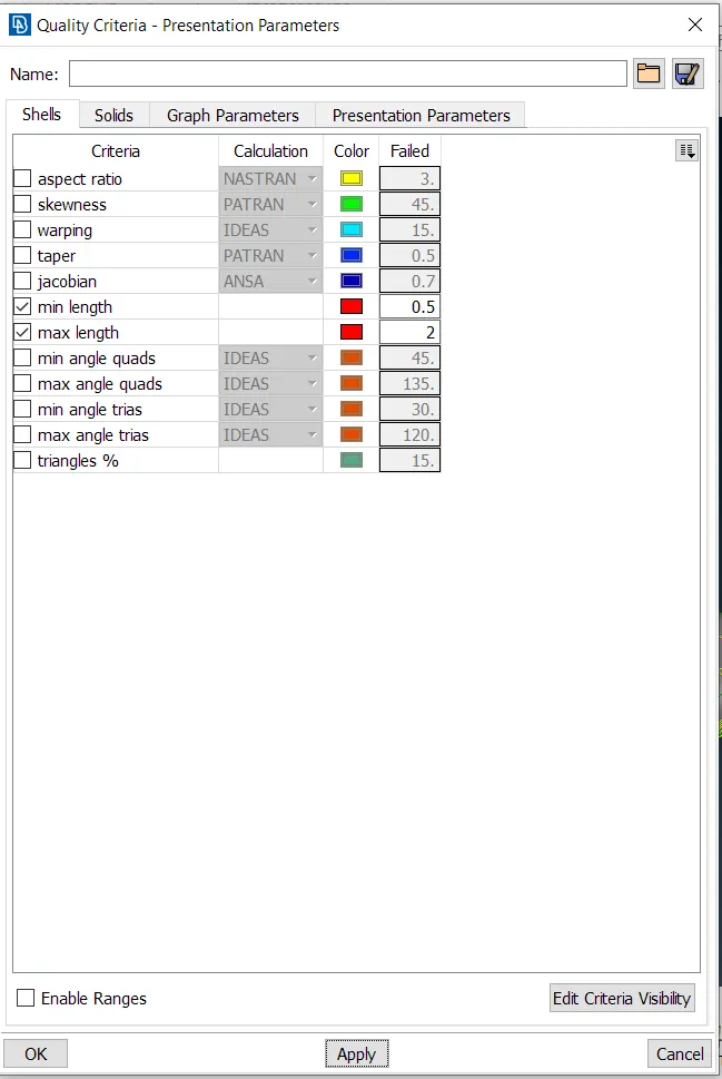
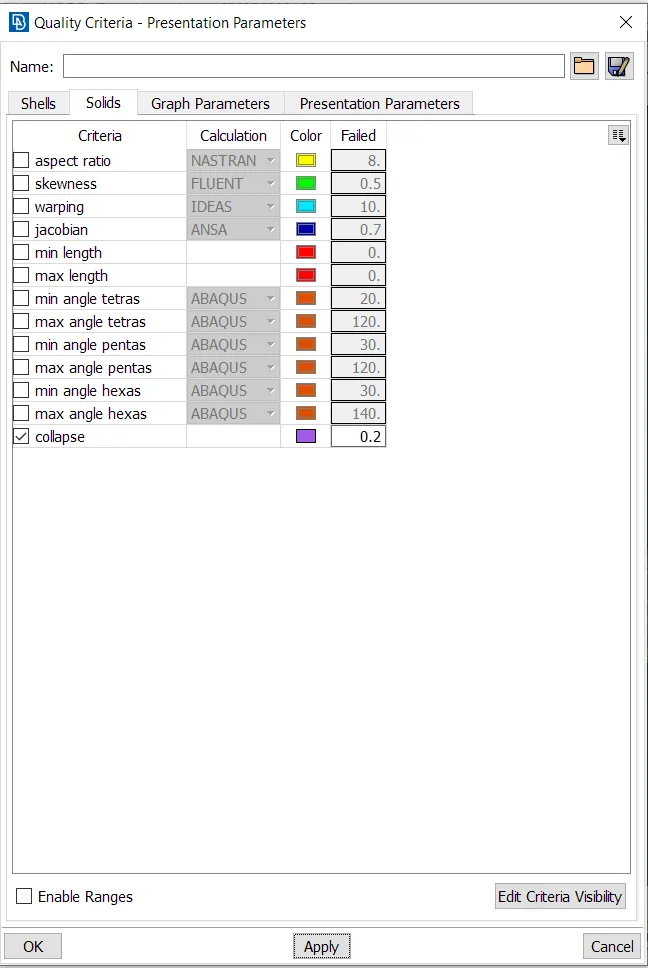
3. Now set the quality criteria for the meshing process as provided in the question, using Quality Criteria setting in Utilities Tab.
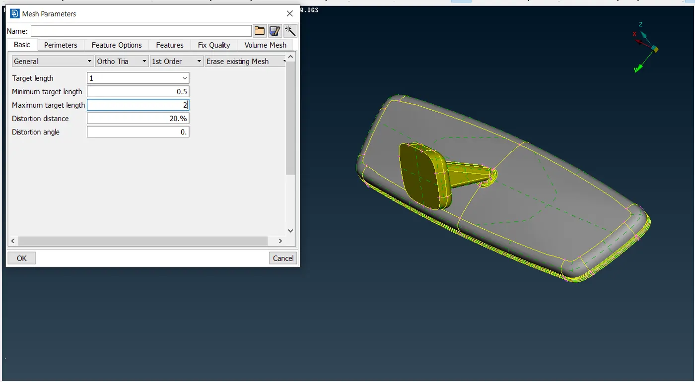
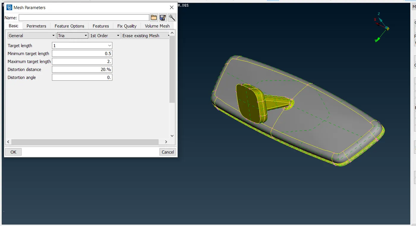
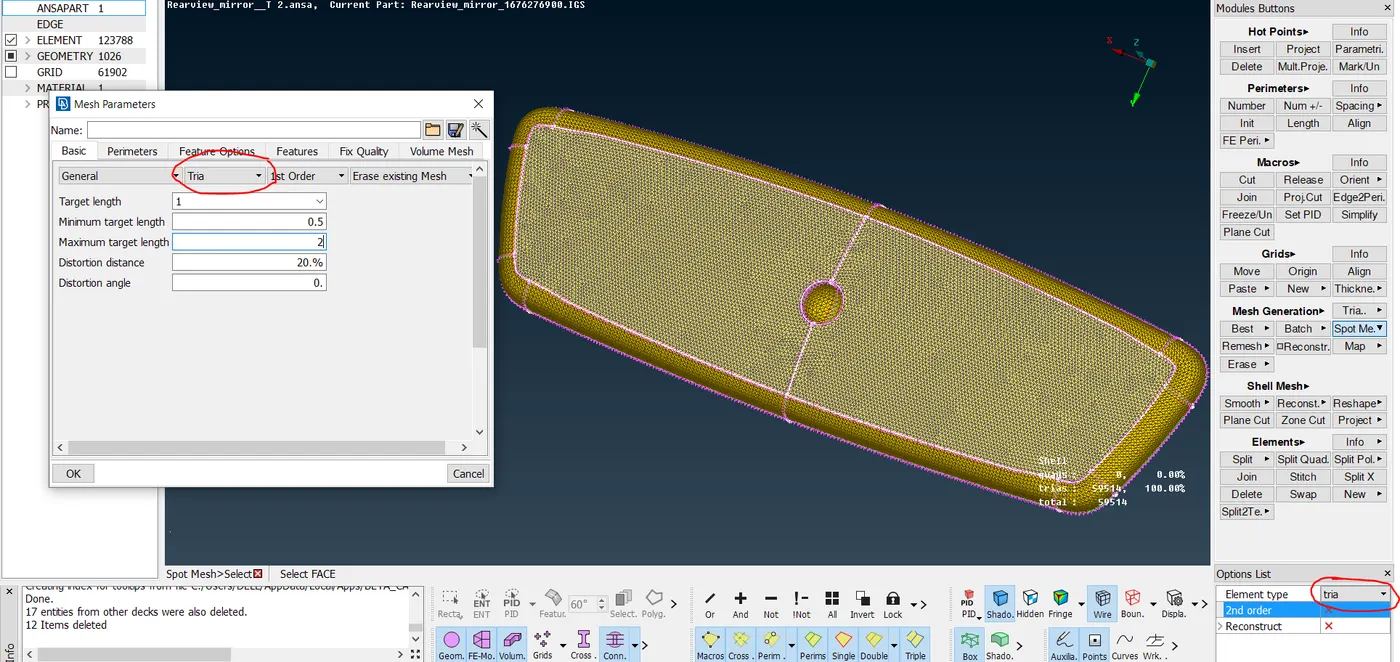
4. As our target element size is 1 mm, it is best practice to divide the edges of the part into small segments of 1 mm by using Length command in Parameters Tab as shown below:
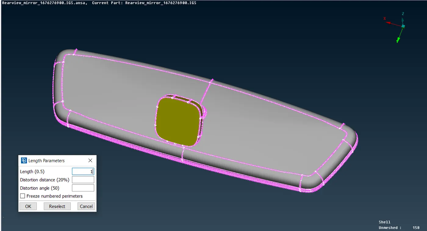
5. Now mesh the component using Spot-mesh command in Mesh Generation Tab. For a better mesh flow try to mesh the surface step by step instead of in one go.
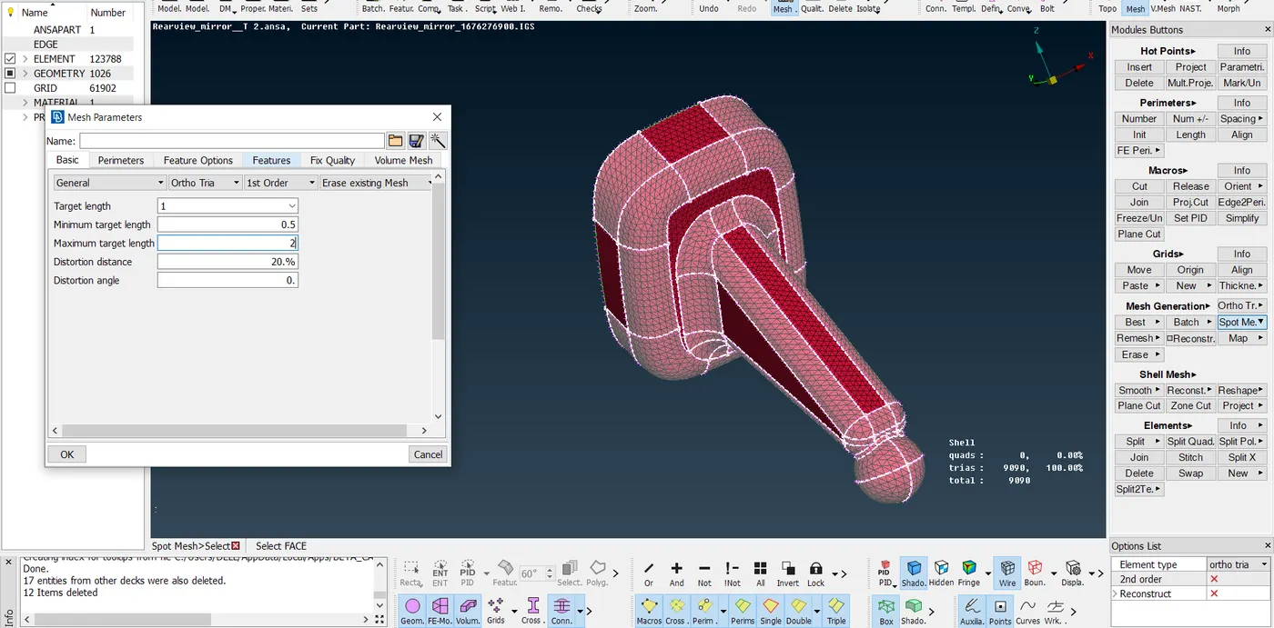
It is a stander practice to use Ortho Tria element to mesh any curve/ fillet/ complex surfaces of the component as it helps towards better feature capturing but it will also increase computational time of simulation.
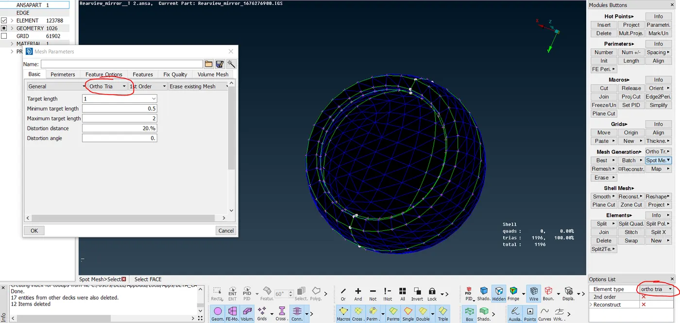
Use Tria elements for flat/ simple surfaces of the model for mesh generation since they required less computational time during simulation.
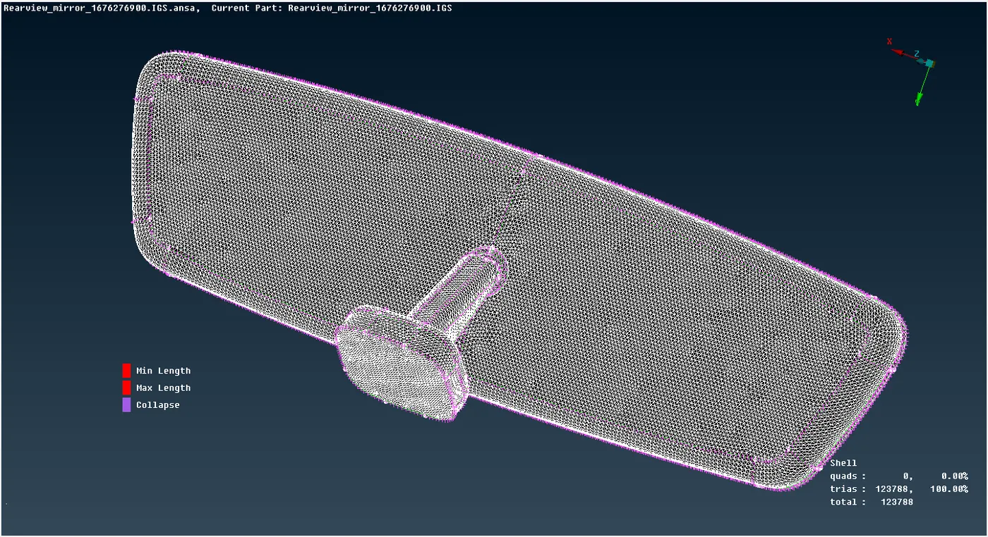
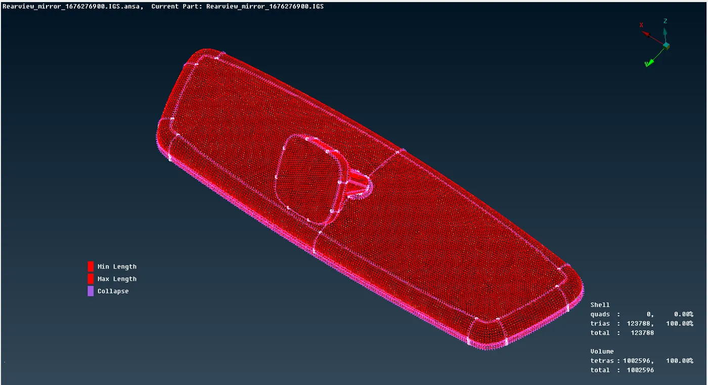
After meshing the component should look somewhat like this:
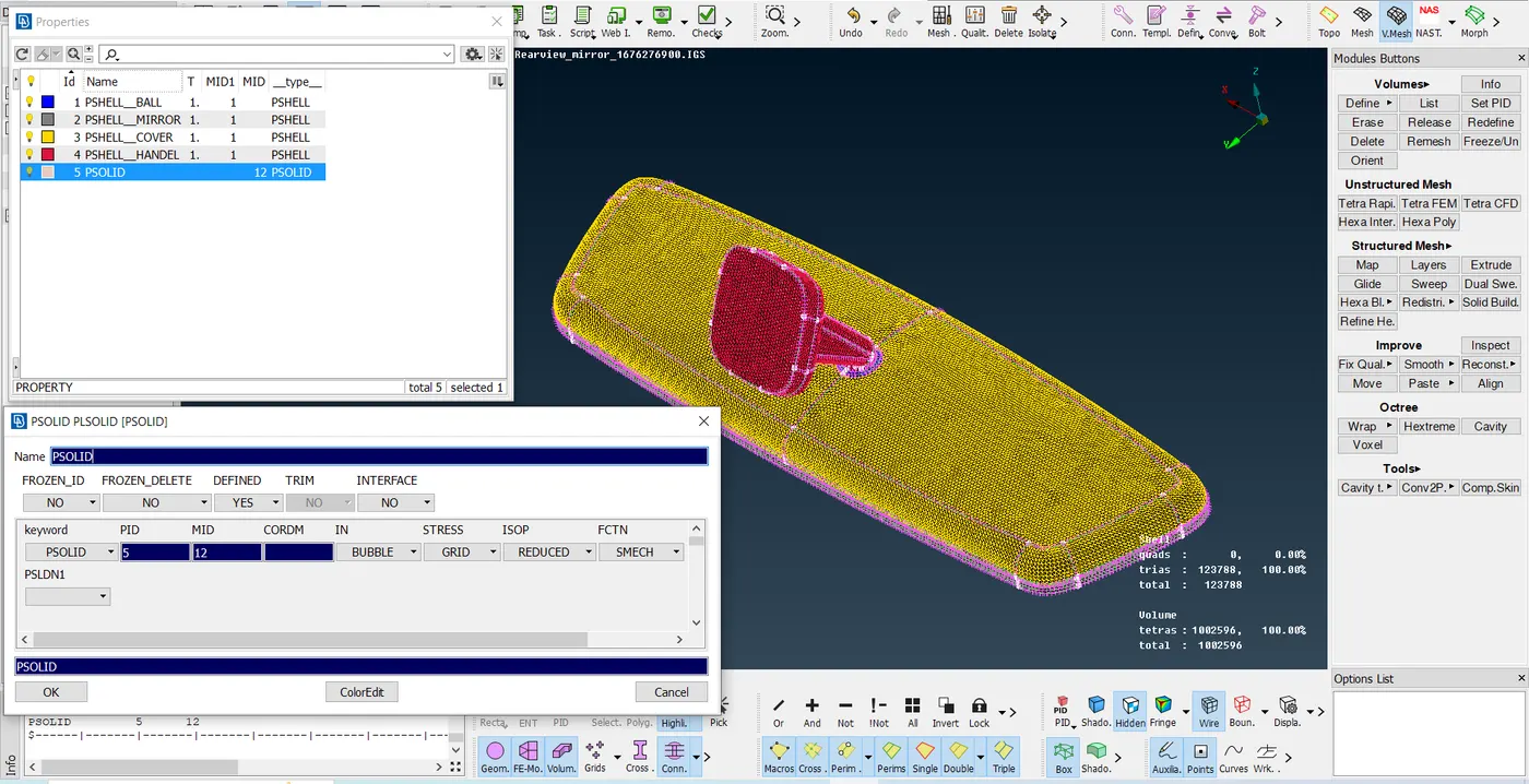
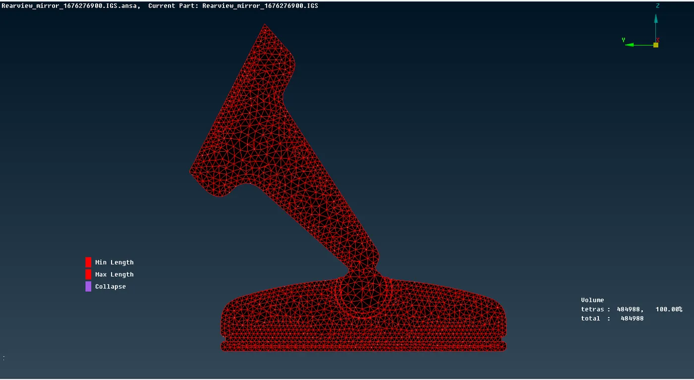
6. Now moving on to next step of generating 3D Tetra Elements using 2D mesh. Go to Volumes Tab à Define, select the component and run the command, on completion the 3D Tetra Mesh will look as shown below:
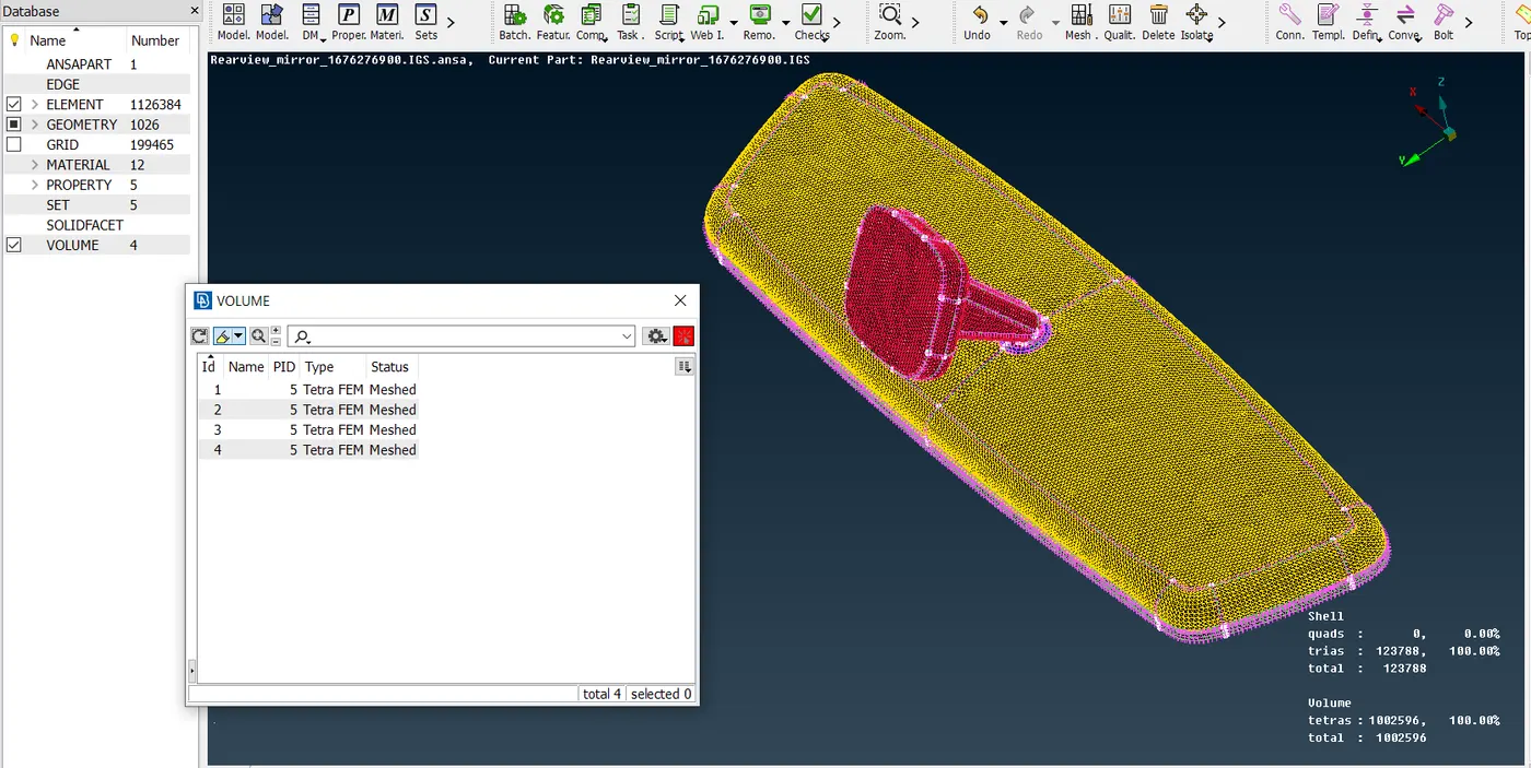
7. The final step is to look for any fail elements and fixing it as per quality criteria. For this we can use any of the two tools : Fix Quality Tool & MV Free Tool as per requirement. But as we can see the there are no Teat Collaps in the generated 3D Mesh.
8. Final model representation:
Conclusion: This project helps me to understand the methodology behind meshing of any Solid component. I learn some tools regarding 3D Tetra Meshing and how to assign volume to close shell elements. Also perform geometric and elemental clean up for both 2D & 3D elements.
[ NOTE: AS THE FILE SIZE IS > 20 MB I HAVE ATTACHED THE G-DRIVE LINK IN NOTE-PAD FILE. ]