Week 6 Modelling of Battery Pack
AIM :- Build a battery pack with 3S4P and 4S3P configuration with generic battery block
a.Configure the batteries as per a Lithium ion battery datasheet
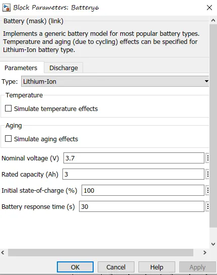
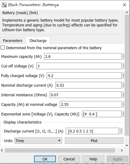
b.Explain your parameters
c.Simulate the model and comment on the results for SOC,voltage ,current in detail
d.Change the configuration to 4S3P and simulate the model
e.Compare the results for both model and give your explanation for the results
Batteries in Series and Parallel Explained
Batteries can either be connected in series, parallel or a combination of both. In a series circuit, electrons travel in one path and in the parallel circuit, they travel through many branches. The following sections will closely examine the series battery configuration and the parallel battery configuration.
1] Connecting Batteries in Series
A set of batteries are said to be connected in series when the positive terminal of one cell is connected to the negative terminal of the succeeding cell.
Advantages
Wiring batteries in series provides a higher system voltage resulting in a lower system current. Low current indicates that you can use thinner wiring and suffer less voltage drop in the system.
Disadvantages
In a series-connected battery system, a converter is needed to achieve low voltages.
2] Connecting Batteries in Parallel
A set of batteries are said to be connected in parallel when the positive terminals are connected in a battery, and similarly, negative terminals of these cells are connected. These combinations are referred to as parallel batteries.
Advantages
One of the prominent advantages of batteries connected in parallel is that if one of the batteries in the system fails to operate, the remaining batteries can still provide power
Disadvantages
Connecting batteries in parallel results in a higher current draw. This indicates thicker cables and more voltage drop.
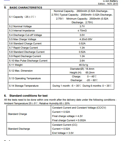
battery parameter of data sheet
battery inputparameter for simulation
SIMULINK MODEK FOR 3S4P AND 4S3P BATTERY MODEL
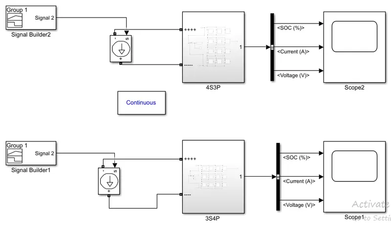
in the above figure signal builder produces the signal of an UDDS drive cycle , input is given to tthe controlled curent block which is connected to the battery system.
seprate signal builder block and seprate controlled curent block are provided to each sub system which contain the battery model.
BATTERY CONNECTION FOR 3S4P
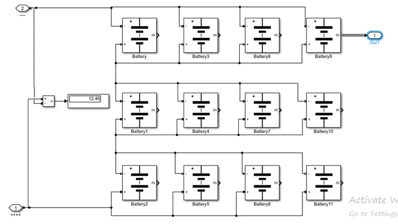
the above figure shows the the conection of 3Series and 4 parallel connection, we had also connected the volt meter which is showing the total voltage in it as 12.49 voltage.
calculation for voltage will be no of cell in parallel * max cell voltage
BATTERY CONNECTION FOR 4S3P
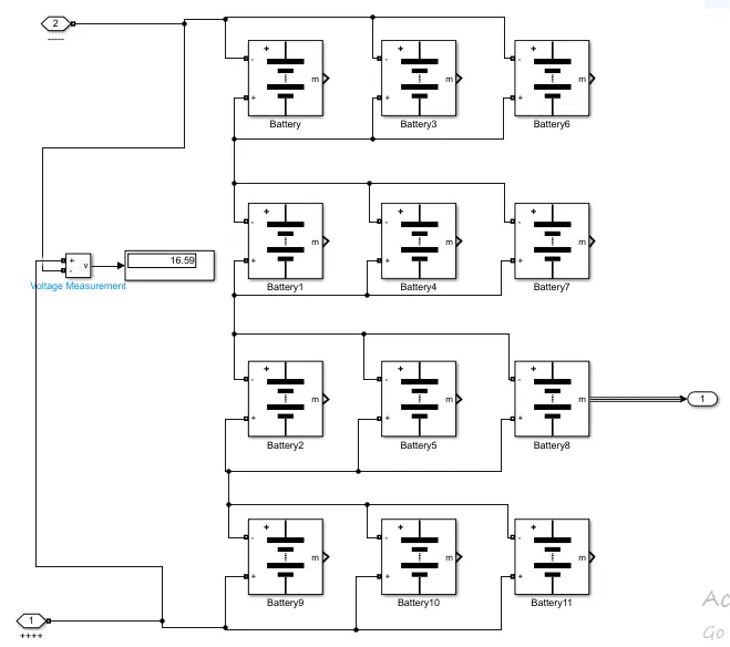
the above figure show the connection of 4Series and 3 parallel connection. we had also connected the volt meter which is showing the total voltage in it as 16.59 voltage.
output result
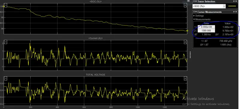
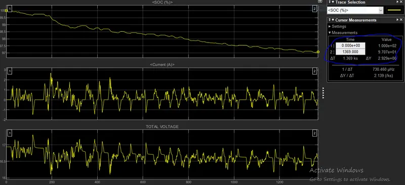
we have run the drive cycle for 1369 sec and we can see the results as
OUT OF 3S4P GENERIC BATTERY MODEL
OUTPUT OF 4S3P GENERIC BATTERY MODEL
COMPAIRASION
| 3S4P GENERIC BATTERY MODEL | 4S3P GENERIC BATTERY MODEL |
|
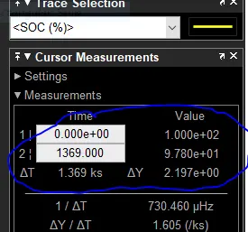
soc is decreased till 97.80 % when connected with 12 cell together
|
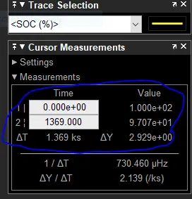
soc is decreased till 97.07 % when connected with 12 cell together
|
|
The entire current curve is similar to the drive cycle (which is a current vs time graph). the current can provide below 2A due to less voltage rate . |
The entire current curve is similar to the drive cycle (which is a current vs time graph). the current can provide above 2A due to high voltage rate . |
|
we can observe that we are getting less maximum voltage as 12.8v.with 12 cell |
where as w here we can get maximul current as 17v. with 12 cell |
so for battery with high voltage will have high current and soc drow will be less with respective to time in 4S3P battery configeration with total cell of 12.
THANK YOU