Week 6-Meshing of Hood Challenge
Aim:
a) Extract the mid-surface of the given hood model.
b) Clean-Up the geometry as per the requirement.
c) Mesh the hood model according to the given quality criteria.
Software used:
Software used for the given model is Altair- Hypermesh, a pre-processor used to mesh the model as per the quality.
Quality Required:
Target Element Length = 5 Units
| S.N | Quality Criteria | Value |
| 1 | Aspect Ratio | 5 |
| 2 | Skewness | 45 |
| 3 | Warping | 15 |
| 4 | Taper | 0.5 |
| 5 | Min. Length | 2 Units |
| 6 | Max. Length | 8 Units |
| 7 | Min angle Quad | 45 |
| 8 | Max angle Quad | 135 |
| 9 | Min angle Tria | 20 |
| 10 | Max angle Tria | 120 |
| 10 | Tria % | 10 |
Procedure:
Importing the CAD _Model
a) Open the given model in the hypermesh software in its readable format such as .stp, .iges, .hm.
b) Once the model is imported, the model is checked properly to avoid any missing surfaces, any duplicates, and so on.
c) In hypermesh, before extracting mid-surface the solid part is deleted for each component. Use 'delete' option > select 'solid'> select 'displayed'> 'delete entity.
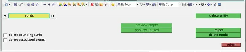
fig. 1 Deleting solids from each component
Geometry Clean_Up
d) After deleting the solids, the shell components have to be cleaned up based on the complexity of the model. In fact, the model is prepared for meshing by suppressing unnecessary triple cons.
e) Automatic clean-up is not recommended as it suppresses some of the critical lines or fillets.
Mid_surface Generation
f) In order to extract the mid-surface manually, the thickness of each component is measured. The thickness of the component decides whether to go for solid meshing or shell meshing. The threshold value for thickness is usually 5mm.
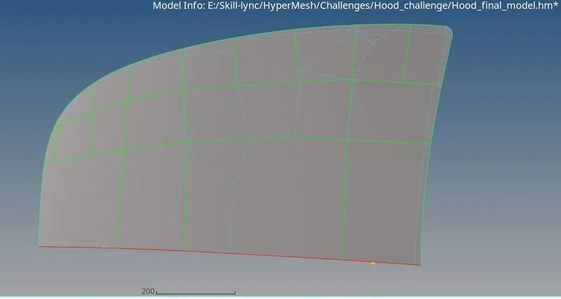
fig. 2 Mid-surface of the outer hood extract
g) The given model has a thickness of less than 5, hence shell meshing is preferred.
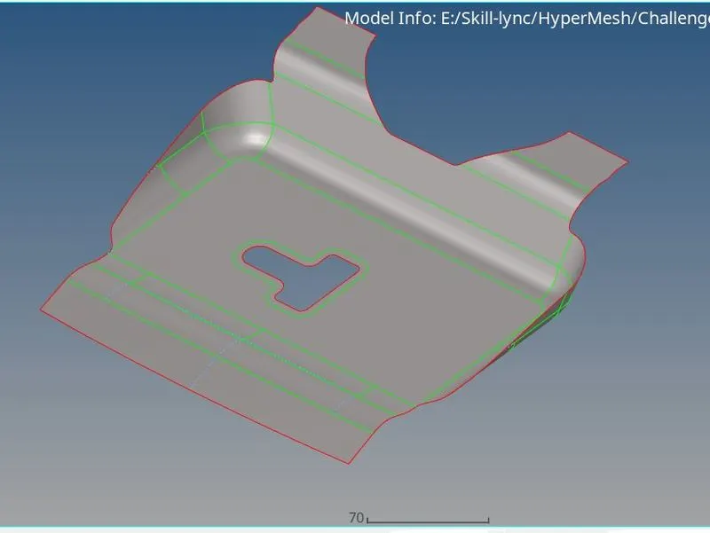
fig. 3 Mid-surface of latch reinforcement extract
h) To extract the mid-surface, the steps to be followed are 'Geometry'> 'mid surface > 'Automid' ( gives automatic mid-surface). Also, there are a few manual extraction options such as 'skin offset', 'offset', 'offset+planes', 'offset+planes+sweep'. The option is chosen based on the complexity of the model.
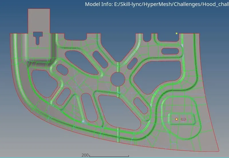
fig.4 Mid-surface of inner hood_extract
i) The components having a symmetrical geometry are halved and one of the two halves is deleted. Also, manual cuts are created in the mid-surface geometry for the ease of meshing.
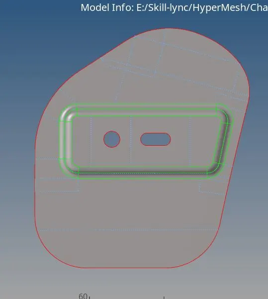
fig. 5 Mid-surface of hinge reinforcement extract
Meshing
j) The components are individually meshed. Before meshing a particular component set the 'element size' and 'mesh type' to 5mm and mixed respectively.
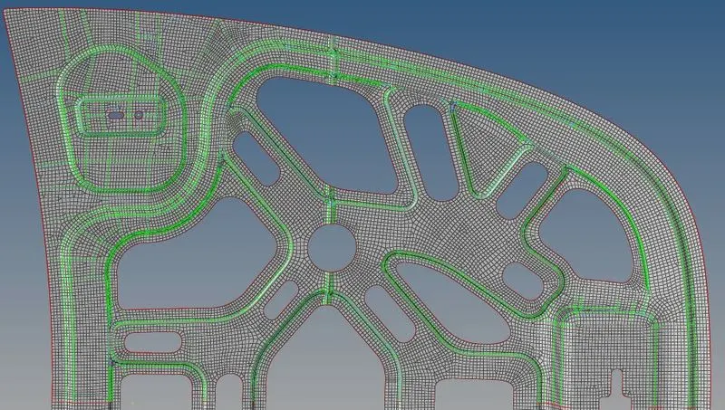
fig. 6 Meshed inner hood extract
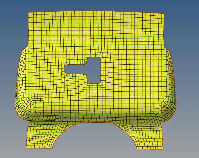
fig. 7 Meshed latch model
k) The steps to mesh a component; '2D'> 'Automesh'> select the 'surface' and 'mesh' the selected surface.
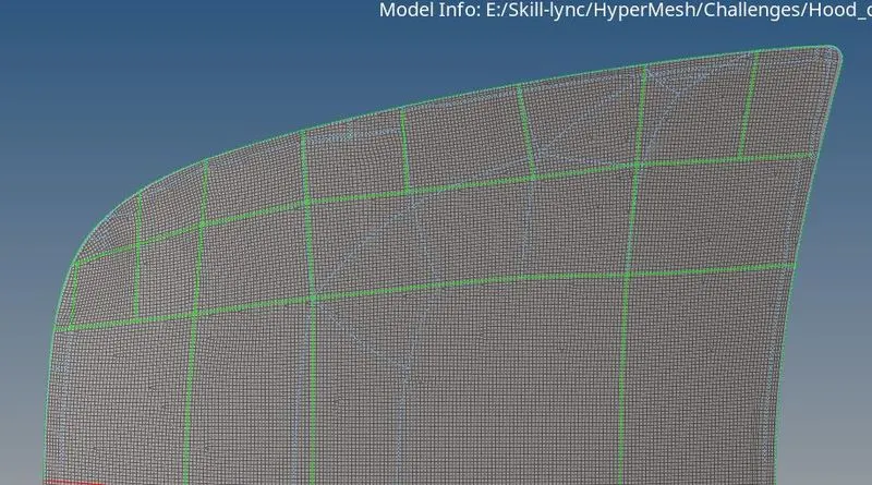
fig. 8 Meshed outer hood extract
l) The component should be meshed according to the quality criteria given. The criteria are set in 'criteria file setting' in 'preferences' options.
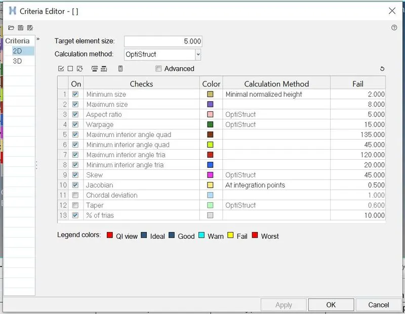
fig. 9 Setting Quality criteria in criteria editor.
m) While meshing, feature capturing is given prime importance. Moreover, opposite trias, rotating quads, pattern trias, and element failures should be as minimum as possible.
n) Likewise, nodes should be kept on edges, and the mesh should have a uniform flow.
o) There are a few tools such as 'drag tria', 'smooth', 'swap', 'split edge', 'split quad', and so on that are mostly used for mesh improvement.
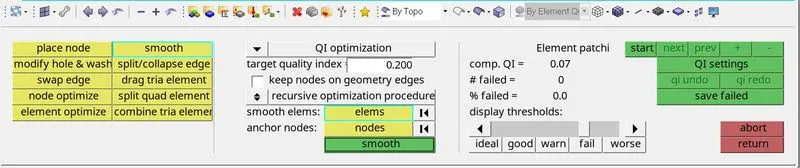
fig.10 Quality index tab used for mesh improvement
p) Most of the 'warpage' and 'minimum and maximum size' failures are handled using the translate tool and distance option.
q) The hood model is pre-processed with '0' elemental failure. The final model has no elements violating the threshold value.
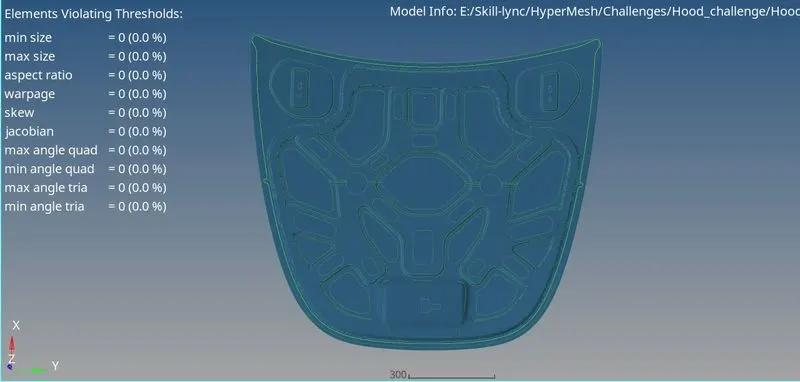
fig. 11 No elements are violating the threshold value
r) Once after creating a good mesh flow, the meshed components having symmetrical geometry are reflected to get the complete meshed model. The 'free edge' formed after reflecting the model is removed by performing an 'equivalence' operation.
s) Finally, the meshed model is assigned with the required thickness. The new property is created for different thicknesses, and the respective property is assigned to the corresponding meshed model.
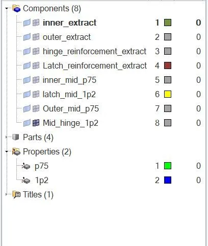
fig.12 Mesh assigned with thickness value.
Learning outcome:
a) Learned to perform manual clean-up
b) Learned to take the mid surface of component
c) learned to mesh a component.
d) Learned to assign thickness to the component.
e) Learned to address quality issues.
f) Learned to reflect the mesh.
g) Learned to remove free edges.
h) Explored several options to generate a uniform mesh flow.
Result:
a) Mid-surface of the model is extracted successfully.
b) The cleaned-up geometry is meshed successfully with the required quality.
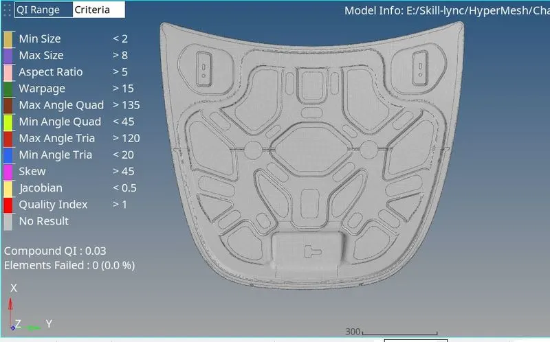
fig. 13 Hood model meshed successfully