Project - 2 - Meshing on the suspension Assembly
Aim:
For the given Suspension Assembly
a) Check for the geometrical errors
b) Mesh with the given set of quality criteria
c) Thickness has to be assigned for mid-surface components
d) Non-Uniform thickness components should be meshed using tetra elements
e) Connection has to be made where it is required
Procedure:
a) The given model is opened in ANSA, post which the length of the perimeter and the macro is set to 1mm for better refinement purpose.
b) 'Topo' is given to each component in order to stitch the unstitched surfaces.
c) Each component in the system is given a proper orientation using 'orient'.
d)) The entire model is checked component by component for geometrical errors, and issues such as triple cons, single cons, unchecked faces are addressed manually and the remaining errors such as needle faces, cracks overlap and so on are fixed automatically.
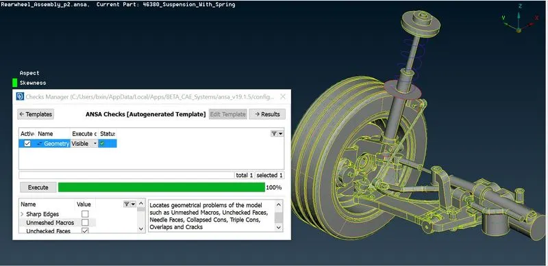
Fig. 1.1 Geometry check-up for the suspension system
Case 1:
Quality Criteria for Tria Elements (Tyre and Rim):
|
S.No |
Quality Criteria |
Value |
|
1 |
Average length |
6.5 |
|
2 |
Minimum Length |
5 |
|
3 |
Maximum Length |
10 |
|
4 |
Skewness |
45 |
Quality Criteria for Tetra elements:
|
S.No |
Quality Criteria |
Value |
|
1 |
Tet-collapse |
0.2 |
Geometry Clean Up and Shell Mesh generation with Batch Mesh
a) Tyre and rim are separately checked for geometrical errors and are addressed accordingly as mentioned in the above procedure.
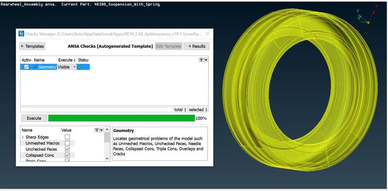
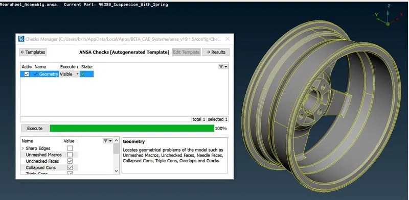
fig. 1.2 Tyre and rim, after being properly addressed for geometrical errors.
b) After geometric cleanup, both the tyre and rim are batch meshed using the tria and ortho tria elements against the given set of quality and mesh parameters.
c) Tyre and rim components are batch meshed where ANSA automatically runs a mesh with the required quality criteria and saves a lot of time.
d) In order to perform a batch Mesh, a new meshing scenario is created and the component that has to mesh is added to it. Quality criteria and mesh parameters are assigned accordingly to the scenario followed by 'run' to create a batch mesh.
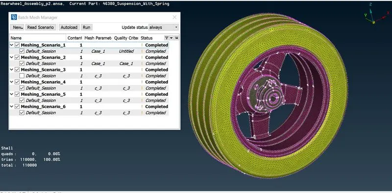
fig. 1.3 Tyre components meshed with batch mesh
e) Ortho tria is used to capture the curved features more precisely, while tria elements are used on flat surfaces. However, tria elements are used to capture most of the surfaces (including curved), as it would capture the surface without maximum length failure.
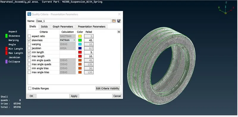
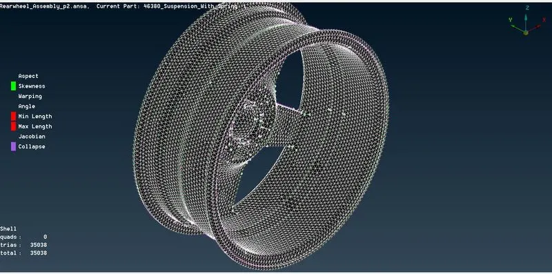
fig. 1.4 Shell mesh applied over the tyre and rim with the case_1 quality criteria and mesh parameters
Volume Mesh Generation with Tetra FEM and Tetra Rapid
a) A volume is defined in the volume mesh for the tyre and rim and both are solid meshed with tetra Rapid and tetra FEM elements respectively. Both the algorithm generates tetrahedral mesh inside the volume, however, tetra FEM has structural application.
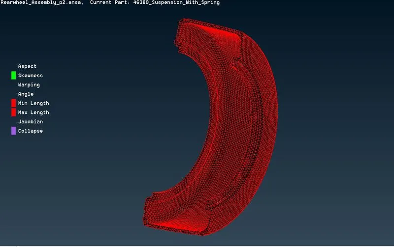
fig. 1.5 Tyre volume meshed with tetra Rapid elements
b) There were a few 'tet collapse' which are fixed manually using 'move' option.
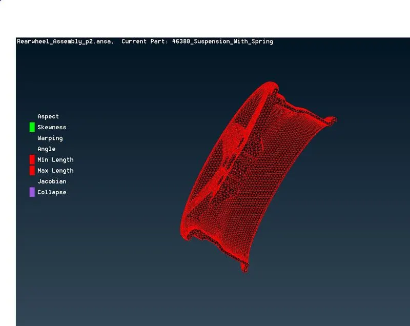
fig. 1.6 Rim volume meshed with tetra FEM elements
c) Quality check is made for the tyre and rim according to case_1 quality criteria.
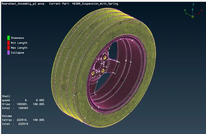
fig. 1.7 Quality Check for case_1
Case 2: (C_2)
Quality criteria for Mixed elements (For Midsurface only):
|
S.No |
Quality Criteria |
Value |
|
1 |
Target/Average length |
4 |
|
2 |
Minimum Length |
2 |
|
3 |
Maximum Length |
6 |
|
4 |
Aspect |
3 |
|
5 |
Warpage |
15 |
|
6 |
Skewness |
45 |
|
7 |
Jacobian |
0.7 |
|
8 |
Minimum Quad Angle |
45 |
|
9 |
Maximum Quad Angle |
135 |
|
10 |
Minimum Tria Angle |
30 |
|
11 |
Maximum Tria Angle |
120 |
Topology Clean Up and Midsurface Generation
a) Mid-surface has to be taken for components having a thickness less than 5. In this case, 2 (represented as 'c_2') the mid surface of components are taken using 'offset' option.
b) Geometry check is initially performed on the components and are made error-free.
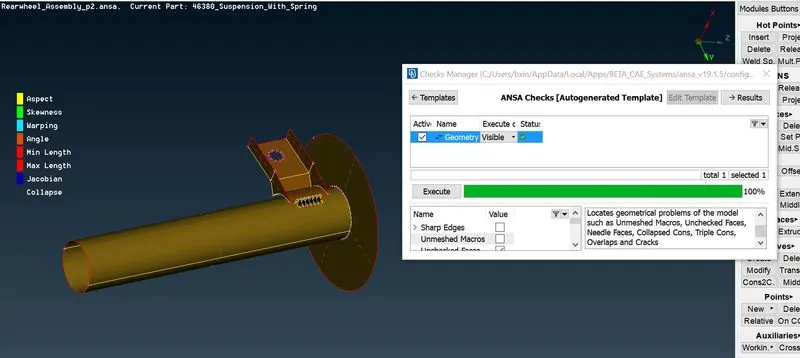
fig. 2.1 Geometry checks performed
c) The component is shell meshed according to the given quality criteria (c_2).
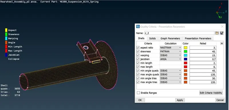
fig. 2.2 The mid-surface has meshed against c_2 quality criteria.
d) Once shell meshed, the mid component is drawn as solid by assigning thickness to it.
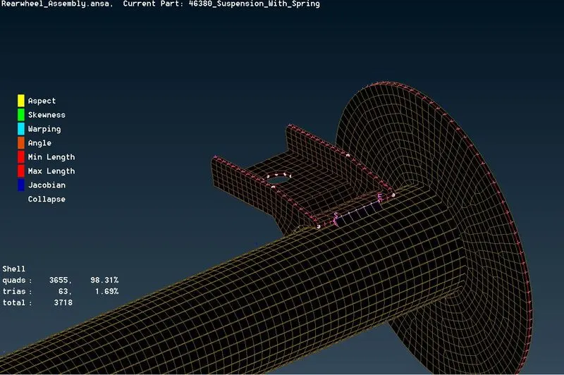
fig. 2.3 Midsurface assigned with a thickness
e) Quality check is made for the mid surface components as per case_2 quality criteria.
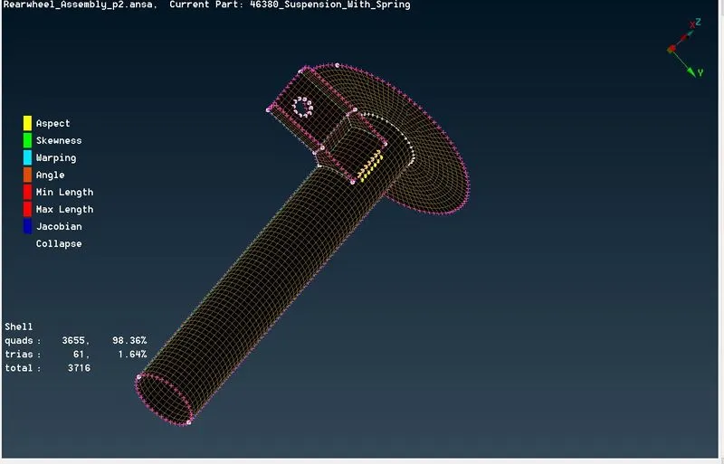
fig. 2.4 Quality check for case_2
Case 3:(c_3)
Quality criteria for Tria (For other components):
|
S.No |
Quality Criteria |
Value |
|
1 |
Target/Average length |
4 |
|
2 |
Minimum Length |
2 |
|
3 |
Maximum Length |
6 |
|
4 |
Skewness |
45 |
Quality Criteria for Tetra elements:
|
S.No |
Quality Criteria |
Value |
|
1 |
Tet-collapse |
0.2 |
Topology Clean Up
a) The remaining components of non-uniform thickness is individually checked for geometry and errors are addressed accordingly.
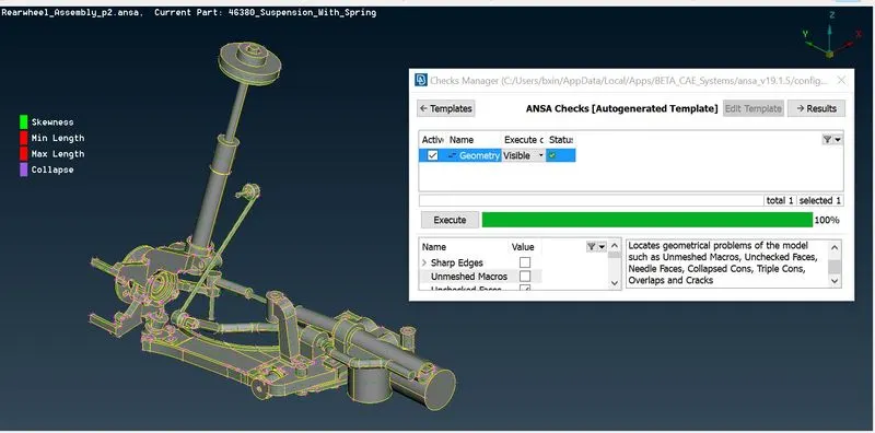
fig. 3.1 Geometry check on components
Shell Mesh Generation
a) The mesh generation is done mostly using spot mesh with reconstruction option enabled, while some of the components are batch meshed where ANSA automatically does geometry clean up and suppresses many of the feature lines to meet the quality. Hence, only a few errors are left for manual correction.
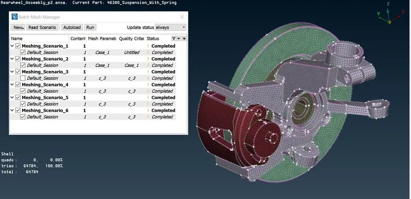
fig. 3.2 Batch Meshing performed on a few of components
b) The components are shell meshed individually against c_3 quality criteria.
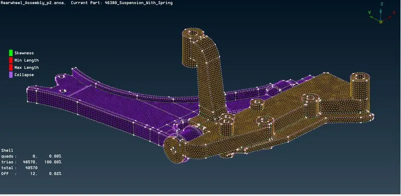
fig. 3.3 shell meshed w.r.t the c_3 quality
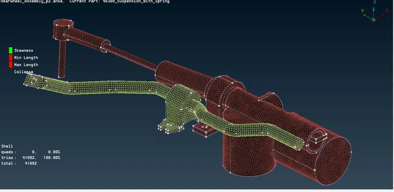
fig. 3.4 shell meshed w.r.t c_3 quality criteria
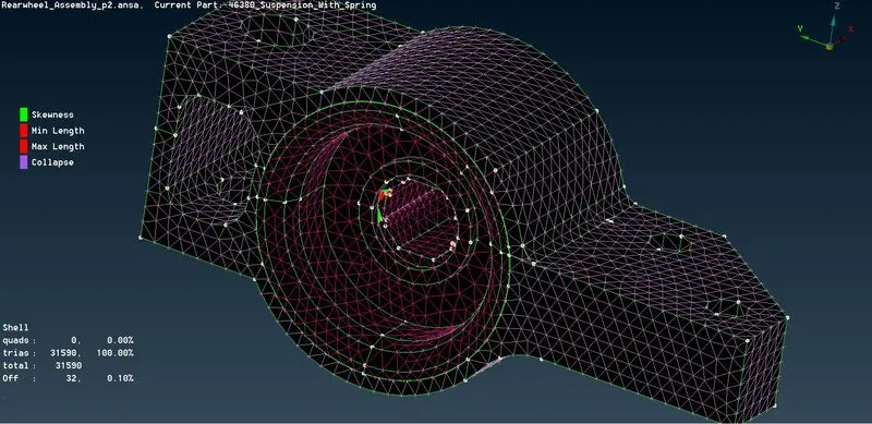
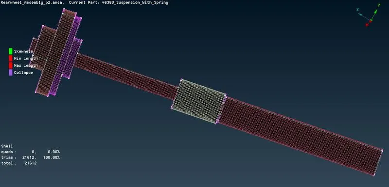
fig. 3.5 components shell meshed
c) Individual P_Shell Id created for the components.
Volume Mesh Generation
a) Once shell meshed, the volume is defined for individual components, post which 'P_Solid ID' is created for individual components.
b) The volume is then meshed using 'Tetra Rapid' and Tetra 'FEM' algorithms.
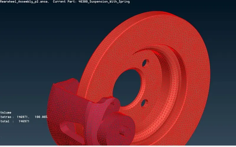
fig. 3.6 Volume Mesh for braking components
c) The volume mesh is checked for 'tet collapse' of 0.2 and most of the elements are passed the quality in most of the cases. On very few components a few 'tet collapse' appeared, and were addressed manually without any 'kinks' or 'dents'.
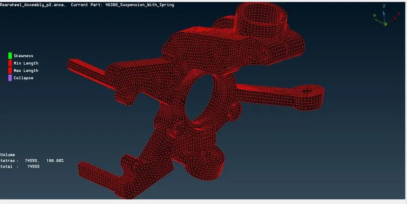
fig. 3.7 Meshed Knuckle volume
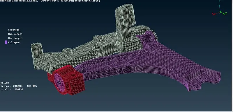
fig. 3.8 Volume Meshed components
d) Quality check is made for the components shown in the below figure.
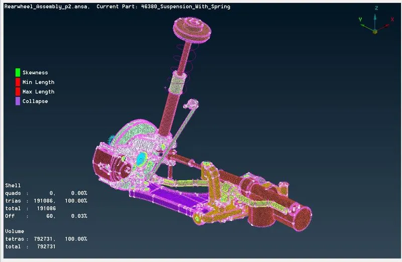
fig. 3.9 quality check for case_3.
Representing Spring with 1D-Bar elements
a) A mid curve is generated for the spring using the option Curves> Middle. After which the curves are connected using the option Curves> Multi connect which connects all the individually created curves to a single curve.
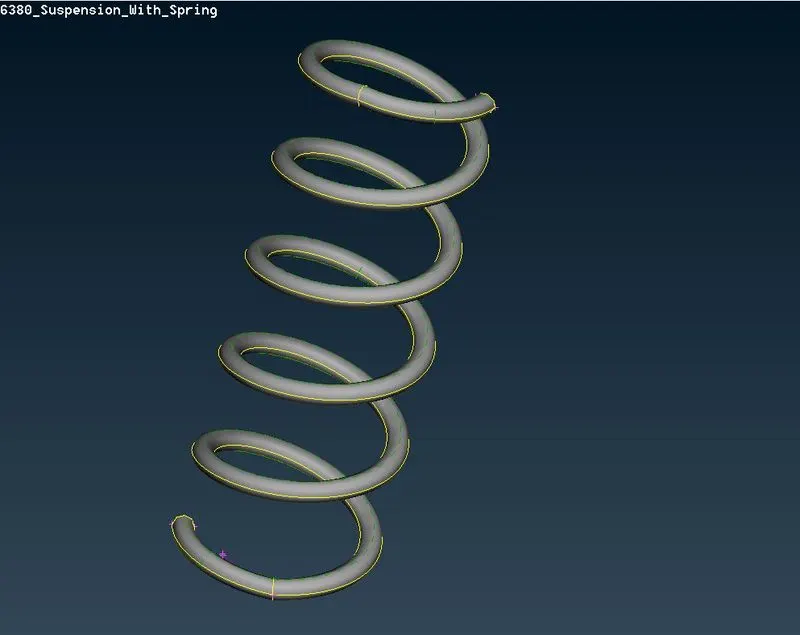
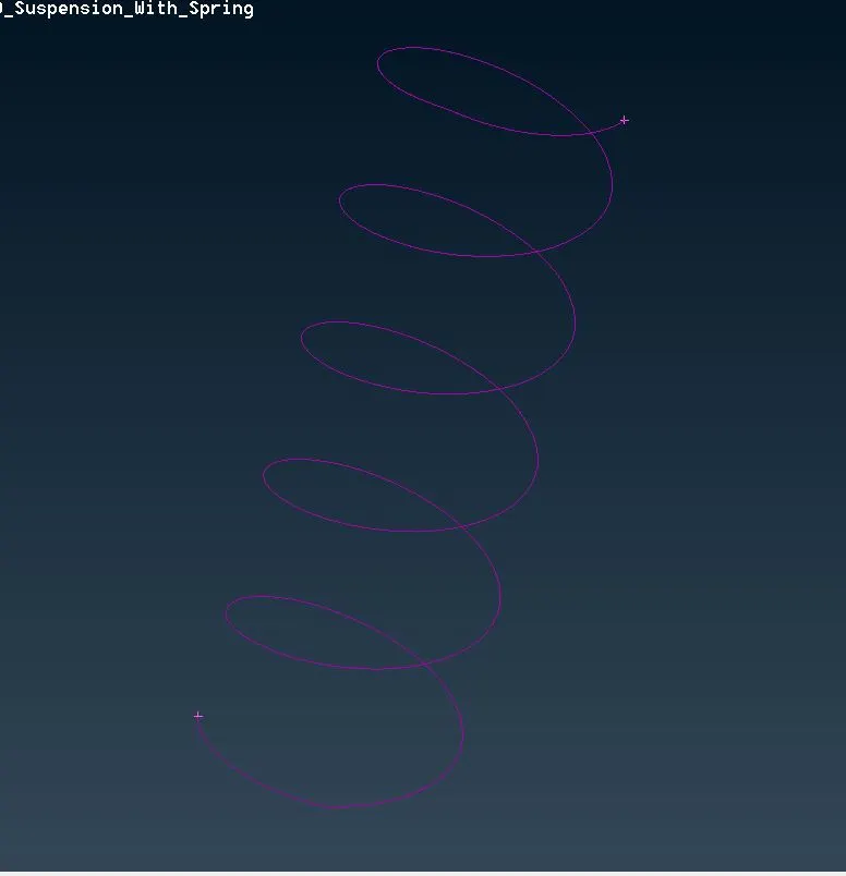
fig. 4.1 Mid curve is generated for the coil spring
b) After generating the curve, a 'COG' point is defined for that curve to define an orientation.
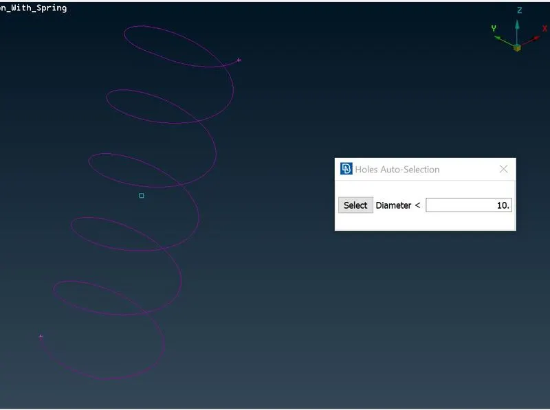
fig. 4.2 COG point defined for the curve
c) In the 'NASTRAN' deck, select the 'CBAR' element, then enable 'orientation with node' box along with this switch the selection to the curve(box).
d) After which select the curve and confirm the selection, then select the COG that was created for the curve.
e) Specify the 'element length' as required for the CBAR, and here it is set to 4mm as given.
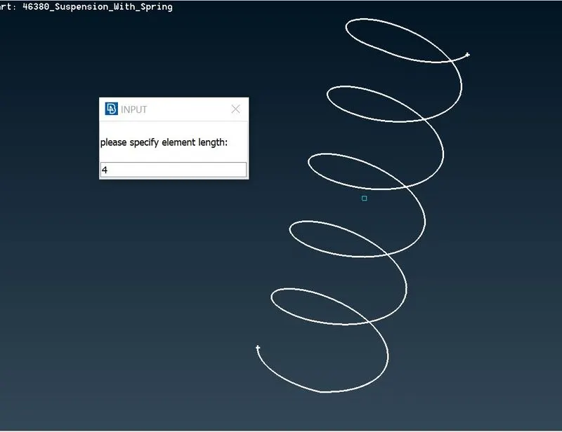
fig. 4.3 Element length specified for the CBAR
f) Then create a new property ID and CBAR ID for the spring, and assign a radius for the CBAR.
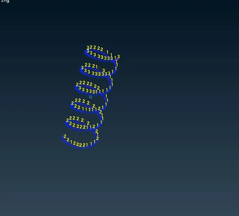
fig. 4.4 I-D representation of the spring
g) To represent 1D bar as 3D, check the line element cross-section as solid in presentation parameters.
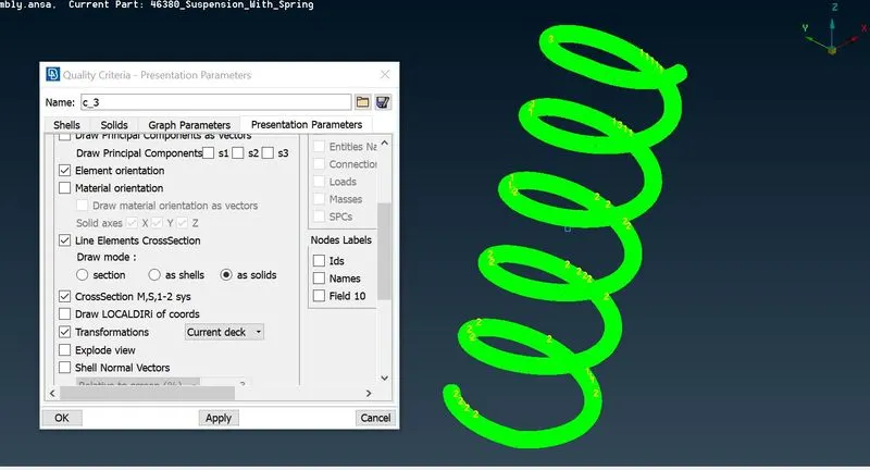
fig. 4.5 Solid representation of the CBAR elements
Connections Representation
a) The meshed suspension system has many connection areas which can be represented as per the type of connections required at that particular area.
b) Seam weld connection is established in a particular area, where the reference curve is created and the curve is then converted to seamline for seam welding.
c) The generated seamline is then realised as seam weld in connection manager by applying an overlap shell as the FE type in the connection manager dialogue box.
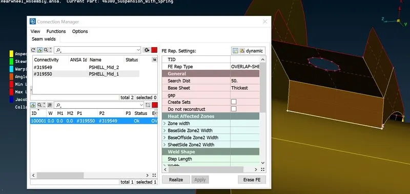
fig. 5.1 converting seam line to seam weld type connection
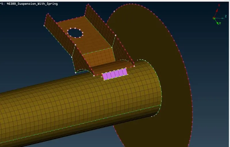
fig. 5.2 seam weld connection deployed
d) Most of the remaining portions are established with an RBE2 type of connections with many nodes and single node RBE2. This is done to rigidise the areas where the connections are supposed to be made.
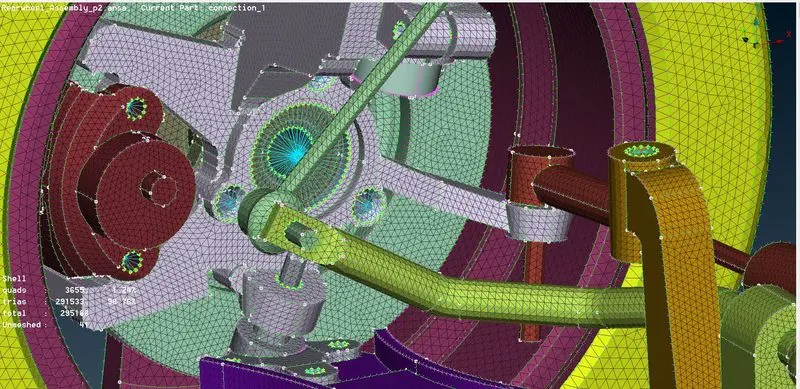
fig. 5.3 Connections deployed on the suspension assembly
Learning Outcomes
a) Learned to work on complex geometries such as suspension assembly.
b) learned to remove geometrical errors from the geometry by manual intervention.
c) learned to generate mid surface by offset surface, also learned to identify those components where the mid surface is required.
d) learned to perform batch meshing, and to address the off elements manually.
e) learned to generate volume mesh by different means, moreover learned to remove 'tet collapse' from volume mesh.
f) Learned to establish different connections in the required areas.
Conclusion
a) The assembly is checked for geometrical errors.
b) The components are meshed according to the given three cases of quality.
c) Thickness assigned to the mid surface where it is required.
d) connections established as per the requirement.