Week 6-Meshing of Hood Challenge
Objective:
Follow the below-mentioned quality criteria, mesh the component given below and assign thickness:
Target Element Length = 5 Units
| S.N | Quality Criteria | Value |
| 1 | Aspect Ratio | 5 |
| 2 | Skewness | 45 |
| 3 | Warping | 15 |
| 4 | Taper | 0.5 |
| 5 | Min. Length | 2 Units |
| 6 | Max. Length | 8 Units |
| 7 | Min angle Quad | 45 |
| 8 | Max angle Quad | 135 |
| 9 | Min angle Tria | 20 |
| 10 | Max angle Tria | 120 |
| 10 | Tria % | 10 |
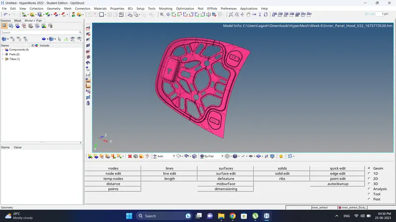
Cad Model Image:
Initail
Procedure:
1. Open the Model.
2. Go to Geometry-Mid surface, select surface and create a Mid surface.
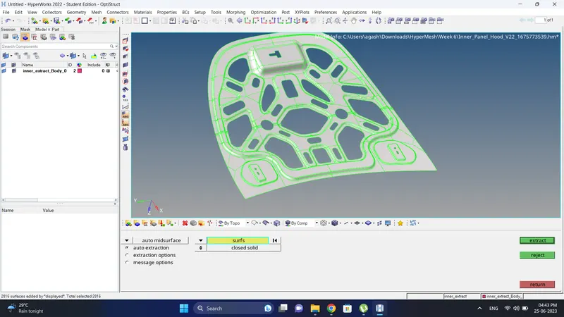
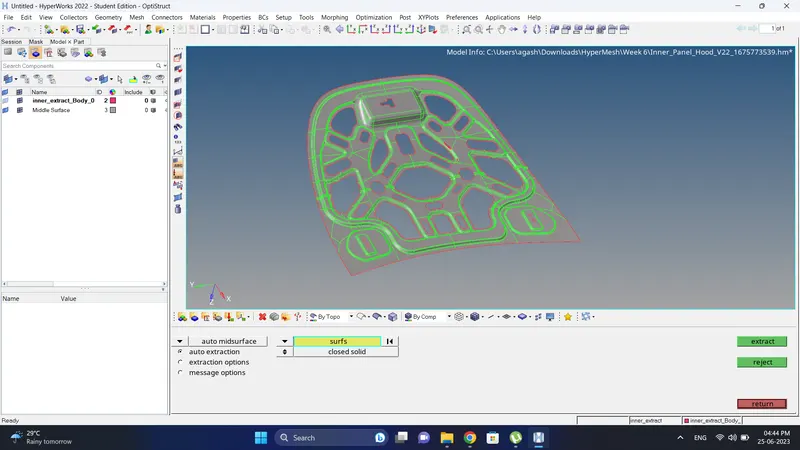
3. Check the mid surface geometry and fix it.
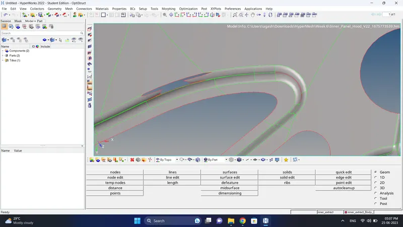
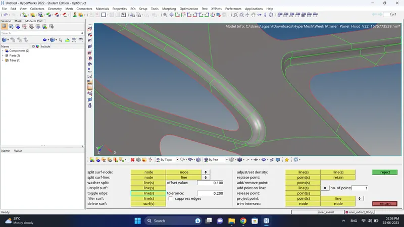
4. Since its a symmetric model, we can cut the model from middle using Geometry-Quick edit-Split surf line, to use this option we can select line or node, since the line already present click on the line and the next edge to split the surface.
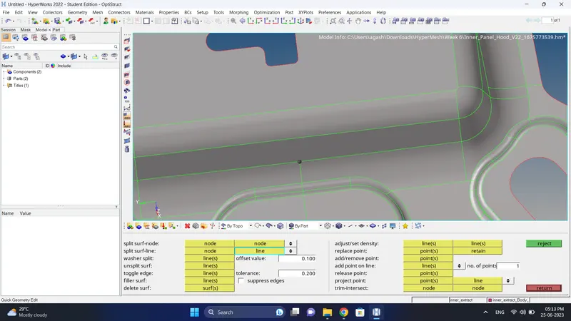
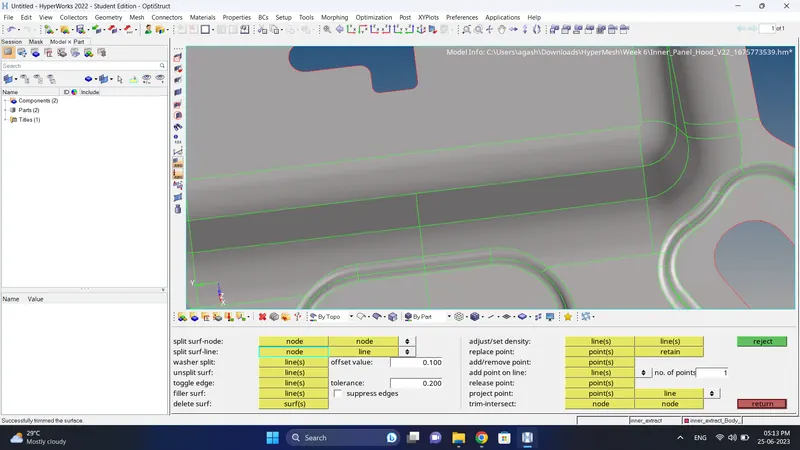
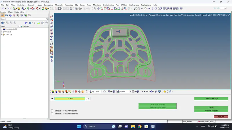
5. After splitting the surface delete the half symmetric side using Delete-surfs option.
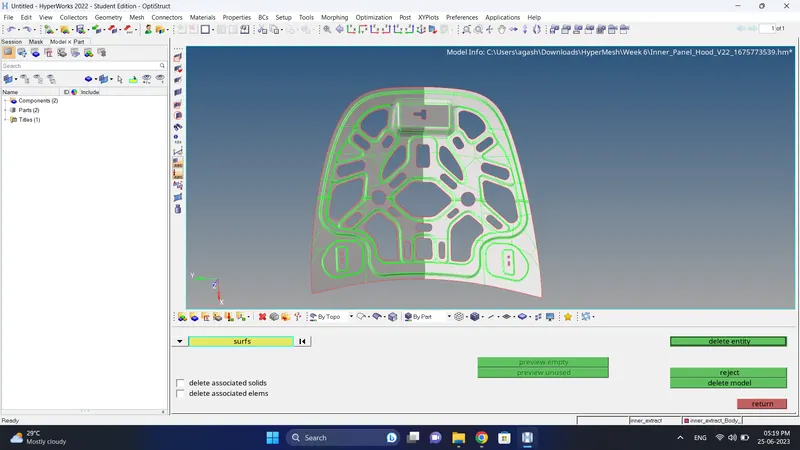
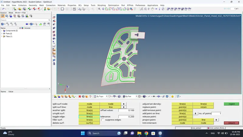
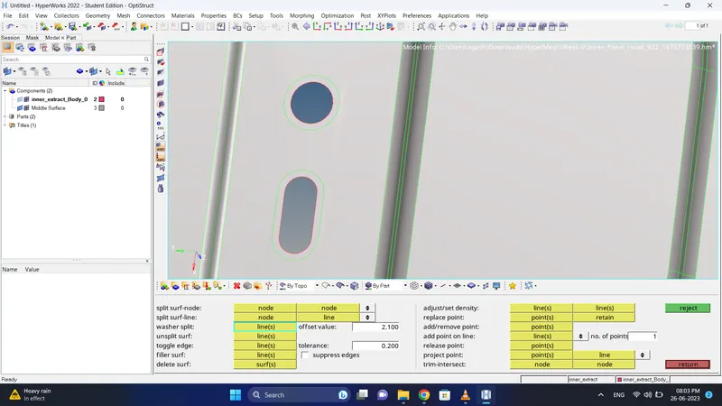
6. For near hole area create washer to get better mesh flow near edge.
Note: while creating washer split give offset value +0.1 min length
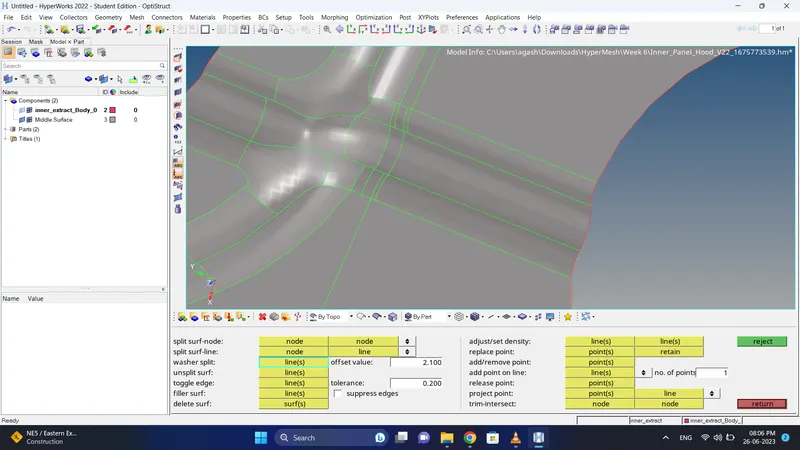
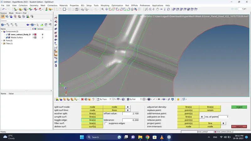
7. If for some area surface edges are not proper, suppress those and create a new using Geometry-Quick edit- Toggle edge and Split surf line.
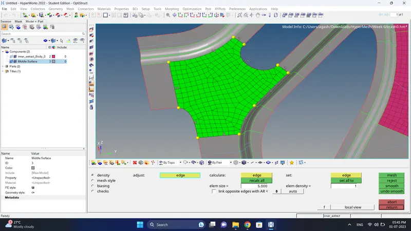
8. Mesh the component and adjusting the mesh flow.
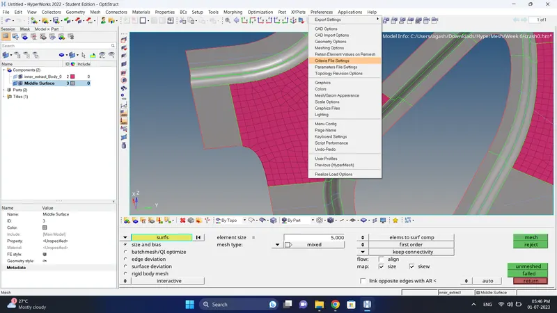
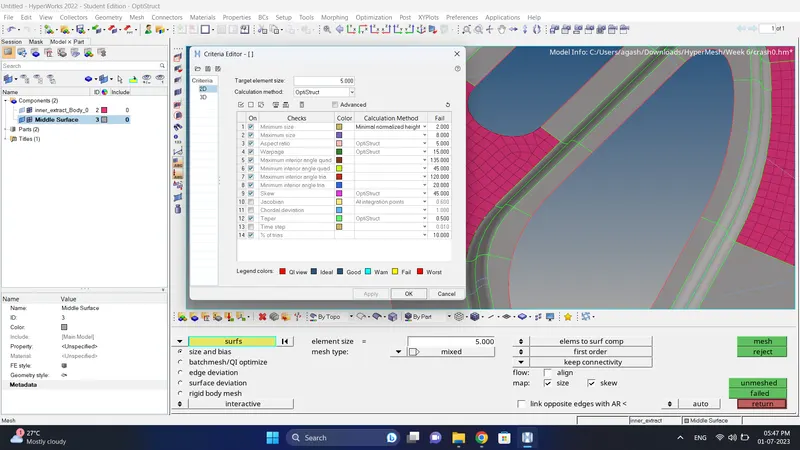
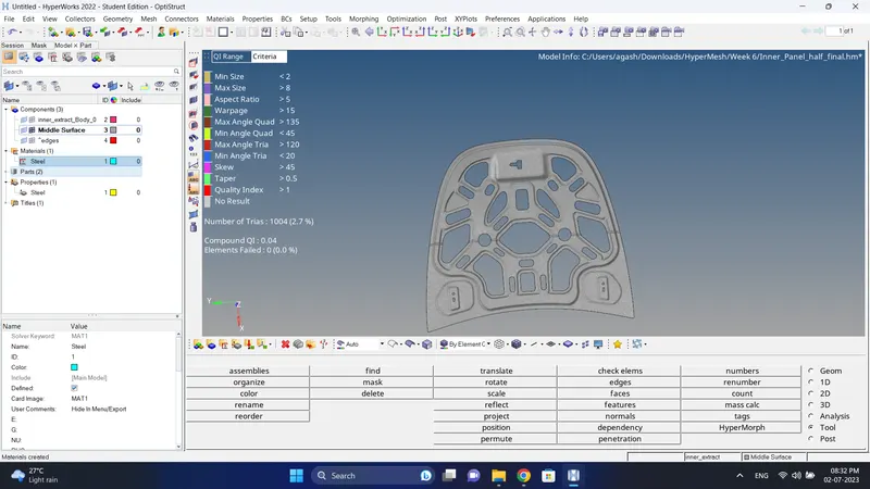
9. While meshing input the quality criteria given by going to Preferences-Criteria file setting.
10. Change the element colour mode to by element quality and check for element failure.
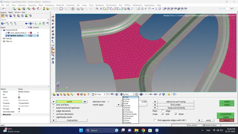
11. Fix the quality using 2D-Rebuild Mesh, Automesh, Replace node, or by using option in quality index.
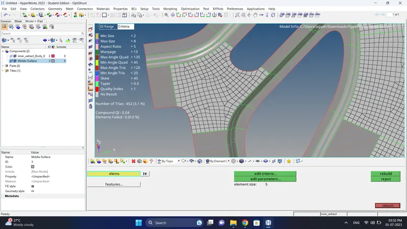
12. Do the same for other areas also.
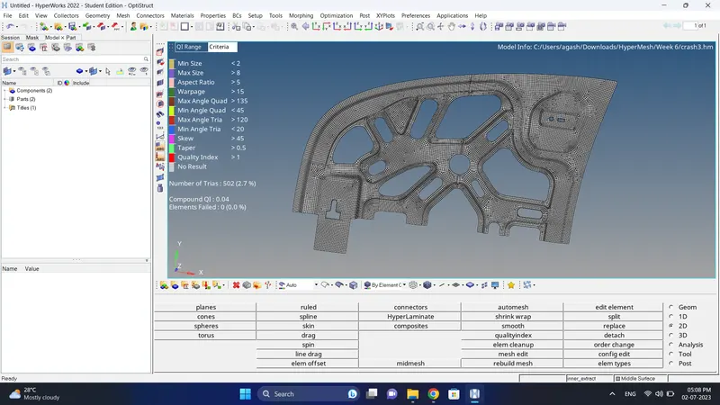
13. Go to the Tool-Reflect, select the element that need to reflect and reflect it.
Note: while reflecting use duplicate option and the reflect it.
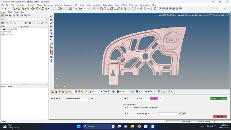
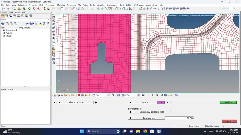
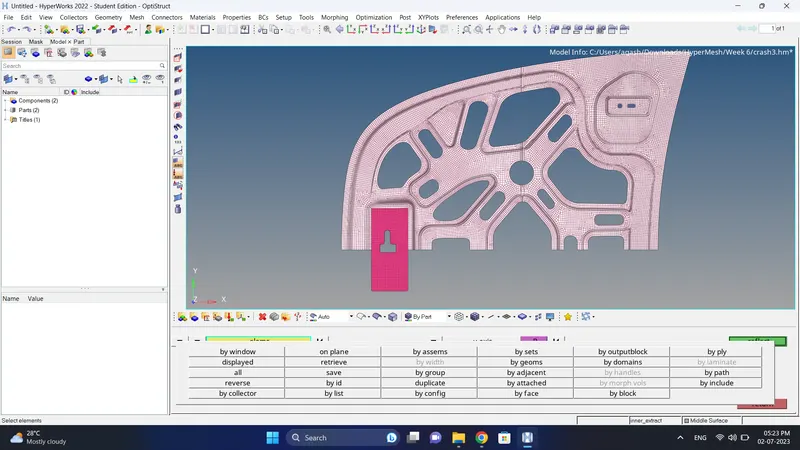
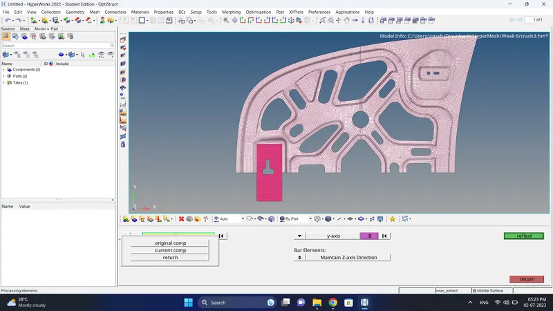
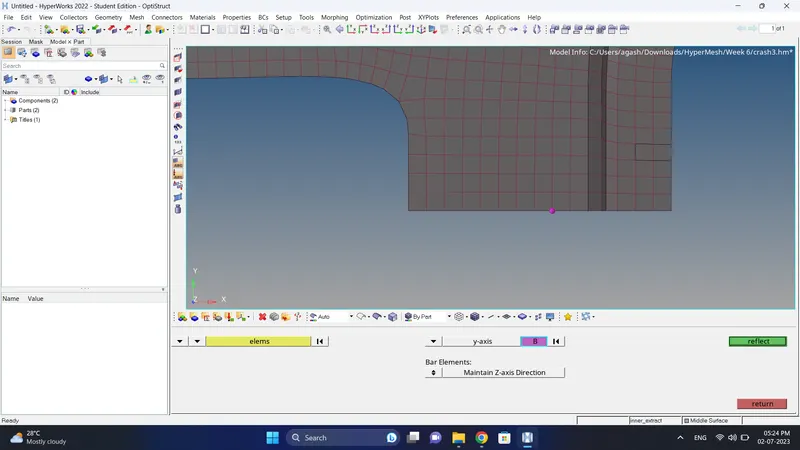
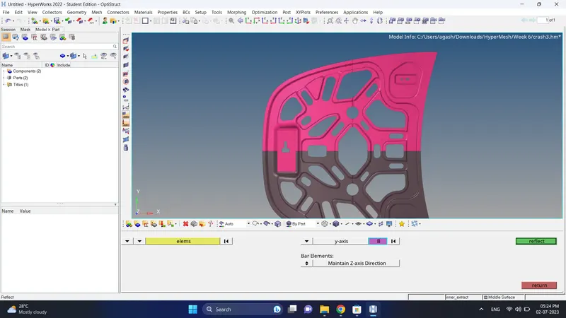
14. After reflecting it go to Tool-Edges, check for edges. If the edges are present in middle the use Preview equivalence and then click on Equivalence.
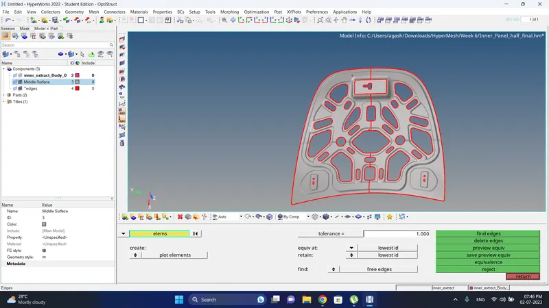
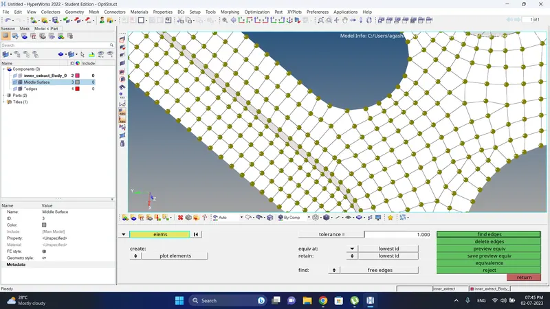
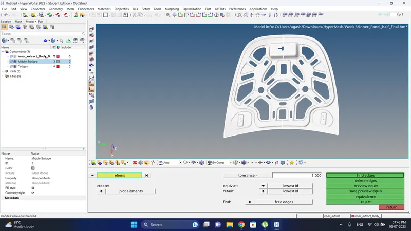
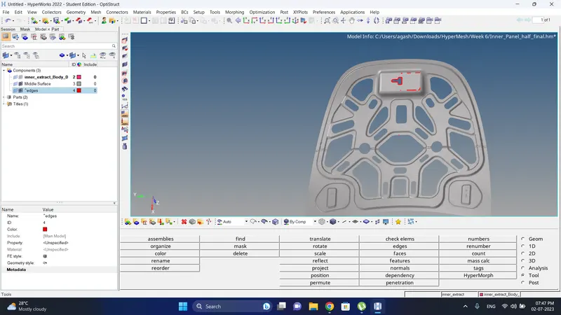
15. After equivalence if there are edges present use paste node option and paste the nodes.
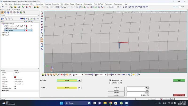
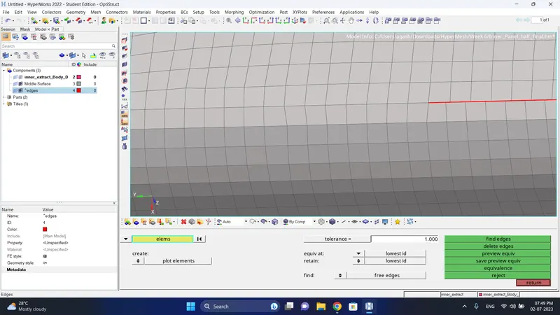
16. After check the free edges.
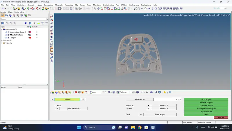
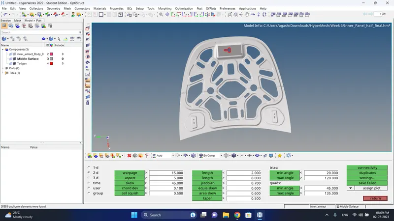
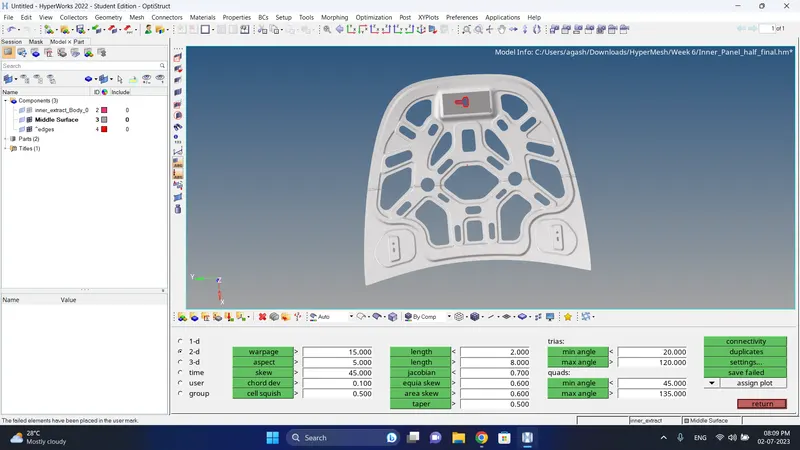
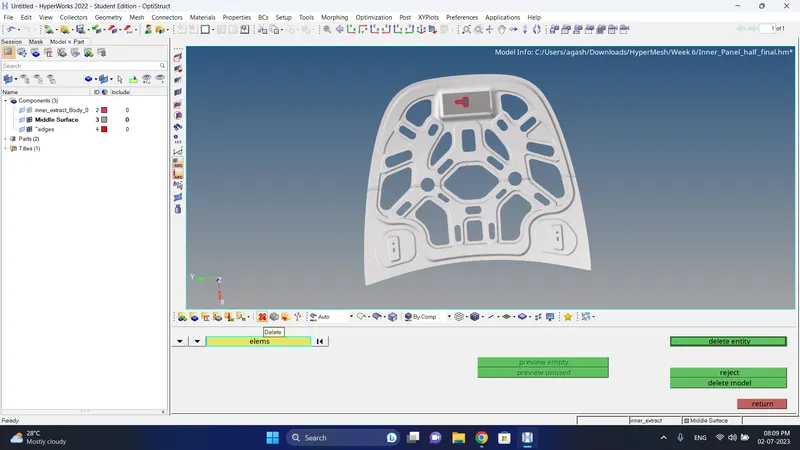
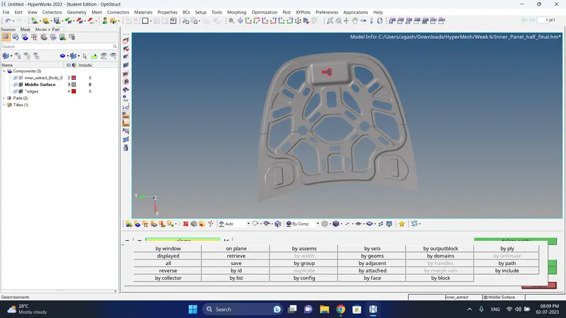
17. Go to the Tool-Check element, click on duplicates. If duplicate element are present click on Save failed. Go to Delete-Element, Click on retrive and delete the duplicate elements.
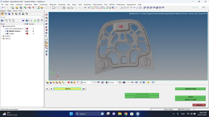
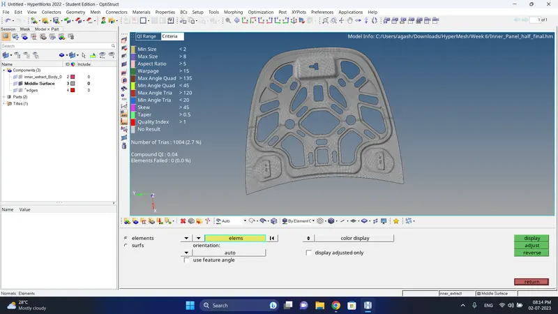
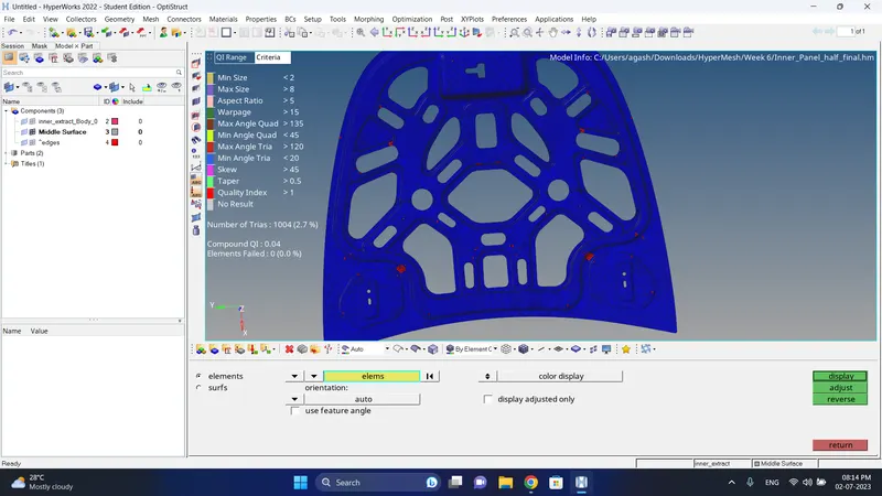
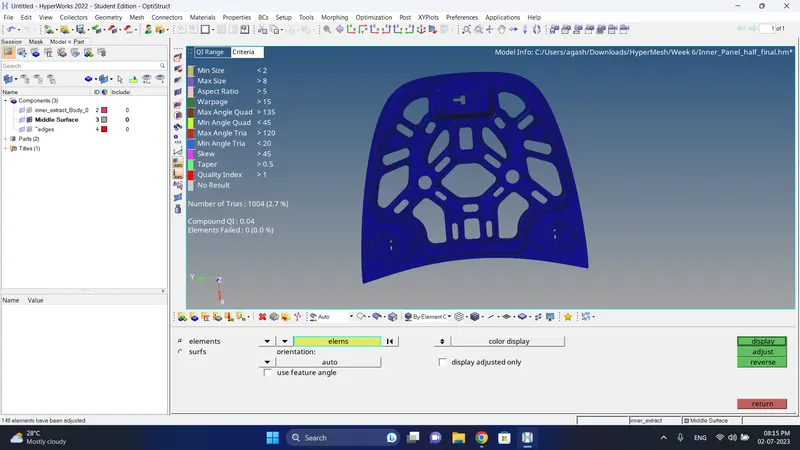
18. Check for Normals, Go to Tool-Normals, select element, click on display and check.
If there are change in colour click on Adjust.
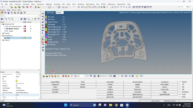
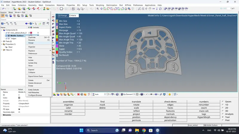
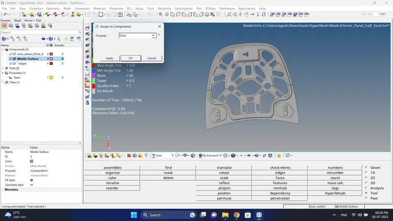
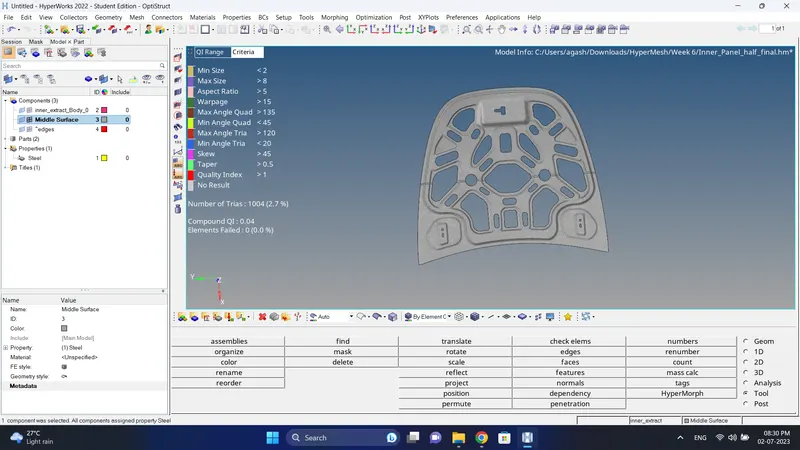
19. Create a Property, measure and give thickness value, Assigh the Property to Mid-Surface.
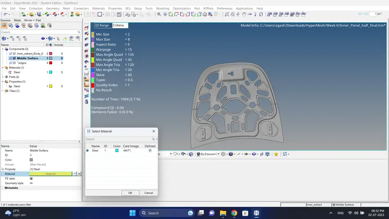
20. Create a Material card and assign the masterial to Mid-Surface.
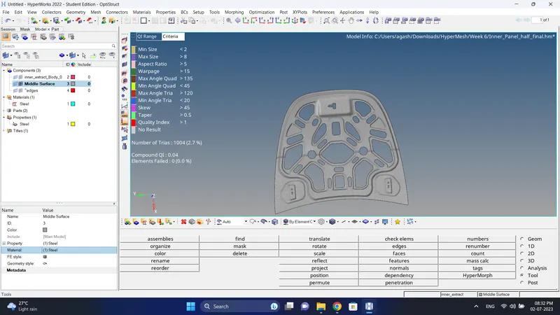
21. Do the final Check and Model is complete.
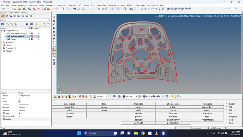
Final Model Image:
Result:
Meshing of the given component is done successfully as per given quality criteria and target length.