Week 6-Meshing of Hood Challenge
Objective : Mesh the component given in the question and assign thickness to it.
Geometry :
Midsurface Extraction :-
1 ) Initially check the CAD model and if the CAD surface is proper then extract mid surface out of it.
2 ) For extracting the mid surface
i ) Go to 'geom' page;
ii ) Then ' midsurface ';
iii ) Extract mid surface.
3 ) While extracting the mid surface, often the surface gets distorted.
4 ) So, before moving to meshing check for the geometry. i.e., any deleted face or distorted face.
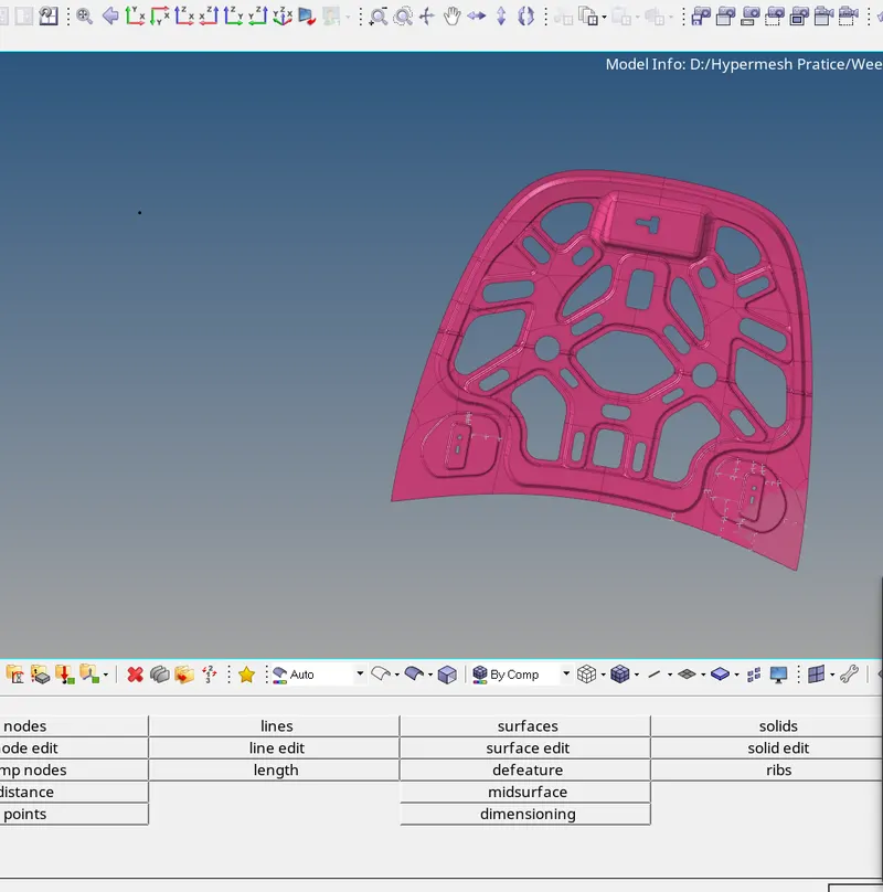
Fig.1 CAD model
5 ) If the surface is distorted in any manner then correct the surface before meshing.
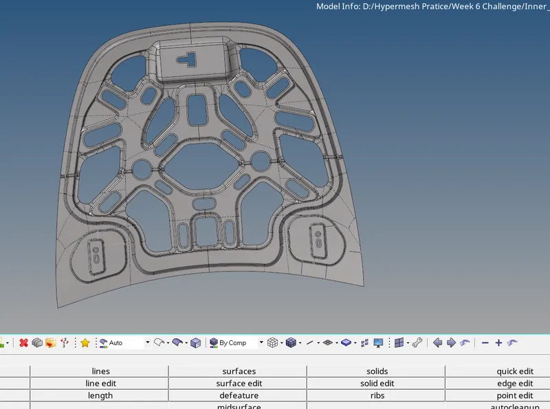
FIG. 2 MID SURFACE
MESHING :
1 ) Meshing is the process of dividing the surface into smaller elements.
2 ) A mesh is a net like structure which houses small elements.
3 ) Elements are made up of nodes and lines. They can be of any shape, such as quad, tria, tetra or any spacial shape depending upon our requirement.
4 ) While meshing take care of few things -
i ) Tria elements - There should not be tria elements present near edges, curves, holes or on any feature line.
ii ) Rotating quads - Rotating quads should be avoided as it would affect the simulation results.
5 ) For meshing the surface go to " 2d " panel.
6 ) Then select " automesh " and select ' surfaces '.
7 ) If mesh flow is not proper then remesh the mesh again and adjust no. of elements on the edges of remeshing selection box.
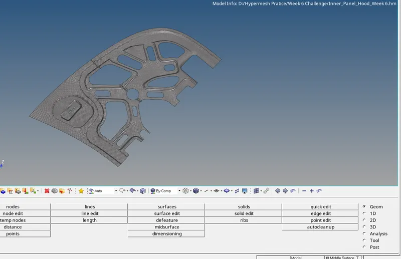
FIG. 3 Partially meshed hood panel.
8 ) Here, the given model was symmetrical. Hence, mesh half of the surface about symmetry and then reflect on the other part.
9 ) To reflect the mesh, go to " tools " panel then select ' reflect ' option.
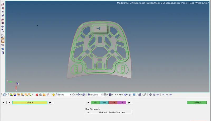
FIG. 4 MESH REFLECTED TO OTHER HALF OF HOOD PANEL
10 ) Once meshing is done, try to improve mesh flow. It should be in proper pattern.
11 ) And the tria concentration should be less. Means, tria in perticular area should not be more or tria elements should not be close to each other. Try to avoid them.
Quality Parameters :
1 ) We have to check our mesh with given quality criteria. This criteria is related to elements of mesh.
2 ) Our mesh must pass the criteria given for all parameters. A threshold value is given in the question which is the boundary condition for failing the element.
3 ) Clear all the failing elements in the mesh as they will alter the results after solving.
4 ) There are many ways by which we can give the values of quality criteria. One of the way is go to -
i ) Preferences from top toolbar.
ii ) Criteria file selection
5 ) Fill all the values and click on apply button.
6 ) We can check quality parameters from " 2D " panel -- > ' qualityindex ' subpanel.

FIG. 5 '2D' PANEL
MODEL CHECK :
1 ) At last do the model check.
2 ) They include -
i ) Find Free edges
--> Tools
--> Edges
--> Click on find edges.
ii ) Element to surface check
--> Mesh
--> Check
--> Elements
--> Comparison
--> Select source elements
--> Select target entities
--> Click on run.
iii ) Check normals
--> Tools
--> Normals
iv ) Dependency Check
--> Tools
--> Dependency
v ) Penetration Check
--> Tools
--> Penetration
Assigning Thickness to model :-
1 ) Create material section;
2 ) Then select the property section assign thickness of model there.
3 ) Now, assign this property to our mid component.
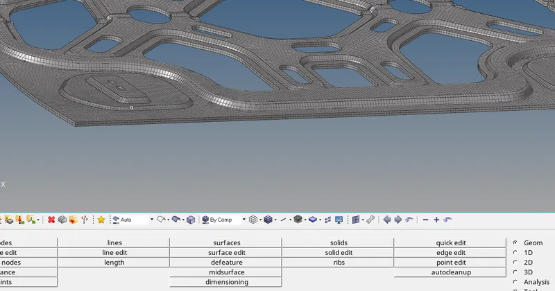
FIG.6 MODEL AFTER THICKNESS ASSIGNMENT
RESULTS :
At the end of this model we achieved a completely meshed model with given element size and type of element.