Week 6-Meshing of Hood Challenge
AIM: Mesh the given part with the given mesh parameters.
For meshing the given model, the steps are as follows:
Step 1: Import the given model using File - Import - Geometry - (Select IGES file format).
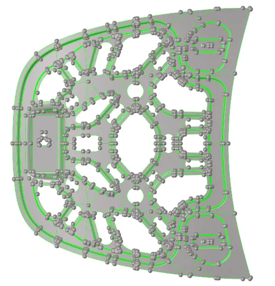
Fig: Imported Geometry
Step 2: Check for the thickness of the component to determine if the model is Plast or Sheet metal.
Since the component had uniform thickness, it falls under sheet metal criteria.
Step 3: Check for the Solid or Shell element (selection)model and remove the Solid part if the thickness is less than 6mm.
Shift +F2 - Select "Solids" - by display - delete
Step 4: Geometry Cleanup (Wireframe geometry View)
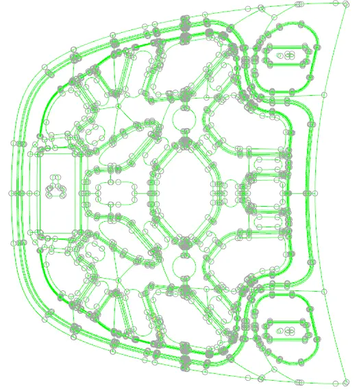
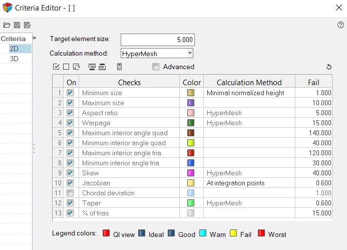
Step 5: Set Quality Criteria as given in the problem
Preference - Criteria File Setting
Step 6: Midsurface Creation
Geometry - Midsurface - Extraction Option - Skin Offset and auto extraction - surface - display - extract.
Step 7: Preference Settings
Preferences - Criteria File Settings
Step 8: 2D Automesh
2D - Automesh - (Element Size = 5) - Flow: align, Map: Size; Skew - options to be activated.
Step 9: Quality Index
Quality Index - Cleanup Tool - Smooth
Step 10: Save failed elements and use mask option to retrieve the element to determine the location of failed elements.
Step 11: Use temp nodes option to locate the region of failed elements and correct the geometry using - Line toggle and draw midline at location lower than 2mm.
Step 12: Once the geometry is ready, use 2D - automesh and smooth option in the quality index to reduce the number of failed elements. Further use rebuild mesh, replace, smooth and translate options to further reduce the number of failed elements.
Conclusion:
The final meshed geometry is saved with 0.1% failed elements, which is determined to be within an acceptable range.