Week 6-Meshing of Hood Challenge
Objective: To extract the mid-surface for meshing for the two components below whose thickness is 6mm.
CAD Model: Hood_model.hm
Procedure:
- Importing the Model
- Open the Hyperworks Desktop - 2022 Student Version.
- Then Click on Import Solver deck icon
 present on the top toolbar.
 - Click on Import Model icon
 from the list of options. Click on the File icon and upload the model. The files will be either listed below or click on the File icon below to load the hypermesh model from the desired destination folder of the computer.
 - Finally cllick on Import. The model gets loaded into the workspace.
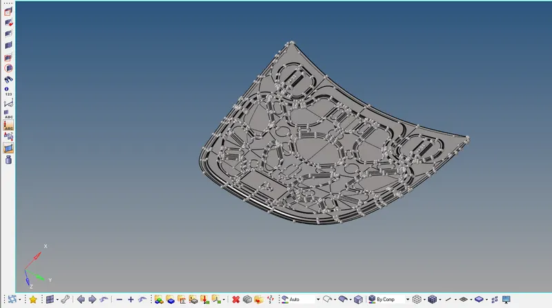
2. Segregating the complete Assembly into individual components
- Change the Geometry color model to "By Topo"
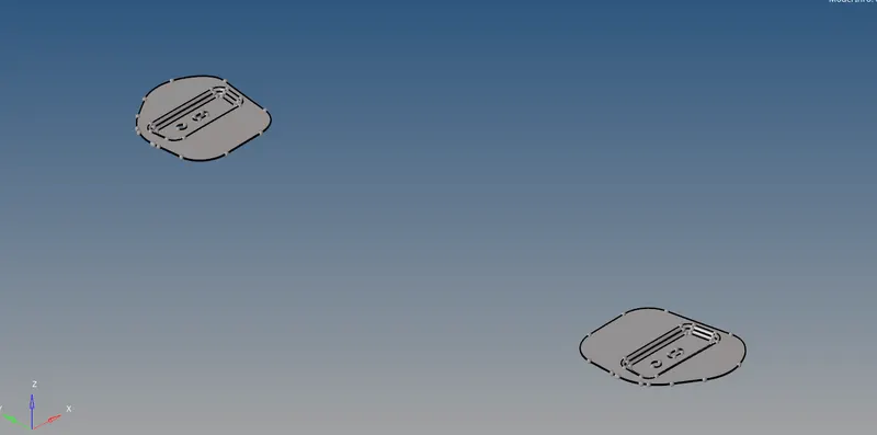
- Segregate each component of the complete assembly by disabling the
 icon for remaining components.
 - First component selected is
 and shown on the workspace.
- The given components are solid components of desired thickness where 2D surface meshing can be performed. To delete the solids from this component click on
 icon present on the bottom tool bar or alternatively press F2 directly from the keyboard.


- Click on the dropdown adjacent to Surfs and from the list click on Solids. Upon clicking on Solids click on Displayed the solids get selected.

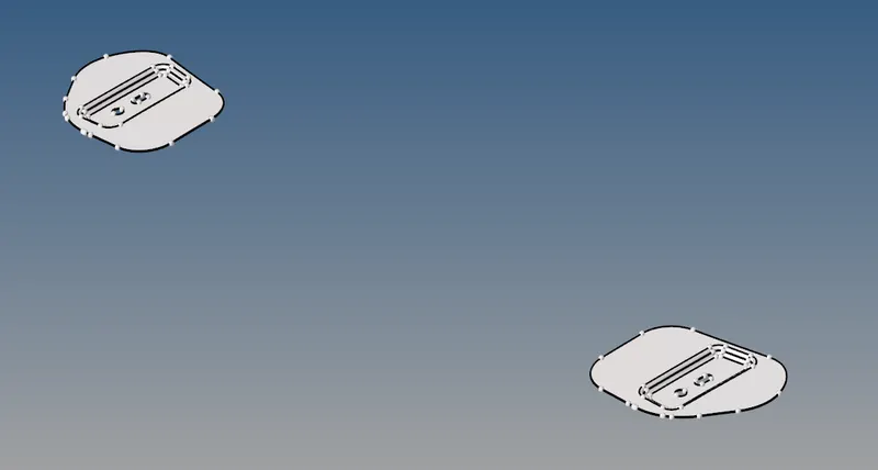
- Click on Delete Entity. The solids of the component gets deleted and surface remains on the workspace.
3. Generating the midsurface of the Hinge reinforcement extract
- To extract the midsurface, click on bulllet next to Geometry and click on midsurface.

- In the Autoextraction option, we click on the arrow next to the surfs and selected displayed to completely select the hinge reinforcement.


- From the extraction options, for our convenience, we select offset+planes+sweeps option from the dropdown. Finally we click on the extract option.
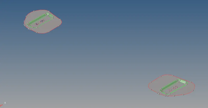
- The extracted midsurface would look like this.
To perform preliminary checks on the imported model, we do a short tweaking of the model.
- Click on bulllet next to Geometry and click on autocleanup
- In the autocleanup option, we click on the surfs and selected displayed to completely select the model.


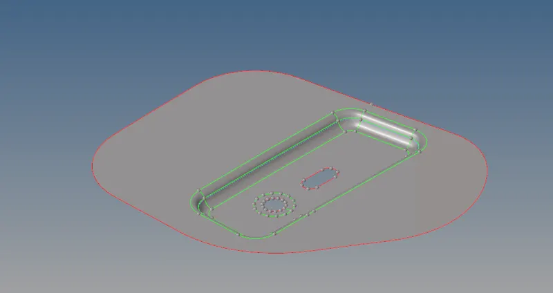
- Finally we click on autocleanup to clean the model. The cleaned up model is as shown below.

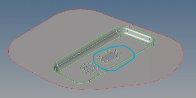
- In addition to autocleanup of the model, we also perfom some manual quality checks like addition of washer-split to provide a proper flow of mesh to circular edges. To avail this option we click on quick edit on Geometry.


- We provide the offset value as 5 and select the lines from the component. The Washer split gets created.
4. Generating the mesh on the midsurface of the Latch reinforcement extract
- From the bottom toolbar click on bullet next to 2D and further click on Automesh option. Alternatively one can press F12 from the keyboard. This opens the automesh option directly.

,
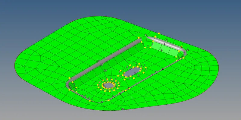
- From the surfs option click on Displayed. This will select the hinge reinforcement surface on the workspace. Input the element size as 5mm and mesh type as mixed.

- Click on Mesh. The component gets meshed as shown below:
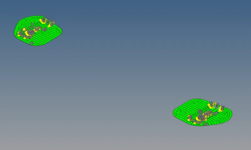
- We adjust the mesh by increasing/decreasing the numbers given on the mesh and bring in fine quality of mesh by having a proper mesh flow.
5. Following the below-mentioned quality criteria while meshing.
- To set the desired quality criteria for the meshed assembly, we replace the default values and input the new values given on the table below.
Target Element Length = 5 Units
| Sl no. | Quality criteria | Value |
| 1 | Aspect ratio | 5 |
| 2 | Skewness | 45 |
| 3 | Warping | 15 |
| 4 | Taper | 0.5 |
| 5 | Minimum Length | 2 |
| 6 | Maximum Length | 8 |
| 7 | Minimum Angle quad | 45 |
| 8 | Maximum Angle qud | 135 |
| 9 | Minimum Angle Tria | 20 |
| 10 | Maximum Angle Tria | 120 |
- To check on elements criteria, we click on Tools and look out for check elems on the fourth column. Alternatively, one can press F10 directly from the keyboard.

- Adjust the values of the required parameters given in the table above and click on the parameters repeatedly to check for errors in elements

6. Rectifying errors generated in the element while meshing.
- The errors are rectified on the element by a number of methods :

- Rebuilding the mesh : By Shift + left click to select the required region of the mesh and clicking on rebuild.

- Element Cleanup: The elements having errors are displayed on the workspace. Select those elements and click on cleanup.

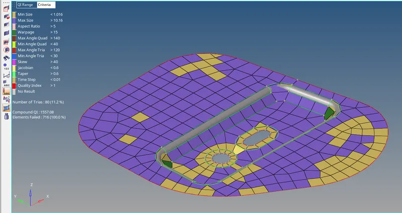
(An example on how error elements failing to meet criteria are shown on the workspace. One needs to clean them up by performing suitable operations)
- quality index: One can click on cleanup tools and use various options to tweak the elements of the mesh and rectify the errors generated.


- smooth : To smooth the mesh and bringing in uniform spacing between elements.

The above methods are only indicative on how correction of individual elements of the mesh can be done. However based on learner's experience and good grasp of the software, there are numerous methods other than the mentioned above to rectify errors generated on the element.
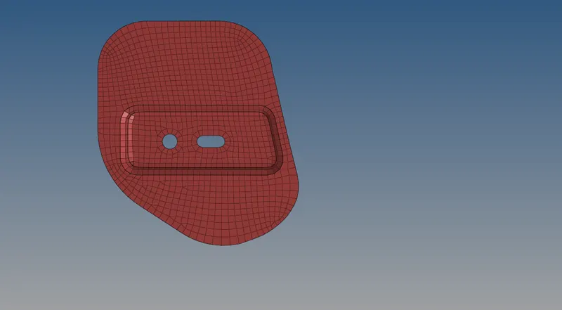
The final mesh generated after removing all the errors are as shown below:
-----------------------------------------------------------------------------------------------------------------------------
Next, we follow the similar procedure to generate the mesh of Latch reinforcement extract, Outer extract and inner extract. The attached hypermesh file is uploaded for reference.