Week 6-Meshing of Hood Challenge
AIM - To mesh the Hood and it's other components.
OBJECTIVE:
- To extract midsurface of Inner extract body of the hood and do the meshing after proper geometry clean-up.
- To extract midsurface of Outer extract body of the hood and do the meshing after proper geometry clean-up.
- To extract midsurface of Hinge Reinforcement extract body_1 of the hood and do the meshing after proper geometry clean-up.
- To extract midsurface of Hinge Reinforcement extract body_2 of the hood and do the meshing after proper geometry clean-up.
- To extract midsurface of Latch Reinforcement extract body of the hood and do the meshing after proper geometry clean-up.
- In each of the above objective proper mesh flow and Quality criteria fulfilment has to be achieved.
PROCEDURE:
PROCEDURE FOR INNER EXTRACT BODY OF THE HOOD:
PROCEDURE:
PROCEDURE FOR INNER EXTRACT BODY OF THE HOOD:
- First the midsurface of the Inner extract body of the hood was extracted using the midsurface option in Geom. Extraction option Offset and Auto.
Geom → midsurface →Extra option (Offset) → Auto Extraction.
- After proper geometry clean up like recreating few surfaces proper split was made on the surface to achieve desired mesh flow and to achieve quality criteria as far as possible.
- Criteria File setting was done before meshing filling in all the quality criteria.
- Step by step meshing was done following one proper direction from start to end
- The meshing was done only at 1 half of the symmetry of the inner extract of the hood as it is a symmetrical surface.
- After completing the mesh of one half of the symmetry quality check was done and necessary correction was done to achieve or reach near to quality criteria.
- After completing the mesh and quality criteria correction on the elements on one half of the symmetry the mesh was reflected to other half of the symmetry but before reflecting all the elements were duplicated.
Tool → Reflect → Select the displayed elements → duplicate → Select N1, N2, N3 and B → press reflect.
- After reflecting the elements, checked for free edges. There were free edges and it was removed by first doing equivalence and then which were left, remeshing or recreating the elements at those places was done.
- After clearing the free edges and doing some other model checks like checking normal the process of meshing was completed.
PROCEDURE IMAGES:
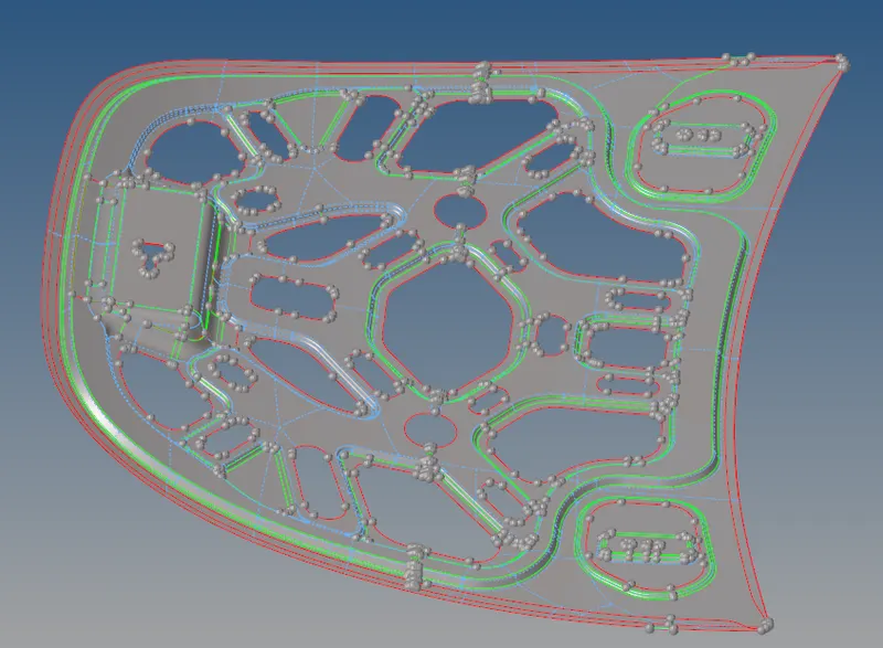
- The image shows the extracted midsurface of the inner extract of the hood
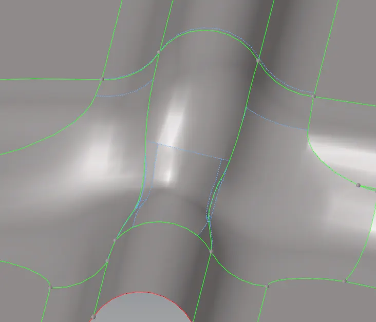
- The above image shows the midsurface cleaning on the feature lines by toggling unnecessary lines.
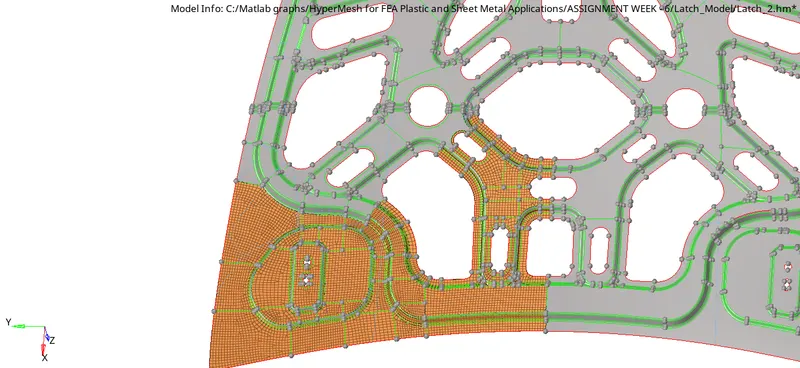
- The above image shows surface slit lines on one half of the geometry along with mesh.
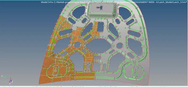
- The above image shows how the meshing was done by proceeding in one direction to maitain the flow of the mesh.
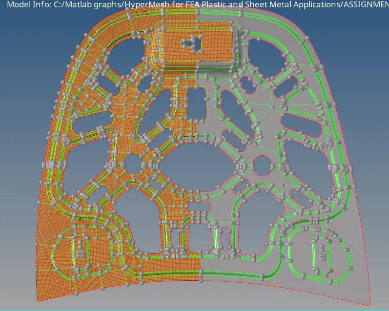
- The above image shows a fully half meshed surface.
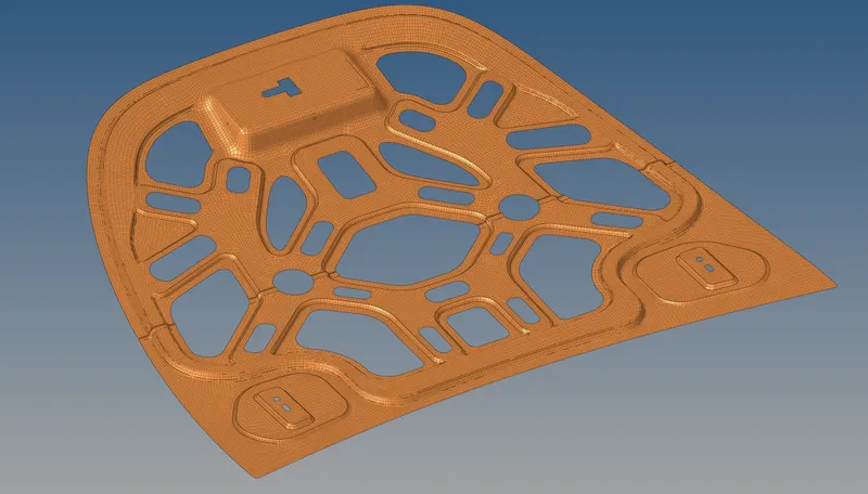
- The above image shows a fully meshed inner extract of the hood.
THE OTHER 4 COMPONENTS:
Same procedure was followed for all the other 4 componets as the above. The reflect command was only used for inner and outer extract of the hood as they are symmetrical body. For the Hinge and the Latch reflect command was not used as they are not symmetrical component. Rest all the procedure were same as above.
PROCEDURE IMAGE - OUTER HOOD:
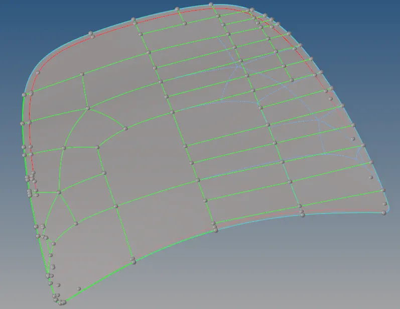
- The above image shows the mid surface of outer extract of the hood along with split line on the right hand side that are made to achieve fine mesh quality and desired quality criteria. All the necessary geometry clean-up was done before splltting the surface specially on the edges.
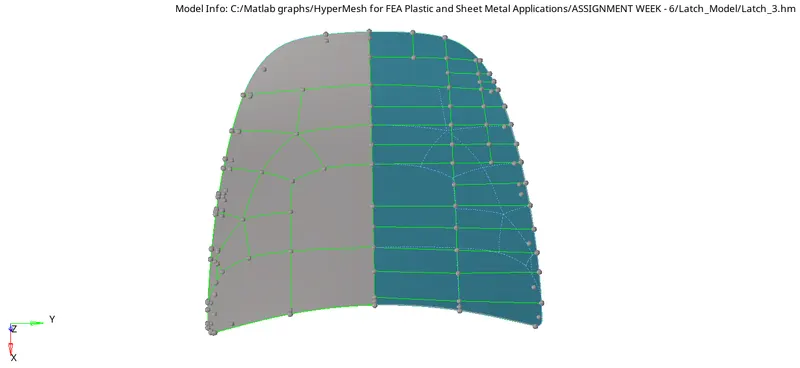
- The above image shows a half meshed outer hood midsurface which has achieved a fine mesh quality and fulfiled all the quality criteria.
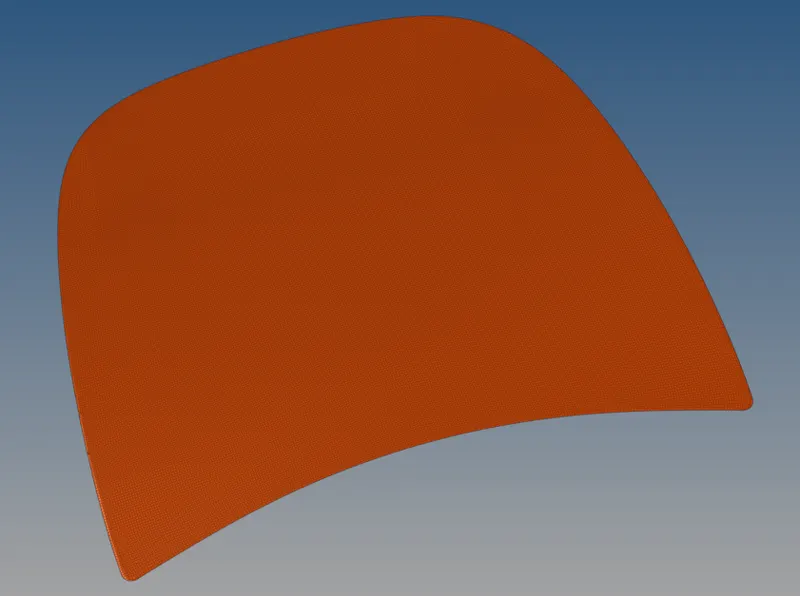
- The above image shows a fully outer hood meshed surface.
PROCEDURE IMAGE - HINGE REINFORCEMENT - 1:
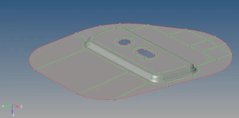
- The above image shows midsurface of Hinge Reinforcement-1 along with surface split lines which were created after necessary midsurface geometry clean-up. Washer splits are created for better surface and edge cpaturing.
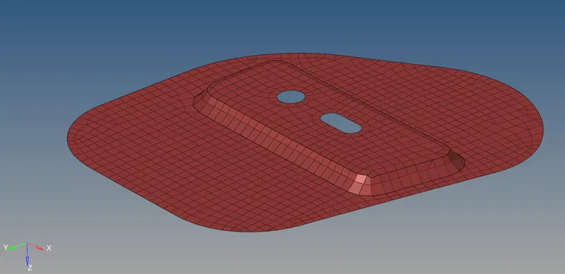
- The above image shows a fully meshed Hinge Reinforcement-1. There are no free edges and it also passes the quality criteria.
PROCEDURE IMAGE - HINGE REINFORCEMENT - 2:
 ]
]
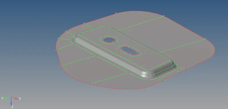
- The above image shows midsurface of Hinge Reinforcement-2 along with surface split lines which were created after necessary midsurface geometry clean-up. Washer splits are created for better surface and edge cpaturing.
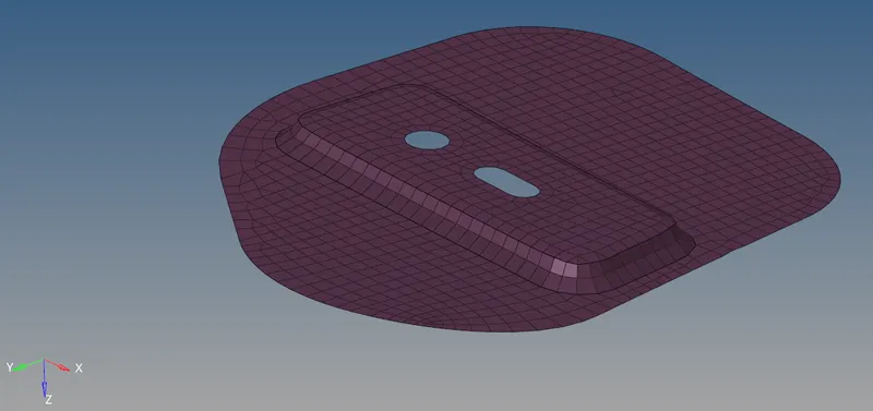
- The above image shows a fully meshed Hinge Reinforcement-1. There are no free edges and it also passes the quality criteria.
PROCEDURE IMAGE - LATCH REINFORCEMENT:
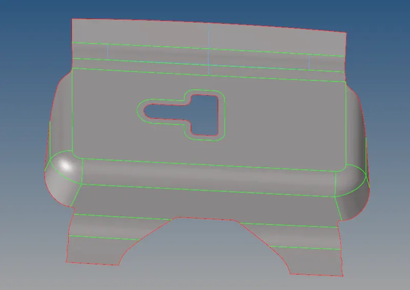
- The above image shows a midsurface of Latch Reinforcement.
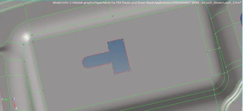
- The above image show defeature surface of Latch Reinforcement.
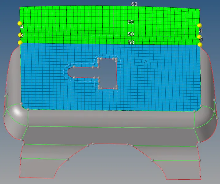
- The above image show how meshing of Latch Reinforcement was started step by step and meshing was done in small portion.
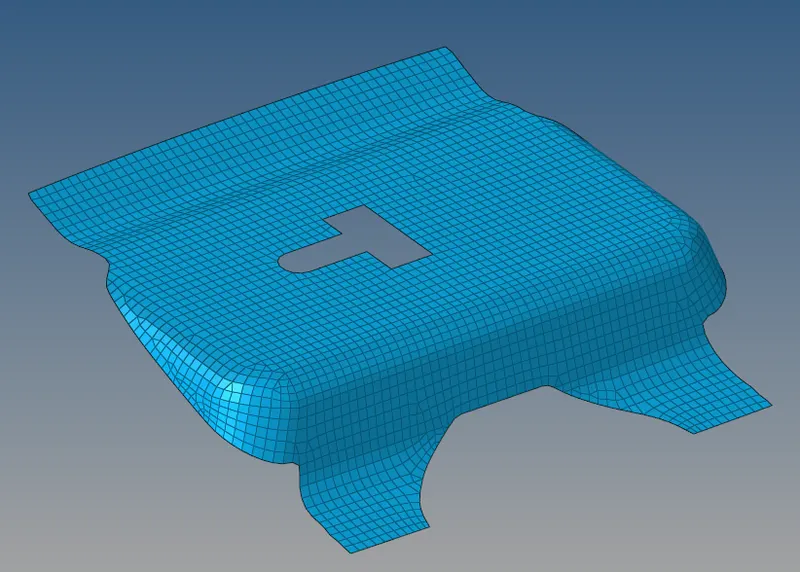
- The above image shows a fully meshed Latch Reinforcement.
OBSERVATION:
- There are very few worse elements which were crtical to be cleared there percentage is very very less.
- Tria percentage was kept below 10% infact far low around 2.2%.
- In manual meshing, step by step meshinhg and proper surface splitting giver great results.
RESULTS:
- All the components were meshed separately and the desired mesh flow was achieved.
- All the Quality criteria was achieved accept for few critical regions.