Week 6-Meshing of Hood Challenge
Advance Meshing using HYPERMESH
Week 6 Challenge
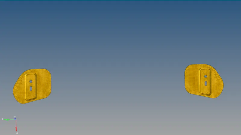
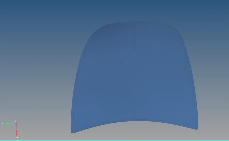
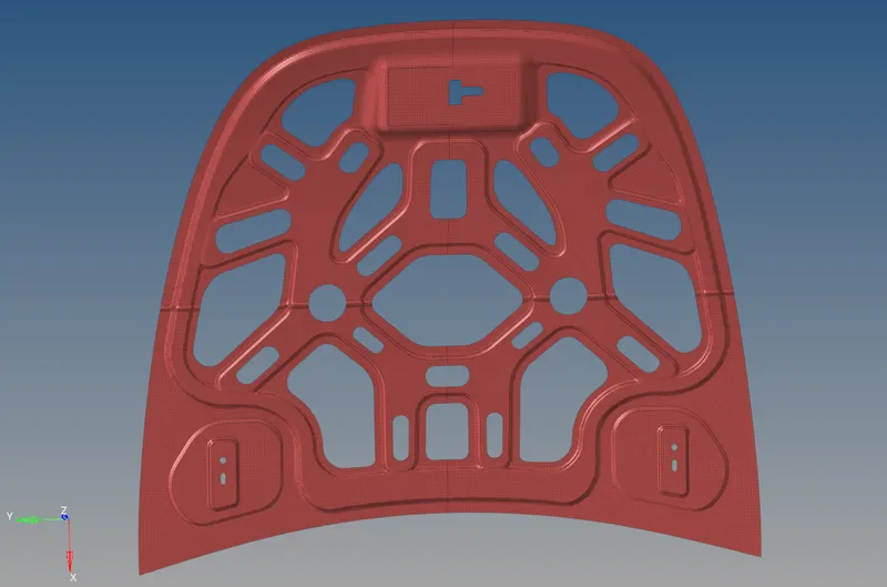
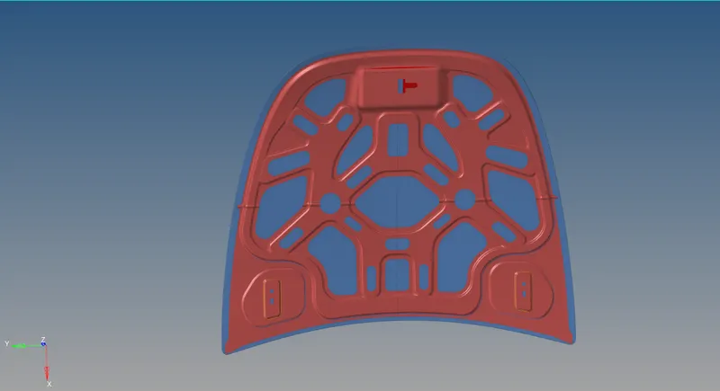
Meshing Engine Hood using Hypermesh
Objective: Clean up the hood geometry and then mesh the geometry with the target element size of 5 mm.
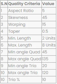
Quality Criteria to be followed:
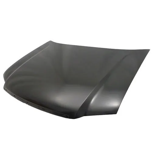
Bonnet is the main component of a car at the front portion. It is used to decorate the car and add a luxurious look. The shape of the bonnet is made aerodynamic to minimise the air effect. Bonnet is generally used to access the parts easily such as radiator, engine, turbocharger and many other parts. In the automotive world, weight optimization plays an important role. In this paper, material changes are applied to the bonnet for the same design and finally show the stiffest bonnet and less-weight component. For designing the hood 3D model CATIA V5 R19 is used, then import the cad model into Hypermesh and pre-processing is done using Hypermesh solver is Optistruct FEA which helps to analyze the hood.
Introduction:
In recent years, work has been done on the bumper and hood design of the vehicle's front end to reduce the injuries to pedestrians in the event of a pedestrian-vehicle collision. The front portion of the vehicle gets damaged including the bonnet when met with an accident. So there is a need to change the existing design of the bonnet or by changing the material. The bonnet is the hinged cover over the engine of motor vehicles that allows access to the engine compartment for maintenance and repair. Bonnet usually does not directly open onto the passenger cell which greatly reduces the importance (weighting) of certain of the functional requirements normally associated with closures such as air-tightness, passenger safety, low cycle fatigue strength etc. The objective of these measures is to reduce the number of road accident fatalities and the severity of injuries sustained by pedestrians involved in a collision with a vehicle in urban traffic. Impact frequency and seriousness of injury have been studied for many years, resulting in rating systems and improved design. The bonnet system is an access panel to the engine compartment to enable maintenance of the power train, drive belts, battery, fluid levels and lamp units. It is fundamentally a reinforced skin panel with many safety and quality requirements.
Literature Survey:
Masoumi studied the comparison of steel, aluminium and composite bonnet in terms of pedestrian head impact. In this paper, a new finite element model has been developed which is capable to simulate the head impact phenomenon between head form impactors and composite bonnet. Then the behavior+ of three identical bonnets made of steel, aluminium and composite have been investigated by the developed model. It is shown that the energy absorption of an aluminium bonnet is smaller than steel and composite ones and for keeping the aluminium bonnet at the same level of stiffness, it is necessary to increase the thickness.
Engine Hood:
The hood which is also known as ENCON, Serves as an access panel to the Engine Compartment of an Automobile. It is an assembly made of Outer and Inner Panels to meet various safety and Design Requirements. The following are the design consideration involved in the Design of the Engine Hood.
- Pedestrian Safety
- Vehicle Quality
- Occupant Safety
- Styling
- Manufacturability
Pedestrian Safety:
Pedestrian safety is always a factor involved in the design of the hood. This is achieved by proper selection of material that can readily deform avoiding risk during impact, Providing embosses to inner panels, etc. This is one of the major factors for a vehicle to have better safety ratings.
Vehicle Quality:
This involves how best the hood can be designed to have better quality in terms of Torsional stiffness, dent resistance(Hailstone and stone chippings), Corrosion resistance better weight distribution, and noise attenuation.
Occupant Safety:
The design consideration must include the impact caused due to Frontal Crash Collapse. Such a Scenario is expected that Hood maintains its Integrity with hinges and also retains any loosed components from the Engine Compartment.
Styling:
Better Surface quality (A-class Surface Finishing), Tight radii on hemmed panel edges & low strain between curved regions of the inner and outer panel.
Manufacturability:
The design should be always considered for manufacturability e.g. Embossing on the inner Panel should have sufficient draft angles provided for the Punching tool to flow in and flow out. Any Design should be studied for Manufacturability to produce it.
Types of HOODS:
- Invalid HOOD or Built IN: It is the lightest of all hood types available, but is easily subjected to border defects and body unevenness during manufacturing. This causes a gap to occur between the hood and the car body. This gap can be overcome hood by establishing a step formed between the hood and car body as shown below. This addition of steps causes an increase in stiffness causing
relatively more damage to the pedestrian. It should be noted that the car body and not on the hood. - Wrap-Around Hood:
These hoods tend to wrap around the car body as shown below. It can mask geometrical defects and achieve adequate stiffness. Wrap-around hoods are relatively safer than other types as it provides more soft areas for pedestrians during impact. - With Fenders: It is the heaviest of all types. these hoods have fenders integrated into them. it is accompanied by a complex corner design thereby making it the most expensive among others.
Some of the common European and Japanese schemes of Hood production:
- BORDER DIAGONAL FRAMES: The design includes the construction of frames that follows the perimeter of the panel along with the support perimeter of the panel supports for hinges and striker.
- BRACE FRAME: The frame is constructed across reinforced areas like hinges and strikers. This type of frame construction supports the outer panel of larger thickness.
Modeling:
Material selection:
The material selection is based on the properties and strength of the material.
Material Used:
Material is chosen such as are they good ductile and formable properties. also the material such be able to sustain impact by absorbing energy by deformation.
Steel Sheets :
Steel sheets of thickness 0.6 to 0.7mm are used for making inner and outer panels. In regions of the reinforced thickness of 1.5mm is implemented. Traditional steel sheets exhibiting low carbon content from (0.02% to 0.08% ), very low controlled quantity of phosphorus, sulfur, manganese, and potentially up to 0.3% of titanium improve the deep drawing capacity, elongation at break
above 40.% and limited thinning.
Aluminium Sheets:
The main advantage of aluminium over zinc-coated steel is the lower specific mass to reduce parts' overall weight since the yield strength of aluminium alloys is not so much lower than most steel grades available in use. Traditionally, the performance equivalence between steel sheets and aluminium sheets was rated in terms of the bending stiffness of the plate and therefore was established by
elastic modulus ratio, in favour of steel with a factor of approx 3. Since the plate bending stiffness is related to the third power of gauge, to obtain stiffness is related equivalence, the required increase of aluminium thickness should be the cubic root of 3 or approximately 1.43. Usually in practice, to replace.
TECHNOLOGY:
Steel sheets are stamped in traditional press lines and assembled by spot welding, arc welding, brazing, and possibly laser welding or fastened using a self-piercing rivet or by clinching.
DESIGN METHODOLOGY:
The design process includes the following.
Master section:
It is a 2D representation of a profile showing inner and outer panels. These include details such as how inner and outer panels are packed and held together, and offset distance between outer panels to different layers of the inner panel.
Embossing:
Embossing is raised projections created on the inner panel for a specific purpose. The major reason is being able to transfer the load from the striker region to the hinges in the event of a collision. It is that path of the load is deviated away from the passenger shell to the hinges. Also, the cuts provided over the inner panels allow sufficient deformation of the outer panel without any restriction caused during a pedestrian impact.
Hemming:
Hemming is a metalworking process in which a sheet metal edge is rolled over into itself. This process ensures both inner and outer panels are interlocked together. Corner relief must be provided to avoid local stress generation and tearing of sheet metal.
Apply mastic sealant:
These sealants serve as binding between the inner and outer panels. A single mastic sealant has an 80mm radius of influence. Upon subjecting this sealant to heat, it solidifies to form a strong bond between the inner and outer panels. These sealants avoid the fluttering of panels during high speed. Mastic sealants are used as an alternative to spot welds.
Position of Hinge:
This Step involves the positioning of hinges. The hood and car body are connected using hinges. This allows relative motion between these structures. The location of hinges should be chosen such that energy during impact dissipated away from the passenger shell and to the A-PILLAR of the car body.
Position Latch and Striker:
This is the final step involved. This step includes locating the appropriate position of a locking mechanism between the hood and car body. The location is decided by tracing a circular path with a hinge axis as the centre. The point where the path traced intersects with the car body should be the location of placing the latch and striker mechanism.
Meshing Methodology:
Step 1:
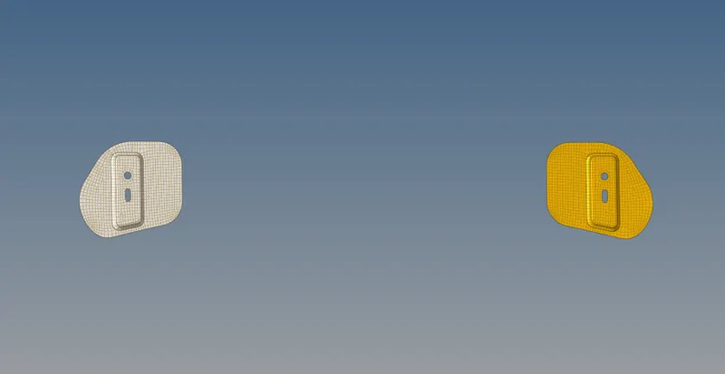
The CAD model is imported into Hypermesh for Pre-processing. 2D shell mesh is used for the meshing of the component. Hypermesh is used to create the mid surface of the component and shell mesh is done for the mid surface. 2D shell mesh is used if the component has less than 5mm thickness.
Step 2:
After importing the geometry, I will extract Mid-Surface for each component and check the symmetry using the symmetry option. So this model due to symmetric I will mesh the model only half and reflect the other side. So my Meshing time can be required for lesser. So, Following Panel is used to extract the mid-surface.

Step 3:
In This Step, I will delete half of the portion of the component, and set the pre-requisite quality criteria.

Step 4:
Using the Auto cleanup option I toggled the lines less than 5mm.

Step 5:
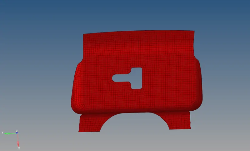
After the cleanup the geometry. I will mesh the model using the auto mesh panel and the set target element length is 5 and the element type is mixed.

Step 6:
Then I will remeshed the area of meshing is not well and avoid the tria element. The quad element gives the best result for Structural simulation.
Step 7:
After meshing half of the portion I will reflect element using reflect option.
Conclusion:
So, In this Challenge, I learned how to clean up the geometry, extract the mid surface, Automesh option, and How reflect the generated mesh.