Week 6-Meshing of Hood Challenge
Week 6 Challenge
Aim
To create the mid surface of the given component and mesh it according to given criteria.
Procedure
- Determine the thickness of the components using the distance command and assign property thickness
- Generate the mid surface of each component individually using auto mid command with different component ids.
- Use the tools organize command to move the mid surface to a different component if they are in the same component.
- Before meshing the component, it is important to defeature areas which will fail for element quality.
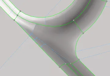
figure 1
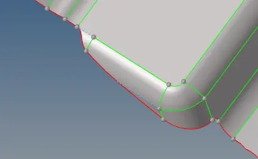
Figure 2
- Removing the fillet for the latch hole will give us a better mesh.
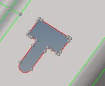
Figure 3
- Unnecessary construction lines and nodes should also be removed for better mesh Quality.
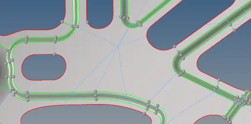
Figure 4
- The construction lines around this feature need to be redone using quick edit options so that the feature capturing is acceptable.
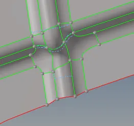
Figure 5
- It is important to note that the lines should not be curved as it will not capture it properly as shown in figure 6
figure 6
- The hemming region in the outer panel needs to be defeatured as it fails for minimum length.
- For this region, we can simply toggle all the edges but the one in the middle for defeaturing as shown in figure 7.
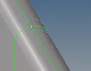
Figure 7
- After we finish the geometry clean up we can go to meshing.
- Note:it is important to finish geometry clean up properly as altering it after meshing will affect the entire mesh and possibly ruin mesh flow leading to a lot of time wasted
- Table 1 shows the required quality criteria for the model.
|
1 |
Aspect Ratio |
5 |
|
2 |
Skewness |
45 |
|
3 |
Warping |
15 |
|
4 |
Taper |
0.5 |
|
5 |
Min. Length |
2 Units |
|
6 |
Max. Length |
8 Units |
|
7 |
Min angle Quad |
45 |
|
8 |
Max angle Quad |
135 |
|
9 |
Min angle Tria |
20 |
|
10 |
Max angle Tria |
120 |
|
10 |
Tria % |
10 |
Table 1
- For meshing, can split the surface to get better mesh flow by introducing construction lines at appropriate locations.
- These options can be found in geoms quick edit split surf-node/line commands.
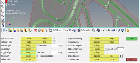
Figure8
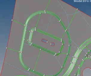
Figure 9
- Using automesh, we mesh the surfaces individually while editing the mesh to fix mesh flow.trias/off elements using rebuild,Quality Index,split and smooth options.
- It is important to keep node count near adjacent surfaces consistent as any difference will lead to node connectivity issues.
- Such issues can be found with tools edges-check edges option, which form 1d elements on areas with connectivity issues so it is easy to find them.
- In certain cases, it may be impossible to view the error in which case we use preview-equivalence and equivalence option.
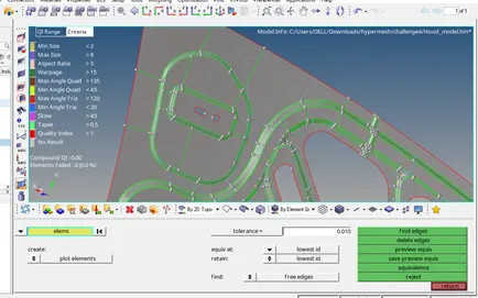
Figure10
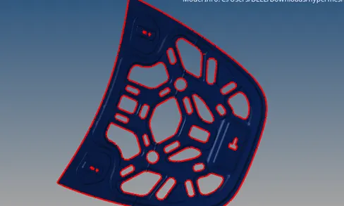
Figure11
- The hinge component can be reflected for the second part to save time using the reflect option along the Y axis.
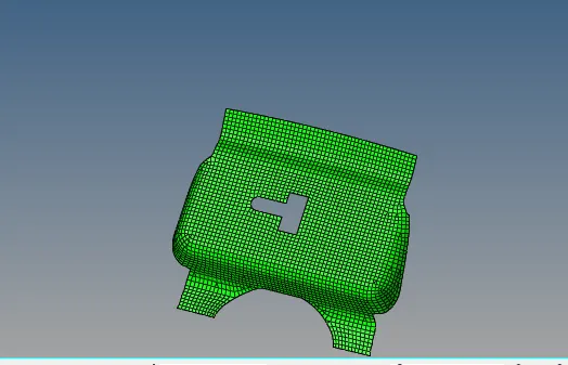
Figure 12
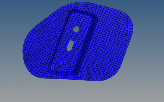
Figure 13
- In the case of Figure 14 while it is possible to solve tria elements by increasing node count, it is not preferred as inconsisted node size will lead to stress concentrations being random at these locations.
- Hence it is preferable to have a few trias instead of solving them for better results.
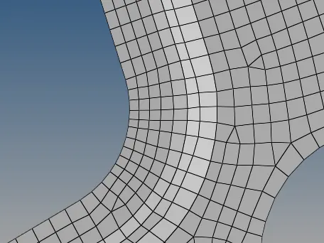
Figure 14
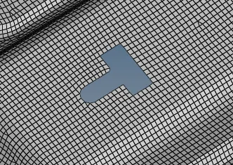
Figure 15
Learning outcomes
- Generating mid surface of components
- Assigning thickness and material properties to components
- Geometry clean uap
- Defeaturing
- Mesh and mesh editing
- Node connectivity
Result
The given hood model was meshed successfully under the given criteria.