Week 6 - Creating connection for Rear door
AIM : For the given FE model of an Automobile, assign PIDs to the different component followed by necessary connection using NASTRAN in ANSA.
INPUT : The input was the FE MODEL of REAR DOOR of an Automobile.
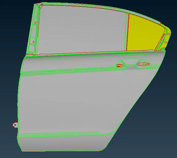
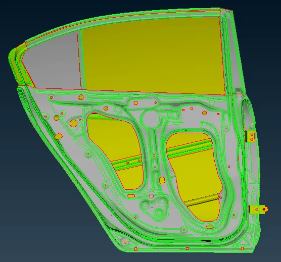
For better analysis of the given model, different PIDs must be assigned to the components and subcomponents. After assigning the PIDs, the model and its components appears as follows.
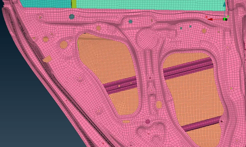
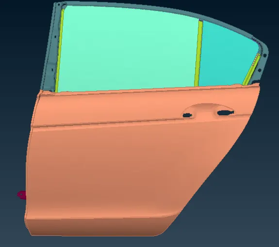
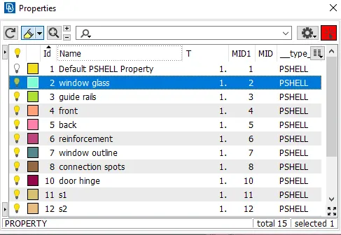
Since all the components of the REAR DOOR is assigned with unique PIDs, we can further proceed to inspect the each connection spot one by one.
CONNECTIONS :
- RIGID BODIES : The rigid bodies are those which are created to rigidly connect with other part with all 6 degree of freedoms arrested given as CM 123456.
- The RIGIDS are made using NASTRAN > ELEMENTS > RBE2 > MANY NODES.
- If the holes containing 6 or more nodes, the correct way is to assign WASHER LIMIT also, such that better stress distribution occurs, otherwise there will be high value of stress concentration. Shown below;
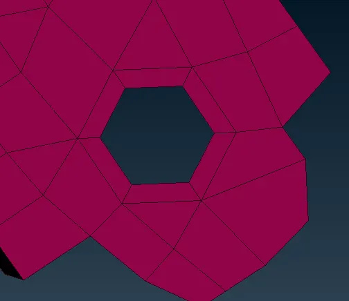
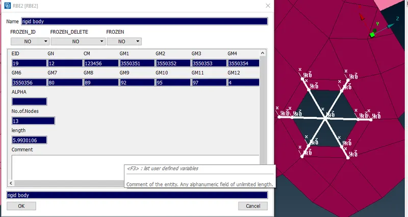
- Above shown is a RBE2 card contains all the information about the RIGID BODY ELEMENT.
- EID : ELement ID.
- GN : Node ID of MASTER NODE.
- GM1,GM2....GMn : Node ID for SLAVE NODES.
- CM : DEGREE of FREEDOM arrested. All 6 DoFs are arrested for RBE.
- RIGID BODY CONNECTIONS ( BOLT CONNECTIONS ) : These are the connections which connects two or more components rigidly using a BOLT and NUT, having defined data.
- As in the below snap, three components are to be joined. steps involved are; first we have to define a COG using POINTS > ON COG.
- As the point is now defined, we go to ASSEMBLY > CONVERT > 3D POINTS > SELECT 3D POINT > SELECT BOLT.
- After defining a bolt connection, now we have to REALIZE the connection using CONNECTION MANAGER in ASSEMBLY.
- Some user defined data is to be fed.
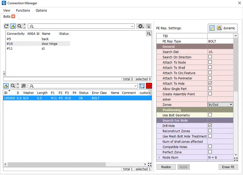
- In above dialogue, in the left table P1,P2 and P3 is to be defined ( max upto P4 ), which are the components to be connected
- In the right table, we have to select the FE REPRESENTATION TYPE ( FE Rep Type) which is BOLT for this case.
- Fed the search distance of 10 and zone type to be IN/OUT, upon applying and realizing, the connection appears as follows;
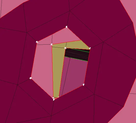
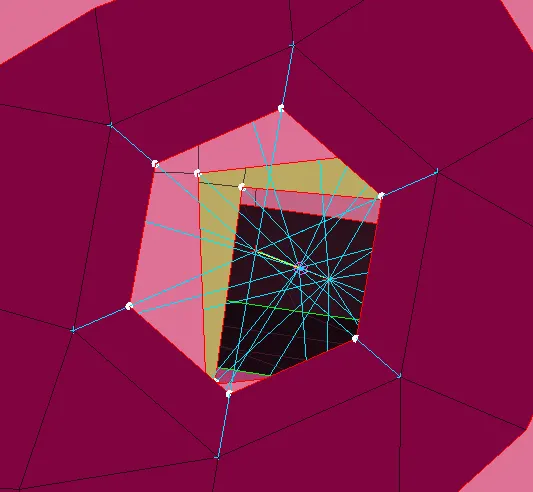
- DOOR HINGE CONNECTIONS : Since the door is meant to form a KINETIC PAIR with the body of the automobile i.e 1 DoF should not be arrested.
- First we need to create RBE2 connection, and as the MASTER NODES are formed we need to create a link between these two using RBE2 > TWO NODES , and the connection will be formed, but the DOF is need to be checked using ELEMENTs > INFO.
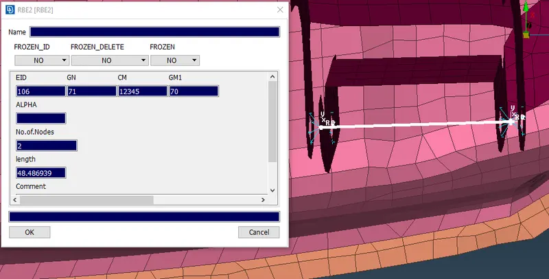
- As shown the CM is 12345, and the left is 6, which will allow the door and body to form a kinectic pair.
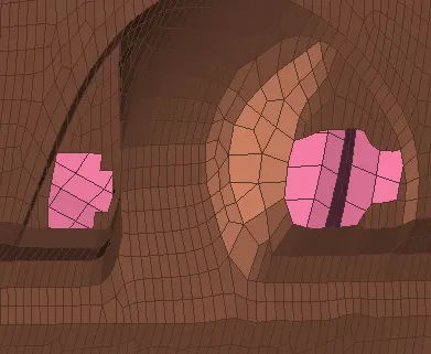
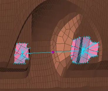
- ASSIGNING MASS TO DOOR HANDLE : As the slots are given to install door handle, we must ensure its probable mass.
- We have to first create rigid bodies in both the slots using RBE2 > MANY NODES and connect two master nodes with a concentrated mass using CONMi>CONM>2NODES.
- The mass assigned will be in tonnes, the mass assigned id 0.0001 tonnes.
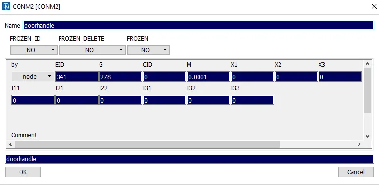
- The result is shown below;
- SPOT AND SEAM WELDING CONNECTIONS : The spot and seam welds are the type of ELECTRIC RESISTANCE WELDING, used to connect SHEET METAL COMPONENTS for both PARALLEL as well as TRANSVERSE connections ( In SEAM WELDING ).
- Steps involved in SPOT WELD CONNECTIONS;
- Define a COG (3d points) using POINTS>ONCOG.
- Convert it using CONVERT in ASSEMBLY , CONVERT > 3D POINTS > SPOT WELD.
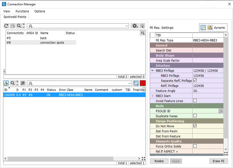
- After defining it, we need to realize it using CONNECTION MANAGER.
- P1 and P2 is to be selected.( components to be joined )
- The FE Rep Type to be selected for spot weld is RBE3-HEXA-RBE3.
- some user define data is to be fed, and all the DoFs must be restricted in RBE3 pinflages in INTERFACE.
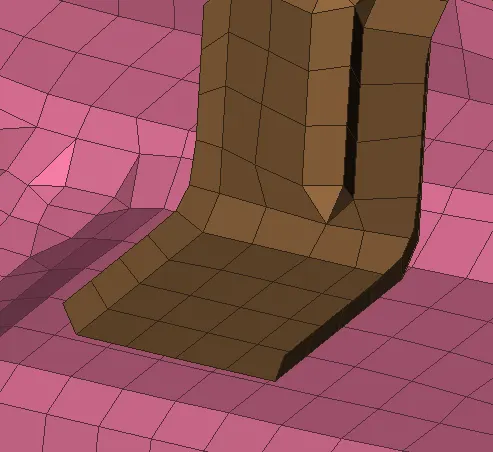
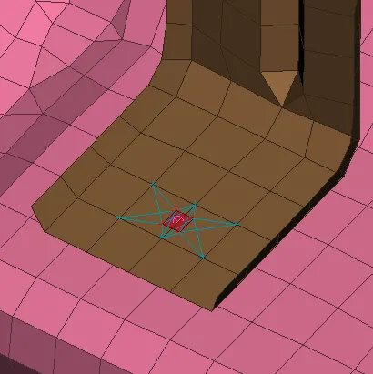
- After APPLYING AND REALIZING the results shown below;
- Steps involved in SEAM WELD CONNECTIONS;
- First we need to extract weld data, since it was not present with the given FE Model, assumptions has been taken and a curve has been drawn accordingly and the converted to SEAM LINE.
- As the SEAM LINE is defined, now we need to realize it using CONNECTION MANAGER.
- Similar to spot welding we need to select parts to be joined as P1 and P2, the base plate should be the thickest among both.
- The FE Rep Type should be taken as OVERLAP SHELL ( FOR PARALLEL CONNECTION ) and YJOINT SHELL ( FOR TRANSVERSE CONNECTION ).
- The ROOT SHELLS is by default taken as DOUBLE ROW.
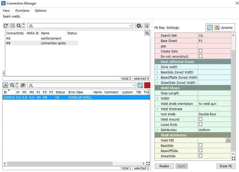
- The final outcome is shown below;
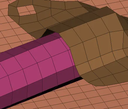
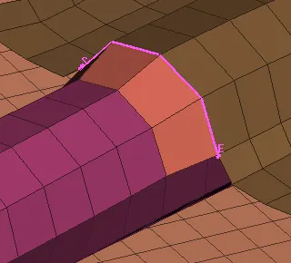
- SEAM WELD PROPERTY IS TO BE CREATED AND ASSIGNED AS WE ARE SHOWING IT AS A SHELL, WE MUST ASSIGN THICKNESS TO IT SO AS TO REFLECT IT IN PRESENTATION PARAMETERS.
- CONNECTIONS FOR WINDOWS : Here the two glass window is to be held by means of a connection which will be completely under friction as the window goes up and down. The window glasses are assigned with WEATHER STRIPS outlined to the frame, which works as a damper ( having defined STIFFNESS) and also isolates the inner atmosphere to outer. The WEATHER STRIPS are provided to both the sides at the bottom and for the rest three edges it will be towards outer.
- As there is no data available for weather strips, we made some assumptions and draw out a curve from it using PERIMETER > FEAT2CURVE.
- As the curve is drawn, we then convert this curve as a SPOT LINE one by one.
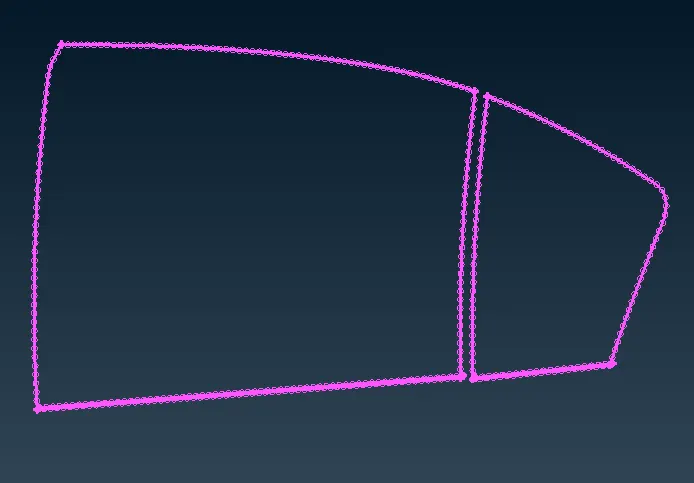
- As we defined SPOT LINES, now we need to realize bush connection by connection manager.
- FE Rep Type for this connection is RBE3-CBUSH-RBE3. Some user defined data is to be fed, here the search distance should be taken more (~50mm), SPACING given is 10mm.
- We must enable KEEPING ALL BRANCHES, PBUSH ID is to be assigned and designated here, as well as the joining parts P1 and P2.
- The PBUSH ID contains the information about all the PBUSH elements.
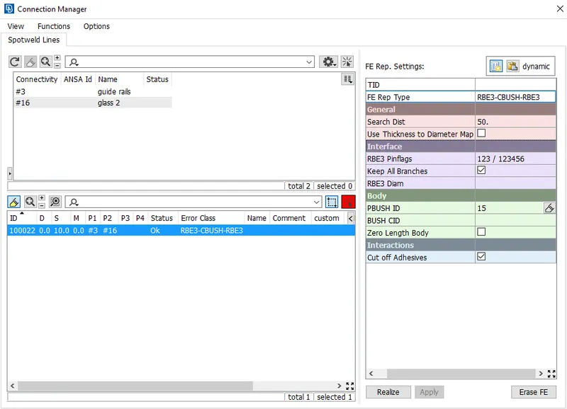
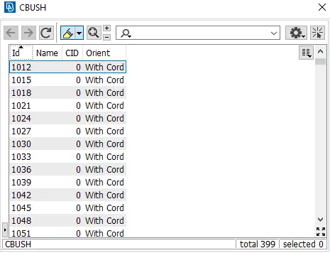
- By APPLYING and REALIZING, we obtain a connection which is aligned with their local axis, we must orient it with global axis.
- It is done by selecting all the bushes in elements in DATABASE and enabling CID to 0 and ORIENT with CORD.
- The final outcome came as follows;
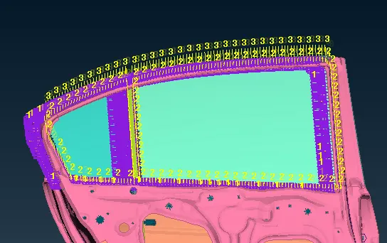
- LEARNING OUTCOMES : Various ways of connecting components and subcomponents has been absorbed and practiced with trial and errors. learnt about assigning degrees of freedom to nodes and connections accordingly, and most important, learnt to install glass window with bushes.
CONCLUSIONS :
- The given FE Model is assigned separatley with different PIDs.
- Rigid bodies are made
- Rigid body connections ( Bolts ) are made.
- Spot and Seam weld connections are performed and described in detail.
- Bushes are installed with window
- All the connections are made proper.